
Call Us
+86 136 6007 9809
Call Us
+86 136 6007 9809

Oct. 24, 2023
A shaft retaining ring can be correctly specified and still fail if it is incorrectly installed, seated in a damaged groove, over-expanded during assembly or used in a retention system that does not match the actual axial load.
For engineers, production teams and maintenance personnel, retaining-ring reliability should therefore be evaluated as a complete system:
Ring → Installation Tool → Shaft Groove → Retained Component → Axial Load → Operating Environment
This is particularly important for external circlips and other groove-mounted shaft retaining rings used to locate bearings, gears, spacers, rollers and other mechanical components.
A useful troubleshooting principle is:
A retaining ring that comes out of its groove is a symptom. The ring itself is not automatically the root cause.
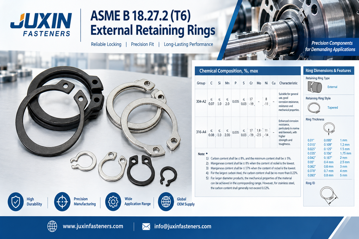
A shaft retaining ring primarily provides axial retention.
In a typical grooved-shaft assembly, the ring prevents a shaft-mounted component from moving beyond a designed axial position.
A simplified load path is:
Retained Component → Retaining Ring → Shaft Groove → Shaft
This means the ring does not work independently.
The performance of the retention system depends on:
correct ring type
correct ring size
ring material and mechanical properties
groove dimensions
shaft material
retained component geometry
installation condition
axial loading
operating environment
A problem with any one of these elements can affect the assembly.
Correct installation begins with product identification.
Before installing an external retaining ring, confirm:
retaining ring standard or drawing
nominal shaft size
groove specification
ring material
surface finish where specified
correct installation tool
part condition
Do not select a retaining ring only because it appears to fit over the shaft.
Similar-looking rings can follow different standards or groove requirements.
Before installation, inspect the component for obvious issues such as:
deformation
corrosion
damaged lugs
damaged installation holes
burrs
cracks or other visible damage
incorrect finish
wrong part or size
For OEM production, inspection criteria should follow the drawing, specification and approved quality plan.
The groove is a functional part of the retaining system.
Before installation, inspect it for:
damage
burrs
contamination
excessive wear
deformation
incorrect machining
damaged groove edges
For a new design or manufactured shaft, groove dimensions should be verified against the applicable standard or controlled drawing.
Do not assume that a ring will compensate for an incorrect groove.
A conventional external circlip is typically expanded using suitable external retaining-ring pliers.
The tool should match the ring geometry and installation features.
Using an unsuitable tool can:
damage the installation holes
twist the ring
cause uneven expansion
scratch or damage the component
permanently deform the ring
Production tooling should also provide sufficient control to avoid excessive deformation during high-volume assembly.
One of the most important installation principles is:
Do not over-expand the retaining ring.
The ring only needs sufficient expansion to pass over the required shaft geometry and reach its groove.
Excessive expansion can produce permanent deformation or alter the spring behavior of the component.
A ring that has been significantly over-expanded may still appear visually acceptable while no longer behaving as intended.
For controlled OEM assembly, installation limits should follow the applicable product or process specification.
Once the ring reaches the correct location, carefully align it with the shaft groove.
Release the installation force in a controlled manner so the ring can engage the groove.
Avoid allowing the ring to snap unpredictably into position.
The objective is not simply to “get the ring onto the shaft.”
The objective is:
Correct Ring + Correct Groove + Complete Seating
A retaining ring may appear installed while being only partially engaged.
After installation, verify that the ring is properly seated around the intended groove.
Depending on the assembly and quality requirements, inspection may include:
visual confirmation
position verification
seating check
component clearance check
automated inspection in high-volume production
The appropriate inspection method depends on the product and risk level.
If part of the ring remains outside the groove, the load path is no longer the one intended by the design.
This can increase the risk of:
ring disengagement
local deformation
damage to the groove
axial movement
unexpected assembly failure
A partially seated ring should not be treated as acceptable merely because the assembly appears stable when stationary.
A groove-mounted retaining ring transfers load into the shaft through the groove.
Important groove characteristics can include:
groove diameter
groove width
groove location
edge geometry
distance from adjacent features
shaft material
The applicable values should come from the relevant international standard, supplier engineering data or customer-controlled drawing.
Do not derive the groove solely by measuring a loose retaining ring.
The ring's free-state geometry is not the same as its designed installed relationship with the groove.
Groove diameter influences how the ring seats and transfers load into the shaft.
An incorrect groove diameter can affect:
engagement
ring stress
seating
axial support
installation behavior
A deeper groove is not automatically stronger, and a shallower groove is not automatically better.
The geometry should follow the validated design.
Groove width affects the relationship between the ring and the retained component.
An incorrect groove width can contribute to:
excessive axial clearance
poor ring seating
unintended ring movement
load concentration
The acceptable clearance depends on the complete assembly design.
Groove edges can also influence assembly performance.
Damage, burrs or deformation may:
interfere with seating
damage the retaining ring during installation
create local stress concentrations
change the intended load transfer
Machining quality and inspection therefore matter.
The retaining ring may be made from a high-strength spring material, but the shaft groove is cut into the shaft.
If the surrounding shaft material cannot support the required load, the groove may deform even when the retaining ring remains intact.
This gives an important failure-analysis principle:
Retaining Ring Strength ≠ Retention System Strength
The ring, groove and shaft material must work together.
When a circlip or retaining ring comes out of its groove, several causes should be investigated.
Possible issues include:
incorrect standard
wrong nominal size
internal ring used where an external ring is required
wrong ring thickness
incorrect replacement part
A ring that can physically be installed is not necessarily the correct ring.
A groove that does not match the intended ring can reduce reliable engagement.
Check:
groove diameter
groove width
groove location
applicable standard or drawing
The ring may have been installed but not fully engaged with the groove.
This can result from:
incorrect tool
poor visibility
contamination
burrs
assembly interference
insufficient inspection
An external retaining ring that has been expanded excessively during installation may become permanently distorted.
Possible symptoms include:
altered free-state geometry
poor groove engagement
uneven seating
reduced retention reliability
Replacing the ring without correcting the installation process may cause the failure to repeat.
Repeated assembly, service loads or previous failures can damage the groove.
Look for:
rounded edges
deformation
wear
impact damage
corrosion
machining defects
Installing a new ring into a damaged groove may not solve the problem.
The actual service load may exceed the assumptions used when the retention system was designed.
Possible sources include:
impact
shock
bearing movement
assembly misalignment
unexpected thrust load
changed operating conditions
Failure analysis should compare actual service conditions with the original design requirements.
If the shaft material or heat-treated condition differs from the approved design, the groove may respond differently under load.
For drawing-controlled OEM components, material substitutions should therefore be reviewed rather than assumed equivalent.
Corrosion can affect both:
retaining ring
shaft groove
Depending on the environment, corrosion can reduce cross-section, damage surfaces or interfere with proper seating.
Material and finish should therefore be selected for the actual service environment.
A removed ring may have experienced:
over-expansion
permanent deformation
wear
corrosion
installation damage
The fact that it can be reinstalled does not establish that it remains suitable for service.
Sometimes the problem is not the ring or installation.
The selected retaining technology may simply be unsuitable for the application.
For example, engineering may need to reconsider:
axial load
groove configuration
installation access
component clearance
shock loading
serviceability
another retaining technology
This should be evaluated at design level rather than repeatedly replacing failed parts.
When a retaining ring fails, a common reaction is:
“Use a thicker ring.”
That can be an incomplete solution.
Changing ring thickness may require changes to:
groove width
groove geometry
adjacent component position
standard designation
assembly tooling
It can also shift the limiting failure mode from the ring to the shaft groove.
Failure correction should therefore start with root-cause analysis.
A useful troubleshooting distinction is identifying what actually failed first.
Possible observations:
permanent ring deformation
fracture
damaged lugs
excessive expansion
corrosion
incorrect ring
Possible observations:
groove-edge deformation
wear
incorrect width
incorrect diameter
material yielding
machining damage
Possible observations:
partial seating
interference
incorrect component stack
unexpected clearance
wrong installation tool
These categories help engineering teams avoid blaming the wrong component.
If a shaft retaining ring repeatedly disengages, use a structured process:
1. Confirm the Part Number
↓
2. Confirm the Applicable Standard / Drawing
↓
3. Measure the Ring
↓
4. Measure the Shaft Groove
↓
5. Inspect Groove Condition
↓
6. Review Installation Method
↓
7. Check for Over-Expansion
↓
8. Verify Complete Seating
↓
9. Review Actual Axial Load
↓
10. Review Shaft Material and Service Environment
Do not skip directly to a stronger replacement ring.
Installation direction depends on the retaining-ring type.
Used on a shaft.
Typically:
Expand → Position → Release into external groove
Used inside a bore.
Typically:
Compress → Position → Release into internal groove
Using the wrong installation technique or tool can damage the component.
E-rings use a different installation architecture.
A conventional external circlip is generally expanded over the shaft.
An E-ring is generally installed radially from the side into an appropriate shaft groove.
Therefore:
External Circlip → Axial access
E-Ring → Radial side access
This difference can influence assembly-line layout and product design.
For low-volume maintenance, retaining-ring pliers may be sufficient.
High-volume OEM assembly may require consideration of:
dedicated fixtures
controlled installation tooling
automated feeding
automated insertion
part presence detection
seating verification
error-proofing
The best retaining component is not only one that meets mechanical requirements—it should also fit the intended manufacturing process.
For high-volume manufacturing, mistake-proofing can reduce assembly risk.
Depending on the production system, possible controls may include:
part orientation control
dedicated tooling
sensor confirmation
vision inspection
presence detection
fixture design preventing wrong-part installation
This is particularly useful when multiple visually similar retaining rings are used on the same production line.
Inspection requirements should be based on risk and drawing requirements.
Potential checks include:
correct part number
correct ring type
correct size
correct finish
no obvious deformation
no corrosion
no installation damage
ring fully seated
correct axial position
no visible interference
retained component positioned correctly
expected clearance maintained
no unintended axial movement beyond design requirements
For critical assemblies, inspection methods should be formally defined.
Visual appearance alone can be misleading.
A ring may look installed while:
only partially seated
sitting against a groove edge
permanently deformed
installed in the wrong groove
installed on the wrong shaft size
A controlled inspection criterion is more reliable than operator judgment alone.
Some retaining rings can have manufacturing features or edge conditions that make orientation relevant to a specific assembly.
Whether orientation matters depends on:
ring design
manufacturing process
load direction
customer specification
Do not create a universal orientation rule for every retaining ring.
Follow the applicable drawing, standard or manufacturer's engineering instructions.
There is no universal answer.
The decision depends on:
ring design
removal method
amount of deformation
service condition
corrosion
customer maintenance requirements
For controlled OEM assemblies, reuse should follow the approved service specification.
If replacement is required by the OEM procedure, the removed ring should not be reinstalled merely because it appears undamaged.
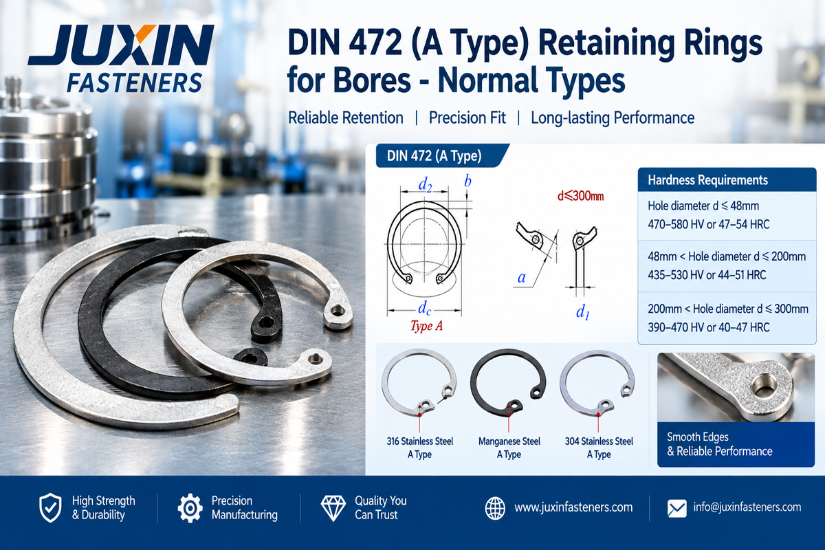
For serviceable equipment, inspection may consider:
corrosion
visible deformation
groove wear
axial movement
damaged installation features
surrounding component condition
Inspection frequency should be based on the equipment's maintenance plan rather than a universal interval.
Automotive retaining-ring assemblies may experience:
vibration
shock
thermal cycling
corrosion exposure
high production volumes
Applications may include suitable:
shaft assemblies
actuator mechanisms
seating mechanisms
transmission-related systems
linkage components
OEM and Tier suppliers may also require:
traceability
controlled materials
process capability
documented inspection
change management
External and internal retaining rings can be used in suitable motor assemblies for axial location of components such as bearings or shaft-mounted elements.
Engineering should evaluate:
axial load
shaft or housing geometry
operating speed of surrounding components
vibration
temperature
assembly process
Retaining rings may locate:
bearings
gears
spacers
shaft components
However, the retaining ring should not automatically be considered the feature responsible for transmitting torque.
Torque transmission and axial retention are separate design functions.
Pump assemblies may use retaining rings in suitable mechanical locations.
Environmental considerations may include:
moisture
fluid exposure
corrosion
temperature
vibration
maintenance access
Material and finish should match the real operating environment.
Heavy equipment can introduce:
shock loading
contamination
outdoor corrosion
vibration
maintenance challenges
A retaining system should therefore be selected and validated for the actual equipment conditions rather than simply copied from a lighter-duty assembly.
For technical evaluation or replacement sourcing, provide as much of the following information as possible:
retaining ring standard
original part number
drawing
ring dimensions
shaft diameter
groove diameter
groove width
ring material
surface finish
photographs of the failed assembly
photographs of the groove
operating environment
estimated axial load if known
failure description
quantity and annual demand
A failed physical sample can also provide useful information when drawings are unavailable.
When reverse-engineering a replacement, measuring only the removed ring may reproduce the wrong solution.
The supplier should ideally evaluate:
Ring + Shaft + Groove + Application
Why?
Because the original failure may have been caused by:
wrong ring
wrong groove
wrong material
installation damage
excessive load
Copying the failed part exactly may copy the problem.
For a standard product, provide:
standard
nominal size
material
finish
quantity
annual demand
packaging requirements
For drawing-controlled components, provide:
2D drawing
dimensions
tolerances
material
mechanical requirements where specified
heat-treatment requirements where specified
finish
inspection requirements
sample quantity
production forecast
For troubleshooting or second-source projects, also provide:
existing sample
groove dimensions
assembly photographs
application information
known failure history
For additional selection and design information, review related resources on:
Shaft Retaining Rings Selection Guide
External vs Internal Circlips
DIN 471 External Retaining Rings for Shafts
DIN 472 Internal Retaining Rings for Bores
DIN 6799 Retaining Washers for Shafts
E-Rings and E-Clips
Stainless Steel Retaining Rings
Spring Steel Retaining Rings
Custom Stamped Retaining Components
These resources help move from general technology selection to specific product specification and sourcing.
JUXIN FASTENERS supplies standard and custom fastening components for industrial OEM and manufacturing applications.
Our retaining-component capabilities include:
external retaining rings
internal retaining rings
shaft circlips
bore circlips
E-rings
E-clips
DIN 471 retaining rings
DIN 472 retaining rings
DIN 6799 retaining washers
stainless steel retaining rings
spring steel retaining rings
custom stamped retaining components
For standard sourcing, send:
Standard → Size → Material → Finish → Quantity → Annual Demand
For drawing-controlled sourcing, send:
Drawing → Dimensions → Tolerances → Material → Finish → Inspection → Quantity
For a recurring failure or replacement project, send:
Existing Ring → Shaft → Groove → Failure Photos → Application → Operating Conditions → Quantity
JUXIN FASTENERS can support drawing review, sample comparison, replacement sourcing and made-to-drawing retaining components for global industrial OEM and supply-chain projects.
Email: info@juxinfasteners.com
Website: www.juxinfasteners.com
 MORE NEWS

Sep. 27, 2026

Sep. 27, 2026

Sep. 27, 2026
Contact Us
Tel.:
+86 020 8621 0320
+86 020 3121 6067
E-mail:
Technical Support:
Navigation
SEND INQUIREY