
Call Us
+86 136 6007 9809
Call Us
+86 136 6007 9809

Sep. 20, 2023
An internal retaining ring looks like a simple spring-steel component.
Its engineering function, however, depends on much more than the ring itself.
A reliable retaining system consists of:
Retained Component → Internal Retaining Ring → Bore Groove → Housing
The ring must fit the groove correctly, the groove must support the required axial force, and the housing material must withstand the resulting contact stresses.
For this reason, selecting an internal circlip only by nominal bore diameter can be insufficient for critical mechanical assemblies.
The more useful engineering question is:
What axial load must be retained, and can the ring, groove and housing transfer that load safely?
For procurement teams, the corresponding question is:
Does “40 mm internal circlip” mean DIN 472 normal type, heavy type, another retaining-ring standard or a drawing-specific part?
JUXIN FASTENERS supports standard and drawing-based internal retaining rings for industrial machinery, automotive and EV equipment,
bearings, gearboxes, pumps, motors, automation equipment, hydraulic systems, HVAC equipment and other OEM mechanical assemblies.
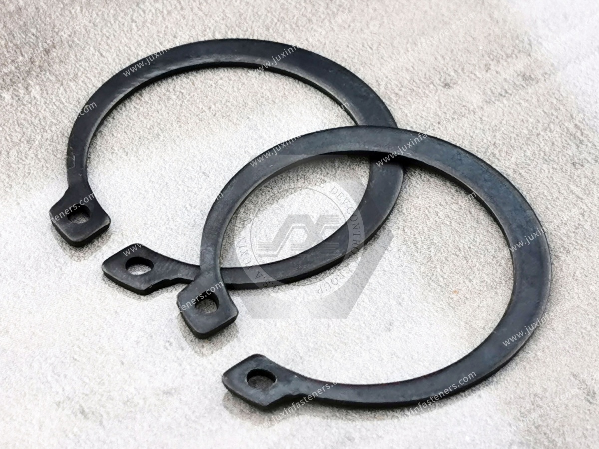
An internal retaining ring is a removable mechanical retaining component installed in a groove machined or formed inside a bore or housing.
It is also commonly called:
internal circlip;
bore circlip;
internal snap ring;
retaining ring for bores.
After installation, part of the ring projects inward from the groove and creates a shoulder that restricts axial movement of the retained component.
A typical assembly is:
Housing → Bore Groove → Internal Retaining Ring → Bearing or Component
The ring provides axial retention without requiring a threaded nut, cover plate or permanent staking operation.
DIN 472 specifies retaining rings for bores and their corresponding grooves.
The standard is intended for retaining components such as rolling bearings inside bores and for transferring axial forces through the retaining-ring system.
The current edition is:
DIN 472:2026-05 — Retaining Rings for Bores — Normal Type and Heavy Type
This edition replaces the previous DIN 472:2017-06 edition.
For new drawings and current procurement programs, engineers should therefore verify the applicable edition rather than automatically copying an older DIN 472 reference from a legacy BOM.
DIN 472 includes both:
Normal Type
and
Heavy Type
retaining rings.
These should not be treated as interchangeable simply because they are associated with the same nominal bore size.
Where a drawing specifies a particular type, procurement should preserve that requirement.
For a new design, selection should consider the required axial retention, groove geometry, available installation space and complete assembly.
One of the most common sourcing mistakes is confusing DIN 472 and DIN 471.
Retaining rings for bores
The ring is installed inside a housing bore.
Retaining rings for shafts
The ring is installed around an external shaft groove.
Therefore:
DIN 472 → Internal / Bore
DIN 471 → External / Shaft
The two product families use different installation movements and groove geometries.
They should not be substituted for one another.
During installation, an internal retaining ring is compressed so that its outside diameter becomes small enough to enter the bore.
Once aligned with the groove, the installation force is released.
The ring expands outward and seats in the groove.
The load path then becomes:
Retained Component → Ring Face → Ring Body → Groove Face → Housing
This load path explains why retaining-ring performance cannot be evaluated from the ring alone.
The primary purpose of a DIN 472 retaining ring is axial retention.
It should not automatically be described as:
a vibration damper;
a radial bearing;
a shock absorber;
a sealing component;
a preload spring.
These are different engineering functions.
A retaining ring can operate in equipment exposed to vibration, but:
Axial Retention ≠ Vibration Damping
If vibration or rotational loosening is the actual design problem, another fastening or retention strategy may also be required.
A common design mistake is to focus entirely on the retaining ring.
In reality:
Correct Ring + Incorrect Groove = Unreliable Retention
The groove controls how the ring seats and how axial load is transferred into the housing.
Important groove variables can include:
groove diameter;
groove width;
groove location;
groove corner geometry;
groove surface condition;
housing material;
distance from the groove to nearby edges or shoulders.
For DIN 472 assemblies, the corresponding standard requirements and engineering drawing should control the groove.
The groove must allow the ring to seat correctly.
If the groove geometry is incorrect, the ring may:
fail to seat fully;
sit too deeply;
protrude incorrectly;
carry load unevenly;
become difficult to install or remove.
Therefore:
Nominal Bore Diameter ≠ Complete Groove Specification
Groove width affects how the ring fits axially.
An unsuitable groove can create excessive clearance or interfere with seating.
The correct groove should allow the ring to perform its retaining function without unintended binding or excessive axial movement.
A deeper groove does not automatically create a stronger retaining system.
Changing groove geometry changes:
ring engagement;
housing cross-section;
stress distribution;
ring position.
The groove should follow the applicable standard or validated drawing.
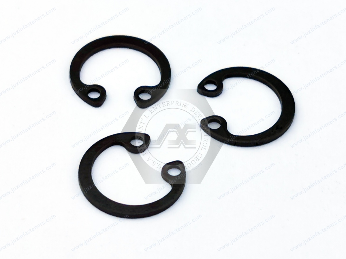
Axial force carried by the ring is transferred into the groove wall.
This means the housing material around the groove must be capable of supporting the load.
Potential concerns include:
groove-edge deformation;
housing shear;
local yielding;
brittle fracture;
groove damage.
A strong retaining ring installed in a weak housing does not create a strong retaining system.
A useful engineering concept is:
Retaining System Capacity = Limited by the Weakest Relevant Component
Depending on the design, the limiting condition may involve:
retaining-ring deformation;
ring failure;
groove deformation;
groove-edge failure;
housing material;
retained-component geometry.
Therefore:
Higher-Strength Ring ≠ Automatically Higher Assembly Capacity
Internal retaining rings are used to resist axial movement.
Engineers should therefore identify the expected axial force.
Potential sources include:
bearing thrust;
gear reaction;
spring force;
piston movement;
assembly preload;
transient mechanical loads.
The design should consider the actual load case rather than assuming every ring of the same nominal diameter has unlimited retention capability.
A constant axial force and repeated axial loading can create different design conditions.
Applications involving:
repeated load reversals;
shock;
cyclic thrust;
impact
may require additional evaluation.
Catalog or standard load information should be applied only within its defined assumptions.
A retaining ring may experience much higher instantaneous force during impact than during normal steady operation.
Applications involving:
reciprocating mechanisms;
mobile equipment;
transport equipment;
hydraulic motion;
mechanical stops
should consider possible transient loads.
Internal retaining rings are installed in bores, and some applications involve rotating housings or nearby rotating components.
Rotational speed may become relevant depending on the assembly architecture.
Do not assume that a retaining ring selected only from bore diameter is suitable for every high-speed rotating application.
A machined housing shoulder provides a continuous axial locating surface.
A retaining ring provides a removable retaining shoulder.
The two can be combined.
For example:
Housing Shoulder → Bearing → DIN 472 Ring
This arrangement can locate a bearing axially between a fixed shoulder and removable retaining ring.
Rolling bearings are one of the classic applications for internal retaining rings.
The design must consider:
bearing outer-ring dimensions;
housing bore;
groove location;
axial load;
assembly sequence;
serviceability.
The retaining ring should act on the intended component surface without interfering with bearing operation.
A retaining ring locates a component axially.
It does not automatically create controlled bearing preload.
If a bearing requires defined axial preload, the system may use additional components such as:
wave washers;
disc springs;
spacers;
precision shoulders.
Therefore:
Bearing Retention ≠ Bearing Preload
For bearing preload design, see the JUXIN FASTENERS Bearing Preload Wave Washers: Load, Working Height, Tolerance Stack & Selection Guide.
Internal circlips with installation holes are commonly installed using suitable retaining-ring pliers.
The general sequence is:
Confirm the correct ring and groove.
Inspect the groove and bore.
Engage the installation tool correctly.
Compress the ring only as much as required.
Insert the ring into the bore.
Position it at the groove.
Release the ring in a controlled manner.
Verify full seating.
The exact process should follow the applicable component and assembly requirements.
An internal retaining ring must be compressed during installation.
However:
Required Installation Compression ≠ Unlimited Compression
Excessive deformation can:
overstress the ring;
create permanent set;
damage the installation holes;
reduce dimensional recovery;
affect seating.
The installation tool should be appropriate for the ring size and geometry.
The holes at the ring ends allow installation pliers to engage the component.
They should not be treated as arbitrary pulling or lifting points.
Tool geometry and handling should minimize damage to these areas.
After installation, confirm that the ring is fully engaged around the groove.
A partially seated retaining ring can create a serious assembly risk.
Possible causes include:
incorrect groove dimensions;
contamination;
burrs;
wrong ring size;
excessive ring deformation;
incorrect installation.
Visual or process-controlled inspection can be important depending on the assembly.
Machining or forming burrs around the groove can interfere with ring installation.
Potential problems include:
partial seating;
ring distortion;
scratching;
unpredictable load transfer.
Groove quality is therefore part of retaining-system quality.
Some stamped retaining rings may have different edge characteristics resulting from manufacturing.
Whether orientation matters depends on:
ring design;
load direction;
assembly specification;
manufacturing characteristics.
Do not create a universal orientation rule without reference to the applicable product or engineering requirement.
Reuse should not automatically be assumed.
Before reuse, relevant considerations can include:
permanent deformation;
loss of spring recovery;
corrosion;
wear;
damaged installation holes;
edge damage;
previous over-expansion or over-compression.
For critical applications, follow the equipment or OEM maintenance specification.
Spring steel is commonly used because retaining rings require elastic deformation during installation followed by recovery into the groove.
The material and heat treatment must support the intended spring behavior.
However:
Spring Steel ≠ Automatic Corrosion Resistance
A suitable surface treatment may be required depending on the environment.
Stainless steel retaining rings may be considered for environments requiring improved corrosion resistance.
Material selection should consider:
mechanical properties;
spring behavior;
temperature;
chemical exposure;
mating materials.
Stainless steel should not be described as corrosion-proof.
Surface protection for retaining rings depends on:
material;
corrosion environment;
dimensional requirements;
assembly requirements;
customer specification.
For hardened spring-steel components, coating-process selection should also consider the risk of hydrogen embrittlement where applicable.
There is no universal coating solution for every retaining-ring application.
Understanding failure modes provides more engineering value than simply listing product advantages.
The ring leaves or partially leaves the groove under axial loading.
Potential causes can include:
incorrect groove;
insufficient engagement;
excessive axial load;
housing deformation;
incorrect ring selection.
The groove edge deforms or fails.
Potential causes include:
insufficient housing strength;
inadequate edge distance;
excessive axial load;
incorrect groove geometry.
The ring no longer returns to its intended geometry.
Potential causes include:
over-compression during installation;
incorrect tooling;
overload;
unsuitable material condition.
The ring is not fully engaged in the groove.
Potential causes include:
burrs;
contamination;
wrong size;
incorrect installation.
Corrosion can reduce the effective cross-section or interfere with installation and removal.
Improper pliers or excessive tool force can damage the ring ends.
A ring can physically enter the groove and still be wrong for the assembly.
Engineering validation should distinguish:
Dimensional Fit
from:
Functional Retention
A ring that fits may still have insufficient axial capacity or unsuitable material.
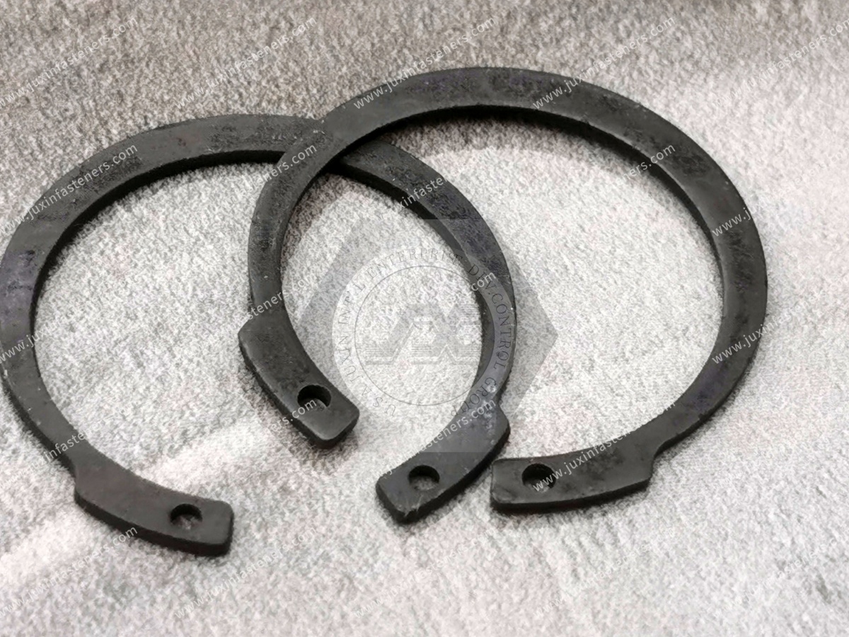
This is the most important standard distinction for buyers.
| Requirement | DIN 472 | DIN 471 |
|---|---|---|
| Installation location | Bore / housing | Shaft |
| Common description | Internal retaining ring | External retaining ring |
| Alternative term | Internal circlip | External circlip |
| Groove location | Inside bore | Outside shaft |
| Primary function | Axial retention in bore | Axial retention on shaft |
DIN 472 and DIN 471 should therefore occupy separate product and SEO pages.
The current DIN 472 recognizes normal and heavy types.
The heavy type should not simply be described as:
“the better version.”
Selection depends on the assembly requirements.
Consider:
axial force;
available groove geometry;
installation space;
housing dimensions;
applicable drawing.
If a customer drawing specifies one type, do not silently substitute the other.
Many existing drawings may still reference earlier DIN 472 editions.
The current 2026 edition replaced DIN 472:2017-06.
This creates a practical procurement issue:
Existing Drawing → Older DIN Edition → Current Supplier → Replacement Decision
For long-running OEM or MRO programs, confirm whether the customer requires:
exact legacy drawing compliance;
current DIN edition;
approved equivalent;
drawing revision.
Do not silently update a controlled customer specification.
Internal retaining rings may be used in selected:
electric motors;
gearboxes;
actuators;
pumps;
seat mechanisms;
auxiliary drive systems;
thermal-management equipment.
Safety-critical automotive assemblies require the applicable customer specifications and validation.
A generic DIN 472 ring should not automatically be represented as qualified for every automotive application.
Potential applications include retention of:
bearings;
sleeves;
internal components.
The ring can provide axial location while allowing relatively efficient assembly and service.
Bearing preload, if required, should be engineered separately.
Internal retaining rings may retain:
bearings;
sleeves;
gears;
spacers;
other internal components.
The design should consider actual thrust loads and groove strength.
Potential pump applications can include:
bearing retention;
internal mechanical component location;
serviceable subassemblies.
The retaining ring itself is not a fluid seal.
Internal retaining rings can be used to retain appropriate internal mechanical components.
Where pressure acts on a piston or component, axial force can be generated.
Conceptually:
Axial Force = Pressure × Effective Area
The resulting force must be considered by the complete retention system.
Do not assign a universal pressure rating to the retaining ring alone.
Similar principles apply to pneumatic systems.
The retaining ring may locate components, but the designer must convert system pressure and effective area into the relevant mechanical loading.
Potential applications include:
actuators;
gear units;
motors;
rollers;
bearing housings;
compact mechanisms.
Retaining rings can support compact assembly where threaded retention would require more axial space.
AI and HPC infrastructure contains mechanical equipment such as:
pumps;
fans;
blowers;
motors;
liquid-cooling equipment;
power equipment.
Internal retaining rings may be used within these components where their mechanical design requires axial retention.
However:
AI Data Center Application ≠ Special DIN 472 Requirement
The actual component design determines the retaining system.
Potential applications include:
motors;
blowers;
pumps;
actuators;
compressors;
mechanical drive assemblies.
DIN 472 rings can provide compact component retention where the equipment design uses a bore groove.
They do not automatically provide sealing or vibration isolation.
Potential applications include:
motors;
generators;
mechanical actuators;
auxiliary equipment.
Electrical qualification and mechanical retention should be treated separately.
DIN 472 internal retaining rings are particularly relevant to:
machine tools;
production machinery;
conveyor systems;
packaging equipment;
material-handling systems;
bearing housings;
mechanical drives.
Mobile equipment can contain retaining rings in:
hydraulic components;
bearings;
gear systems;
actuators;
mechanical subassemblies.
Shock and cyclic loading should be evaluated where relevant.
Retaining rings can be used in appropriate mechanical rail-equipment assemblies.
Safety-critical rail applications require the applicable design, qualification and customer requirements.
For marine equipment, material and coating selection should consider:
salt exposure;
moisture;
galvanic compatibility;
service environment.
A standard spring-steel ring should not automatically be assumed suitable for prolonged marine exposure.
Internal retaining rings can be used in appropriate non-sterile mechanical equipment such as:
laboratory instruments;
diagnostic equipment housings;
motors;
mechanical positioning systems.
Medical regulatory compliance should not be inferred from the retaining ring itself.
Industrial DIN 472 retaining rings should not automatically be represented as aerospace-qualified hardware.
Aerospace applications may require:
dedicated aerospace standards;
approved materials;
traceability;
special inspection;
qualified suppliers.
JUXIN FASTENERS can evaluate suitable drawing-based industrial, tooling, MRO and ground-support requirements subject to customer specifications.
| Design Condition | Engineering Consideration |
|---|---|
| Component inside bore | Internal retaining ring may be applicable |
| Component on shaft | Evaluate external retaining ring instead |
| DIN bore-retention requirement | Evaluate DIN 472 |
| High axial force | Check ring and groove capacity |
| Weak housing material | Groove may control the design |
| Bearing retention | Check bearing interface and thrust load |
| Bearing preload required | Use separate preload strategy |
| Repeated axial loading | Evaluate dynamic loading |
| Impact loading | Consider transient peak forces |
| Corrosive environment | Select appropriate material/finish |
| High-speed assembly | Review complete rotational system |
| Frequent disassembly | Evaluate serviceability and replacement |
| Custom groove | Validate ring/groove compatibility |
Bore size is only the starting point.
The groove is part of the load-bearing system.
DIN 472 is for bores; DIN 471 is for shafts.
Its primary function is axial retention.
The groove or housing may fail first.
This can permanently deform the ring.
Partial engagement can compromise retention.
Groove strength depends on the surrounding component.
Previous installation or service can alter the ring.
Heavy type and normal type should follow the actual engineering requirement.
Engineers may search:
DIN 472 retaining ring;
DIN 472 internal circlip;
internal retaining ring;
internal snap ring;
bore circlip;
retaining ring for bore;
DIN 472 groove dimensions;
internal circlip groove;
retaining ring axial load;
circlip pull-out failure;
bearing retaining ring;
internal circlip installation;
DIN 472 normal vs heavy type.
These searches usually indicate an active design, replacement or troubleshooting task.
Procurement teams may search:
DIN 472 supplier;
DIN 472 manufacturer;
internal retaining ring supplier;
internal circlip manufacturer;
bore circlip supplier;
stainless internal retaining ring;
spring steel circlip supplier;
custom retaining ring manufacturer;
DIN 472 bulk supplier;
OEM retaining ring supplier.
These searches carry stronger commercial intent.
For technical and commercial evaluation by JUXIN FASTENERS, provide where applicable:
DIN 472 designation;
standard edition where controlled;
normal or heavy type;
nominal bore size;
customer drawing;
ring dimensions;
groove drawing;
groove diameter;
groove width;
groove location;
housing material;
housing hardness where relevant;
retained component;
expected axial load;
static or cyclic load condition;
impact or shock condition;
rotational speed where relevant;
operating temperature;
corrosion environment;
ring material;
surface finish;
installation method;
removal/service requirement;
dimensional tolerances;
inspection requirement;
documentation requirement;
customer part number;
sample quantity;
prototype quantity;
production quantity;
estimated annual demand;
packaging requirement;
labeling requirement;
customer-specific requirements.
DIN 472 covers retaining rings for bores, commonly called internal retaining rings or internal circlips.
DIN 472:2026-05 is the current edition.
It replaced DIN 472:2017-06.
DIN 472 covers internal retaining rings for bores. DIN 471 covers external retaining rings for shafts.
Yes. The current standard covers normal type and heavy type retaining rings for bores.
Its primary function is to locate and retain a component axially inside a bore.
It should not be treated as a dedicated vibration-damping component.
Yes. Retaining rolling bearings in bores is a recognized application of this retaining-ring system.
Not automatically. Axial retention and controlled bearing preload are different engineering functions.
Not for every application. Groove geometry, axial load, housing material, ring type and operating conditions can also matter.
Yes. The groove or surrounding housing may become the limiting part of the retention system.
Reuse should follow the application or OEM maintenance requirements and should not automatically be assumed.
No. Stainless steel can improve corrosion resistance, but performance remains environment-dependent.
JUXIN FASTENERS can evaluate standard and drawing-based internal retaining-ring requirements according to size, type, material, finish, groove, quantity and customer specifications.
A buyer may initially send:
“Internal circlip for 40 mm bore, 50,000 pcs.”
That is useful, but it may not completely define the production requirement.
The supplier may still need to determine:
DIN 472 or Another Standard?
Which Standard Edition?
Normal or Heavy Type?
What Groove Geometry?
What Housing Material?
What Component Is Being Retained?
What Axial Load Must Be Transferred?
What Material Is Required?
What Surface Finish Is Required?
Is the Assembly Exposed to Corrosion?
Is Repeated Disassembly Expected?
The commercial path becomes:
Component → Bore → Axial Load → Groove → DIN 472 Type → Ring → Material / Finish → Installation → Validation → Production RFQ
This is the difference between purchasing a circlip that physically fits the bore and sourcing a retaining system that matches the mechanical assembly.
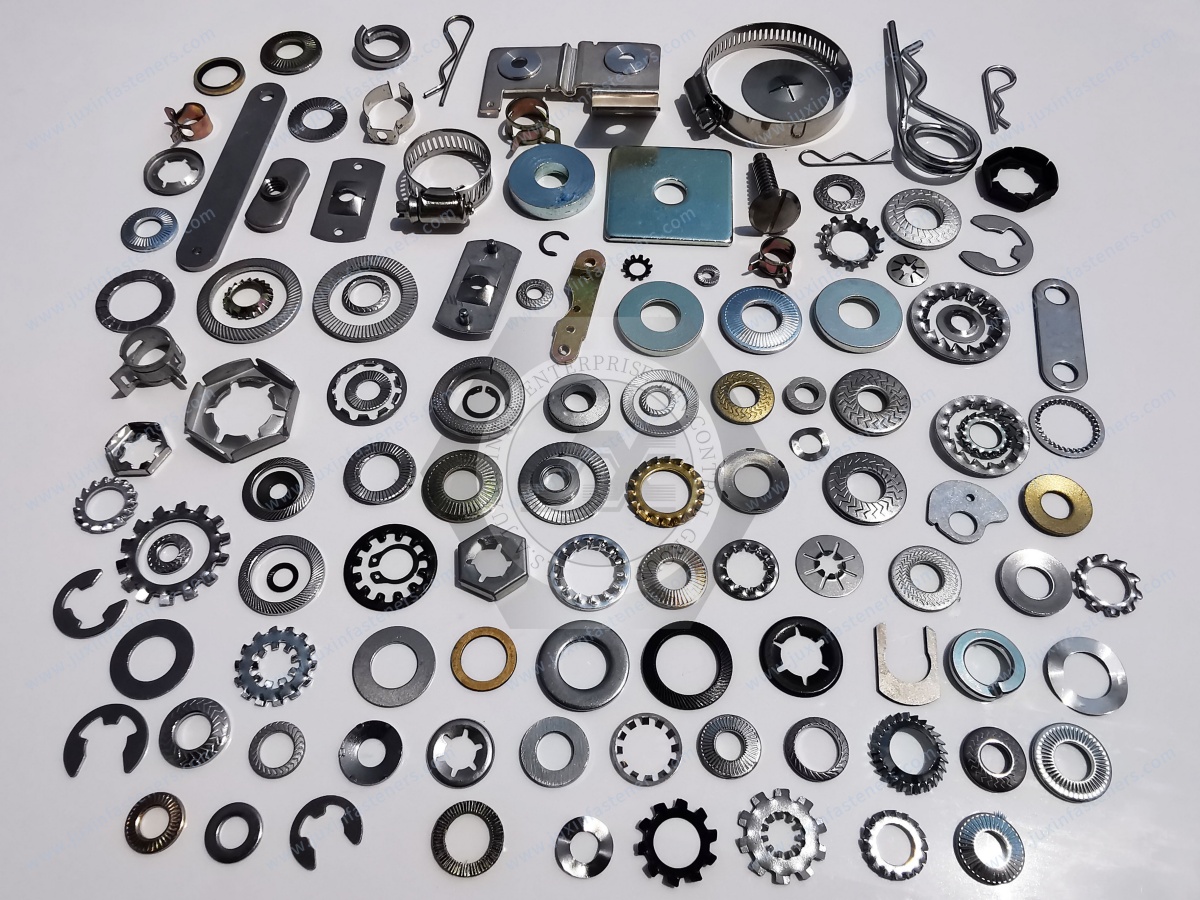
JUXIN FASTENERS supports OEM sourcing of:
DIN 472 internal retaining rings;
internal circlips;
internal snap rings;
bore retaining rings;
normal-type retaining rings;
heavy-type retaining rings;
spring-steel retaining rings;
stainless steel retaining rings;
drawing-based retaining components;
other industrial fastening and retention components.
Potential application sectors include:
industrial machinery;
automotive and EV equipment;
electric motors;
gearboxes;
pumps;
hydraulic equipment;
pneumatic equipment;
industrial automation;
robotics;
HVAC equipment;
AI data center and HPC cooling equipment;
power equipment;
construction machinery;
agricultural machinery;
rail-related equipment;
marine equipment.
For bearing preload applications, refer to the JUXIN FASTENERS Bearing Preload Wave Washers: Load, Working Height, Tolerance Stack & Selection Guide.
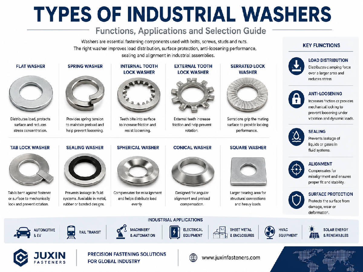
For broader washer and axial spring selection, see Industrial Washers: Types, Functions & Selection Guide.
For custom mechanical components, see Stainless Steel CNC Machining Parts.
For OEM DIN 472 internal retaining ring RFQs, send your DIN designation, drawing, bore size, groove dimensions, housing material, axial load, material, finish, quantity and estimated annual demand to:
For a reliable internal retaining-ring assembly, the most important question is not simply:
“Does the circlip fit the bore?”
It is:
“Can the ring, groove and housing work together to retain the component under the actual axial load?”
 MORE NEWS

Sep. 27, 2026

Sep. 27, 2026

Sep. 27, 2026
Contact Us
Tel.:
+86 020 8621 0320
+86 020 3121 6067
E-mail:
Technical Support:
Navigation
SEND INQUIREY