
Call Us
+86 136 6007 9809
Call Us
+86 136 6007 9809

Oct. 16, 2023
Internal retaining rings, also known as internal circlips, bore retaining rings, internal snap rings or retaining rings for bores,
are compact mechanical fasteners used to axially retain components inside housings, cylinders and other machined bores.
Unlike external retaining rings that fit around shafts, an internal retaining ring is compressed during installation, inserted into a bore and released into a machined internal groove.
Once correctly seated, the ring creates a mechanical shoulder that can restrict axial movement of components such as:
Bearings
Bushings
Pistons
Seals and supporting components
Sleeves
Mechanical cartridges
Rollers
Valve components
Actuator components
Other bore-mounted parts
Internal retaining rings are widely used where engineers need reliable axial retention without adding threaded retainers, end plates or other bulky fastening structures.
However, the retaining ring should not be treated as an isolated component.
A reliable internal retaining system should be evaluated as:
Retained Component + Internal Retaining Ring + Housing Groove + Housing Material + Axial Load + Tolerance Stack + Installation Method + Operating Environment
This system-level approach is particularly important for automotive, EV, industrial machinery, robotics, automation, rail transit,
HVAC, electrical equipment, telecommunications equipment, semiconductor equipment, medical equipment, food-service equipment and other OEM applications.
An internal retaining ring is a spring-type fastener designed to fit into a groove machined inside a bore or housing.
In its free condition, the ring is larger than the installation diameter required to pass through the bore. During installation, suitable tooling compresses the ring so it can enter the housing.
When aligned with the groove and released, the ring expands toward its free condition and engages the groove.
The resulting ring projection into the bore creates an axial retaining shoulder.
This is fundamentally different from relying on friction alone.
The component is mechanically restricted by the retaining ring and the groove supporting it.
The distinction is simple but essential.
Installed inside a bore or housing.
During installation, the ring is generally compressed.
Typical purpose:
Retain a component inside a housing.
Installed around a shaft.
During installation, the ring is generally expanded.
Typical purpose:
Retain a component on a shaft.
Confusing the two architectures can lead to incorrect part selection, groove design and installation tooling.
For broader comparison, engineers can review our guide to Retaining Rings for Shafts and Bores.
Different engineering organizations, industries and purchasing teams use different terminology for similar components.
Common search and RFQ terms include:
Internal retaining ring
Internal circlip
Internal snap ring
Bore retaining ring
Retaining ring for bore
Retaining ring for housing
Internal retaining clip
Internal spring retaining ring
Bearing housing circlip
Internal snap ring for bearing
DIN 472 retaining ring
When sourcing replacement parts, terminology alone is not sufficient.
A drawing, applicable standard, housing dimensions, groove dimensions or physical sample provides a much more reliable basis for identification.
DIN 472 is widely associated with retaining rings for bores.
Standardized internal retaining rings can provide significant advantages for OEM design and procurement:
Established dimensional architecture
Standardized nominal sizes
Easier sourcing
Easier replacement
Reduced need for custom tooling
Simplified drawing communication
Greater second-source flexibility
However, not every internal retaining ring is necessarily a DIN 472 part.
Existing assemblies may contain:
Modified standard rings
Heavy-section retaining rings
Reduced-lug designs
Special installation geometries
Custom thicknesses
Non-standard groove relationships
Drawing-specific retaining rings
Therefore, engineers should distinguish between a general internal retaining ring and a specific DIN 472 retaining ring.
For standard-specific selection, dimensional requirements and sourcing, see our dedicated DIN 472 Retaining Rings for Bores resource.
Understanding the load path is one of the most important aspects of retaining-ring design.
A simplified internal retaining system transfers axial load through:
Retained Component → Retaining Ring → Housing Groove → Housing
This means the ring itself is only one part of the load-bearing system.
The actual retention capability may depend on:
Retaining-ring geometry
Ring material
Ring hardness
Groove geometry
Groove-edge strength
Housing material
Housing hardness
Component contact geometry
Axial load direction
Static or cyclic loading
Shock loading
Installation condition
A stronger ring does not automatically create a stronger retaining system if the housing groove becomes the limiting feature.
The groove is the structural interface between the retaining ring and the housing.
Important groove parameters include:
Groove diameter
Groove width
Groove depth
Groove location
Groove tolerance
Edge geometry
Surface condition
Distance from the housing end
Housing wall thickness
Housing material
Housing hardness
An incorrectly machined groove can compromise the complete assembly even when the retaining ring itself meets specification.
Potential consequences include:
Incomplete seating
Excessive axial movement
Ring distortion
Groove-edge deformation
Ring disengagement
Difficult assembly
Difficult removal
Reduced retention capability
For this reason, an OEM retaining-ring RFQ should include groove information whenever possible.
A groove positioned close to the end of a housing deserves particular engineering attention.
Axial load transferred through the retaining ring must ultimately be supported by the housing material surrounding the groove.
If insufficient material remains between the groove and the housing edge, the limiting failure mode may involve the housing rather than the retaining ring.
Engineers should therefore evaluate the relationship between:
Groove position
Housing-end distance
Housing material
Wall thickness
Axial load
Component contact geometry
This is an important example of why retaining-ring selection cannot be reduced to choosing a nominal bore diameter.
Another common sourcing mistake is treating ring thickness and groove width as interchangeable dimensions.
The groove must provide enough space for the retaining ring to seat and function as intended, while the completed assembly must meet its required axial-clearance condition.
The relationship can be affected by:
Ring thickness tolerance
Groove-width tolerance
Component-width tolerance
Groove-location tolerance
Surface coating
Manufacturing variation
The correct relationship should follow the applicable standard or approved engineering drawing.
A retaining ring creates an axial stop, but it does not automatically eliminate axial clearance.
Final component movement can depend on the entire dimensional stack:
Housing Shoulder + Component Width + Groove Location + Groove Width + Ring Thickness + Spacer / Shim + Adjacent Components
This matters particularly in assemblies containing:
Bearings
Precision bushings
Mechanical cartridges
Valve components
Actuator components
Position-sensitive mechanisms
If tightly controlled axial position or preload is required, the retaining ring may need to work with additional locating components.
A conventional internal retaining ring provides mechanical retention.
It should not automatically be described as:
Waterproof
Dustproof
Liquid-tight
Gas-tight
Pressure-sealing
If an assembly requires environmental or pressure sealing, the sealing function normally needs to be engineered separately using an appropriate sealing component and interface.
This distinction is particularly important in:
Hydraulic equipment
Pneumatic equipment
Pumps
HVAC systems
Food-service equipment
Medical equipment
Outdoor equipment
The retaining ring may help position a seal or retain a sealing component, but that does not make the ring itself a seal.
A retaining ring can maintain axial position in equipment exposed to vibration, but its primary purpose is mechanical retention.
It should not automatically be specified as a vibration-damping component.
If vibration isolation or damping is required, engineers should evaluate dedicated components such as:
Elastomeric elements
Spring elements
Damping materials
Isolation mounts
Other engineered damping systems
The retaining ring should instead be evaluated for its ability to remain correctly seated and maintain the intended axial retention under the expected operating conditions.
Material selection affects:
Elastic behavior
Strength
Fatigue performance
Wear
Corrosion resistance
Temperature capability
Manufacturing process
Cost
Common material families include:
Spring steels are widely used for industrial retaining rings because they can provide a useful combination of:
Strength
Hardness
Elastic recovery
Wear resistance
Manufacturing efficiency
Final performance depends on the complete manufacturing process, including forming, heat treatment, hardness control and surface finishing.
Stainless retaining rings may be selected where corrosion resistance is important.
Potential applications include:
Food-service equipment
Medical equipment
Laboratory equipment
HVAC equipment
Outdoor machinery
Telecommunications equipment
Semiconductor equipment
Pumps and fluid-handling equipment
Material selection should reflect the actual operating environment.
A stainless designation alone does not establish suitability for every chemical, chloride, temperature or cleaning condition.
Certain projects may require alternative alloys due to:
Elevated temperature
Aggressive corrosion
Magnetic requirements
Special mechanical requirements
Customer material specifications
These applications should normally be treated as drawing-based engineering projects rather than assumed to follow a standard commercial retaining-ring specification.
Carbon and alloy steel rings may require surface protection.
Depending on the application and customer specification, finish options can include:
Phosphate and oil systems
Black finishes
Zinc-based coatings
Zinc-nickel systems
Zinc-flake coating systems
Other engineered finishes
The selected coating should be evaluated for:
Corrosion requirement
Base material
Component hardness
Hydrogen-embrittlement considerations where applicable
Coating thickness
Dimensional impact
Groove fit
Installation behavior
Customer restricted-substance requirements
Surface treatment should therefore be specified as part of the engineering requirement rather than added only for appearance.
Retaining rings operate within relatively controlled groove geometry.
A change in surface coating may change finished dimensions or friction characteristics.
For precision assemblies, coating selection can influence:
Effective ring thickness
Groove clearance
Installation force
Seating behavior
Removal behavior
Corrosion performance
This becomes especially important during OEM second-source development when a replacement part must function in an existing groove.
A structured selection process can reduce assembly problems.
Determine the nominal housing size and the applicable dimensional architecture.
What must the ring retain?
Examples include:
Bearing
Bushing
Seal carrier
Piston
Sleeve
Mechanical cartridge
Roller
Valve component
Consider:
Load magnitude
Load direction
Static loading
Cyclic loading
Reversing loading
Shock loading
Verify:
Groove diameter
Groove width
Groove depth
Groove location
Tolerances
Consider:
Housing material
Hardness
Wall thickness
Groove-to-edge distance
Available installation access
Evaluate the complete tolerance stack rather than the retaining ring alone.
Match the retaining ring to:
Corrosion environment
Temperature
Humidity
Chemical exposure
Service life
Customer specifications
Confirm that suitable installation tooling can access the ring inside the actual assembly.
Where the application involves significant axial load, shock, high cycling or critical equipment, prototype and assembly validation may be appropriate.
Internal retaining rings are generally compressed for installation.
A typical installation process is:
Verify the retaining ring specification.
Inspect the ring for distortion or damage.
Inspect and clean the housing groove.
Use suitable internal circlip installation tooling.
Compress the ring only as much as required.
Insert it into the housing.
Align the ring with the groove.
Release it carefully.
Verify complete seating around the groove.
The correct tooling depends on ring design, size, production volume and assembly accessibility.
Internal retaining rings are elastic components, but elastic travel is not unlimited.
Excessive compression during installation can cause permanent deformation.
Possible consequences include:
Reduced free diameter
Distorted geometry
Poor groove engagement
Uneven seating
Reduced retention reliability
Production tooling should therefore control the installation process rather than compressing the ring more than necessary.
Stamped retaining rings may have different edge characteristics as a result of the manufacturing process.
Depending on the ring design and application, engineers may need to consider the relationship between:
Load direction
Stamped edge condition
Component contact face
Groove contact
Installation orientation
The correct orientation should follow the applicable standard, drawing or validated assembly requirement.
This is more reliable than applying a universal orientation rule to every retaining-ring design.
Reuse should be evaluated rather than assumed.
Removal and reinstallation can affect:
Ring geometry
Elastic recovery
Lug condition
Surface finish
Coating
Installation damage
For non-critical service assemblies, reuse may be permitted by the equipment specification.
For critical or production applications, the maintenance or engineering specification should define whether replacement is required after removal.
When a bore-mounted component develops excessive axial movement, the ring should not automatically be blamed.
A structured failure review should consider several possibilities.
The ring may not correspond to the groove architecture.
A groove that is too shallow, too deep, too wide or incorrectly located can prevent proper retention.
Part of the ring may remain outside the groove.
Excessive compression or incorrect tooling can distort the ring.
The housing material may deform under axial load.
The operating load may exceed the capability of the complete ring-and-groove system.
Corrosion can affect the ring, groove or seating condition.
Excessive axial movement may originate from the overall assembly dimensions rather than from retaining-ring failure.
A ring with unsuitable mechanical properties may not maintain the required geometry after installation.
This system-level troubleshooting approach provides more useful information than simply replacing the ring with a thicker component.
Bearing retention is one of the most important applications for internal circlips.
An internal retaining ring can provide an axial stop for a bearing outer ring installed inside a housing.
Typical applications include:
Electric motors
Gearboxes
Pumps
Rollers
Actuators
Gear motors
Industrial machinery
However, the bearing arrangement must be considered as a complete system.
Engineers should review:
Bearing outer-ring geometry
Bearing chamfer
Housing shoulder
Groove position
Ring contact
Axial clearance
Operating load
For a detailed discussion, see our Bearing Retaining Rings: Shaft & Bore Circlips for Axial Bearing Retention guide.
Internal retaining rings can be found in suitable automotive and electrification-related mechanical assemblies such as:
Electric motors
Pumps
Actuators
Transmission mechanisms
Thermal-management equipment
Seat mechanisms
Steering-related mechanisms
Auxiliary drive systems
Production equipment
The end-use industry alone does not determine the correct ring.
Actual geometry, load, material, environment and customer specifications should control selection.
Industrial equipment contains numerous bore-mounted components requiring compact axial retention.
Applications may include:
Gearboxes
Pumps
Reducers
Machine tools
Conveyors
Rollers
Packaging machinery
Processing equipment
Material-handling systems
Retaining rings can reduce component count where the mechanical architecture permits a groove-based retention system.
Compact packaging makes internal retaining rings useful in:
Robotic joints
Actuators
Gear mechanisms
Grippers
Positioning systems
Automated assembly equipment
Material-handling equipment
High-cycle systems may require additional evaluation of fatigue, groove wear and production consistency.
Potential applications include mechanical assemblies within:
Door systems
Actuators
Auxiliary mechanisms
Seat mechanisms
Control systems
Maintenance equipment
Project-specific requirements for vibration, fatigue, documentation and traceability should be defined before production.
Internal retaining rings may be used in:
Pumps
Fans
Blowers
Motors
Compressors
Valve actuators
Cooling equipment
Humidity, condensation and chemical exposure may influence material and coating selection.
Modern data-center infrastructure increasingly depends on high-capacity thermal-management equipment.
Internal retaining rings may appear within mechanical subassemblies such as:
Pumps
Motors
Fans
Blowers
Valve actuators
Cooling distribution equipment
Liquid-cooling equipment
The correct retaining ring should be selected from the actual mechanical design rather than from the data-center application name.
Potential applications include mechanical assemblies within:
Cooling fans
Electric motors
Actuators
Ventilation systems
Mechanical drives
Auxiliary equipment
Internal retaining rings can provide compact axial retention where housing-based groove designs are appropriate.
Internal retaining rings may be used in mechanical subassemblies within:
Cooling equipment
Fans
Motors
Antenna adjustment mechanisms
Actuators
Outdoor communication equipment
For outdoor equipment, corrosion resistance may become an important sourcing parameter.
Precision automation and motion systems used in semiconductor equipment can contain:
Bearings
Rollers
Motors
Pumps
Actuators
Robotic mechanisms
Positioning systems
If a project requires special cleanliness, vacuum compatibility or process restrictions, those requirements must be separately defined.
A standard commercial retaining ring should not automatically be represented as semiconductor- or cleanroom-qualified.
Potential applications include:
Commercial mixers
Refrigeration systems
Pumps
Motors
Conveyors
Dispensing equipment
Food-processing machinery
Cleaning chemicals, humidity and washdown exposure can influence material selection.
Use in food-service equipment does not automatically establish suitability for direct food contact.
Potential non-implant applications include:
Diagnostic equipment
Laboratory automation
Pumps
Actuators
Positioning equipment
Sample-handling systems
Special requirements for material traceability, cleanliness or documentation should be specified in the RFQ.
Internal retaining rings can also be used in suitable:
Hydraulic equipment
Actuators
Pins and pivot assemblies
Cylinders
Mechanical linkages
Construction machinery subassemblies
High shock loading or heavy axial loads should be evaluated against the complete retaining architecture.
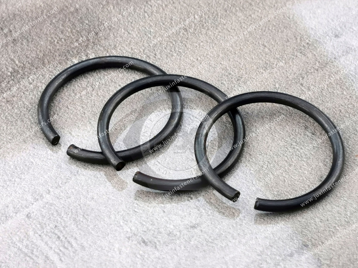
Compact retaining rings can be used in:
Small motors
Measuring instruments
Cooling fans
Rollers
Mechanical indicators
Adjustment mechanisms
Electronic appliances
Electromechanical devices
For miniature assemblies, small dimensional changes can significantly affect groove engagement and installation behavior.
Standard retaining rings are often the preferred starting point because they simplify:
Engineering
Procurement
Replacement
Supplier development
Inventory management
However, custom internal retaining rings may be required when an assembly contains:
Non-standard bore diameter
Existing custom groove
Restricted installation access
Special ring thickness
Special lug geometry
Special material
Special coating
Legacy component geometry
Customer-specific load requirement
The sourcing path should therefore distinguish between:
Standard Internal Retaining Ring
Standard-Based Modified Ring
Drawing-Based Replacement Ring
Functional Equivalent
Fully Custom Internal Retaining Ring
OEM second-source and maintenance projects sometimes begin with only a physical sample.
A practical development route is:
Sample → Dimensional Inspection → Groove Review → Material / Finish Evaluation → Drawing Confirmation → Prototype → Assembly Validation → Pilot Production → Production
However, a sample cannot reliably reveal every original design requirement.
Additional information may still be needed for:
Material specification
Heat treatment
Hardness
Surface treatment
Design axial load
Fatigue requirement
Environmental exposure
Original dimensional standard
Whenever possible, provide both the sample and application information.
Engineers searching for internal retaining rings may use queries such as:
Internal retaining ring
Internal circlip
Internal snap ring
Retaining ring for bore
Bore retaining ring
Circlip for housing
Internal circlip groove
Internal snap ring groove
Bearing housing retaining ring
DIN 472 retaining ring
How to retain a bearing in a housing
How to select an internal circlip
The underlying engineering question is usually:
How can I reliably retain this component inside the housing within the available space, load and tolerance conditions?
Purchasing teams may search for:
Internal retaining ring manufacturer
Internal circlip supplier
Bore retaining ring supplier
DIN 472 retaining ring supplier
Stainless internal circlip manufacturer
Custom internal snap rings
OEM retaining ring manufacturer
Retaining ring second source
Custom circlip from drawing
Their underlying question is:
Can this supplier reproduce the required geometry, material, heat treatment, finish and production consistency for our assembly?
A useful B2B product resource should answer both engineering and sourcing questions.
For faster engineering review and quotation, provide the following information where available.
Applicable standard
Customer drawing
Existing part number
Physical sample
Nominal bore size
Groove diameter
Groove width
Groove depth
Groove location
Groove tolerances
Housing material
Hardness where relevant
Wall thickness
Groove-to-edge distance
Component type
Component dimensions
Contact geometry
Required axial position
Acceptable axial clearance
Axial load
Static or cyclic loading
Shock
Vibration
Rotational conditions where relevant
Required service life
Required ring material
Hardness specification
Surface treatment
Corrosion requirement
Restricted-substance requirements
Temperature
Humidity
Outdoor exposure
Chemicals
Cleaning agents
Other corrosive media
Prototype quantity
Pilot quantity
Production quantity
Estimated annual volume
Packaging
Traceability
Required delivery schedule
For OEM and Tier supply chains, supplier evaluation may need to extend beyond part price.
Depending on the project, relevant capabilities can include:
Drawing interpretation
Material control
Forming-process control
Heat-treatment control
Hardness verification
Dimensional inspection
Surface-treatment control
Prototype development
Production consistency
Lot identification
Packaging control
Engineering-change management
Long-term supply continuity
For an existing production assembly, fit and functional validation against the actual groove can be especially important when qualifying a second source.
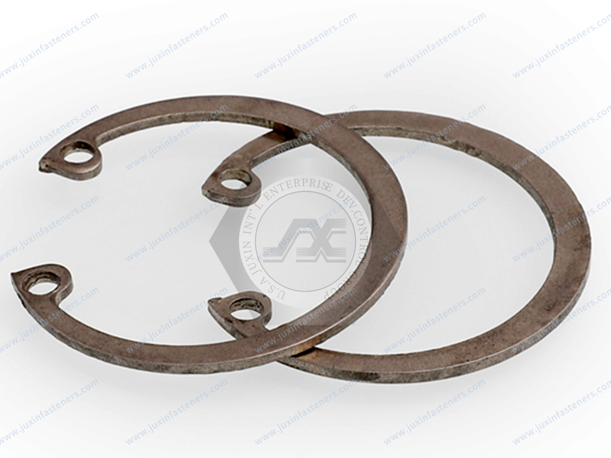
A practical selection path is:
What component must be retained?
→ Is it retained inside a housing or on a shaft?
→ What bore diameter is available?
→ Can a standardized internal retaining ring be used?
→ What axial load reaches the ring?
→ What housing material supports the groove?
→ What groove geometry is available?
→ Is the groove sufficiently supported by the housing?
→ What axial clearance is acceptable?
→ What installation access is available?
→ Will the ring require service removal?
→ What corrosion and temperature conditions exist?
→ What material and coating are appropriate?
→ Is DIN 472 appropriate?
→ Is a modified or custom internal retaining ring required?
This decision process is more reliable than selecting a retaining ring from bore diameter alone.
For a broader overview of retaining-ring families and selection logic, review Elastic Retaining Rings & Circlips: Types, Selection, Groove Design and Industrial Applications.
For standardized bore rings, continue to DIN 472 Retaining Rings for Bores.
For comparison between shaft and bore architectures, review Retaining Rings for Shafts and Bores.
For bearing-specific applications, see Bearing Retaining Rings: Shaft & Bore Circlips for Axial Bearing Retention.
For radial shaft installation, review E-Type Retaining Rings for Shafts.
For non-standard dimensions, legacy components and drawing-based development, continue to Custom Retaining Rings & Spring Fasteners.
JUXIN FASTENERS supports internal retaining ring, internal circlip, bore snap ring and custom spring-fastener sourcing projects for industrial OEMs,
engineering teams, purchasing organizations and supplier-development programs.
Projects can be evaluated from:
International standard
Customer drawing
Existing sample
Bore dimensions
Groove dimensions
Retained component
Material specification
Surface finish
Application conditions
Production volume
Depending on the project, the sourcing path may involve:
Standard Internal Circlip → DIN 472 Retaining Ring → Standard-Based Modified Ring → Drawing-Based Replacement → Custom Internal Retaining Ring
The most effective sourcing process starts with the assembly rather than the product name:
Retained Component → Bore → Groove → Axial Load → Housing Material → Tolerance Stack → Retaining Ring → Material → Finish → Installation → Validation → Production
This converts a generic inquiry such as:
“Please quote an internal circlip.”
into an engineering RFQ that a manufacturer can evaluate:
“Please evaluate an internal retaining ring for this housing bore, groove geometry, retained component, axial load, material, operating environment and production requirement.”
For internal retaining rings, internal circlips, bore retaining rings, internal snap rings, DIN 472 retaining rings, stainless steel circlips, spring steel retaining rings,
drawing-based replacement rings, custom retaining rings or OEM second-source development, send your drawing, sample, bore dimensions, groove dimensions, material, finish, application requirements and quantity to:
JUXIN FASTENERS can review the available technical information and evaluate an appropriate standard, manufacturing, sampling and production path for your project.
 MORE NEWS

Sep. 27, 2026

Sep. 27, 2026

Sep. 27, 2026
Contact Us
Tel.:
+86 020 8621 0320
+86 020 3121 6067
E-mail:
Technical Support:
Navigation
SEND INQUIREY