
Call Us
+86 136 6007 9809
Call Us
+86 136 6007 9809

Jun. 20, 2023
Automotive Fasteners, Blind Rivets, EV Battery Sealing and Precision CNC Shaft Engineering Guide
Modern automotive, electric vehicle and industrial machinery manufacturers require fastening systems that deliver reliable mechanical performance, corrosion resistance and efficient production assembly.
Fastener selection is no longer limited to choosing a nominal diameter, material grade or standard component.
Engineers must evaluate the complete joint, including substrate properties, environmental exposure, installation conditions, dimensional tolerances and long-term performance.
For automotive chassis assemblies, blind rivets must withstand specified mechanical loads and operating conditions.
For electric vehicle battery enclosures, rivet nuts must provide reliable threaded retention while remaining compatible with the enclosure sealing design.
For precision rotating equipment, CNC-machined shafts must meet functional dimensional, geometric and surface-finish requirements.
This engineering guide examines automotive fastener corrosion protection, blind rivet selection, EV battery enclosure fastening and precision CNC-machined shaft manufacturing.
It also addresses the technical and commercial considerations involved in OEM supplier development, production planning, quality verification and international sourcing.
Automotive Fastener Corrosion Protection and Environmental Selection
Automotive fasteners operate in different corrosion environments depending on their installation location.
A fastener installed inside a protected passenger compartment has different environmental requirements from a component installed beneath a vehicle, near a wheel assembly or in an exposed electrical enclosure.
Relevant exposure conditions include road salt, moisture, chloride contamination, mud, thermal cycling, abrasion, coating damage and contact between dissimilar metals.
The correct protective finish must be selected according to the operating environment, base material, joint design and customer specification.
Zinc-Nickel Coatings
Zinc-nickel coatings are used in selected automotive and industrial applications requiring corrosion protection on steel components.
ISO 19598 may be relevant to specified zinc and zinc-alloy coating systems on iron or steel.
Important characteristics include coating composition, thickness, passivation, topcoat, corrosion acceptance criteria, thread tolerance and friction behavior.
For high-strength steel components, hydrogen embrittlement controls must also be considered where applicable.
Zinc-nickel coatings may be evaluated for suitable automotive bolts, nuts and other steel fastening components.
However, a generic zinc-nickel designation does not guarantee a specific salt spray duration or service life.
Zinc-Flake Coatings
Non-electrolytically applied zinc-flake coatings are used on selected automotive bolts, screws, nuts and other steel fasteners.
ISO 10683 is relevant to applicable zinc-flake coating systems.
Engineering considerations include corrosion protection, coating thickness, adhesion, friction behavior, thread fit and manufacturing compatibility.
For high-strength fasteners, the complete coating process should also be evaluated for hydrogen embrittlement risk.
A coating change may alter tightening friction and therefore affect the relationship between installation torque and bolt preload.
Electroplated Zinc Coatings
Electroplated zinc may be appropriate for selected protected or moderately exposed industrial applications.
ISO 4042 provides requirements for applicable electroplated coatings on fasteners.
Selection depends on environmental exposure, coating thickness, base material, mechanical properties and customer requirements.
For high-strength steel fasteners, the plating process and hydrogen embrittlement risk require particular attention.
High-Temperature Fastener Protection
Fasteners exposed to elevated temperatures may require specialized materials and surface treatments.
Potential applications include exhaust-related equipment, thermal processing machinery and other high-temperature assemblies.
Engineers should evaluate operating temperature, exposure duration, oxidation, mechanical strength retention, thermal expansion and thread galling.
Copper plating or anti-seize compounds should not be treated as universal high-temperature corrosion solutions.
Automotive Corrosion Protection Selection Matrix
| Operating Environment | Potential Coating Approach | Engineering Verification |
|---|---|---|
| Road-salt-exposed steel fasteners | Qualified zinc-nickel or zinc-flake system | Corrosion resistance, friction and coating integrity |
| Exterior automotive brackets | Suitable zinc-based protective finish | Environmental and assembly compatibility |
| Protected interior equipment | Appropriate electroplated zinc or other finish | Customer specification and actual exposure |
| High-temperature assemblies | Temperature-compatible material and treatment | Thermal and mechanical performance |
| Steel-to-aluminum joints | Compatible coating and interface protection | Galvanic corrosion and joint function |
| Electrical grounding connections | Application-specific conductive protection | Electrical continuity and corrosion |
These are engineering selection considerations rather than guaranteed coating performance values.
ISO 9227 and ASTM B117 Salt Spray Testing
ISO 9227 and ASTM B117 are widely used laboratory salt spray test methods.
They define controlled exposure conditions but do not independently establish a universal corrosion-resistance requirement for every fastener coating.
A complete corrosion specification should identify the applicable test method, coating system, exposure duration, specimen condition, acceptance criteria and evaluation procedure.
For zinc-coated steel components, specifications may distinguish white corrosion products from red rust.
However, the applicable criteria depend on the coating system and customer specification.
Salt spray testing does not directly predict the service life of a fastener in every automotive environment.
Actual exposure may include cyclic wetting and drying, mechanical abrasion, temperature changes, galvanic coupling and coating damage.
Where an OEM requires cyclic corrosion testing, the applicable procedure should be specified separately.
Galvanic Corrosion in Steel-to-Aluminum Automotive Joints
Electric vehicle structures frequently combine aluminum sheets, extrusions and castings with steel fastening components.
When dissimilar metals are electrically connected in the presence of an electrolyte, galvanic corrosion may occur.
The severity depends on the material combination, relative exposed surface areas, moisture, chloride exposure, coating condition and joint geometry.
Potential mitigation measures include compatible protective coatings, interface materials, sealants and appropriate joint design.
However, electrical isolation may conflict with required grounding or bonding functions.
For electrical connections, corrosion protection and electrical conductivity must be evaluated together.
The coating should therefore be qualified for the assembled joint rather than only for the isolated fastener.
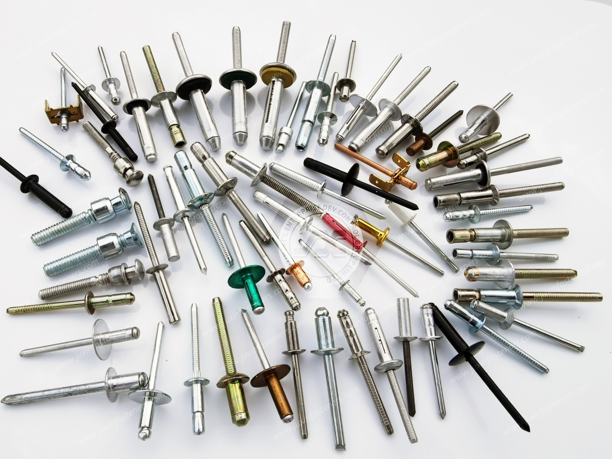
Blind Rivet Classifications and Mechanical Selection
Blind rivets provide permanent mechanical fastening where installation access is available from only one side.
They are used in suitable sheet-metal assemblies, industrial enclosures, automotive components, machinery brackets and selected composite structures.
The correct rivet depends on parent material, joint thickness, hole diameter, grip range, load direction, installed geometry and installation equipment.
Standard Breakstem Blind Rivets
Standard breakstem blind rivets are commonly used for general sheet-metal fastening.
Their performance depends on the rivet body material, mandrel material, diameter, grip range and installation quality.
Important requirements include correct hole size, suitable grip range, adequate shear and tensile capacity, compatible installation tooling and proper blind-side formation.
Bulbed Blind Rivets
Bulbed blind rivets form an enlarged blind-side bearing region during installation.
Depending on the product, this may distribute load over a wider area.
Potential applications include thin sheet metal, commercial vehicle panels and industrial equipment.
The actual installed geometry and mechanical capacity must be verified for the selected rivet.
Peel-Type and Lantern Blind Rivets
Peel-type or lantern-style blind rivets form expanded blind-side features that may help distribute load in suitable soft substrates.
Potential applications include plastic panels, fiberglass, composite structures, thin sheet metal and interior equipment panels.
The larger blind-side contact area may reduce localized bearing stress.
However, installation force must remain compatible with the substrate.
A rivet that expands over a wider area can still damage brittle materials if hole geometry or setting conditions are incorrect.
Specialty Pull-Through Rivets
Certain specialty blind rivets use mandrel and body configurations that differ from conventional breakstem designs.
Because terminology varies among product families, the exact drawing and installation specification should be used when evaluating a pull-through rivet.
The term alone does not establish a universal mechanical category with identical performance characteristics.
Blind Rivet Selection Matrix
| Rivet Type | Main Characteristic | Selection Consideration |
|---|---|---|
| Standard breakstem | General one-sided installation | Correct grip range and load |
| Bulbed | Enlarged blind-side bearing region | Thin-sheet support |
| Peel-type | Expanded or divided blind-side formation | Soft or sensitive substrates |
| Specialty pull-through | Product-specific installation mechanism | Drawing and process verification |
| Sealed blind rivet | Designed to reduce certain leakage paths | Complete joint sealing validation |
Blind Rivet Grip Range, Hole Geometry and Substrate Protection
A blind rivet must be matched to the complete material stack.
Grip range defines the permitted assembled thickness for a specified rivet.
A rivet installed outside its validated grip range may not form the intended blind-side head.
This can reduce retention or damage the joint.
Incorrect hole dimensions can affect alignment, bearing stress and installed head formation.
The required hole diameter and edge distance should follow the selected product and joint design.
Shear, tensile and pull-through resistance are different mechanical characteristics.
A rivet suitable for a shear-loaded connection may not be suitable for a joint exposed to significant tensile separation.
Composite and polymer panels may be vulnerable to local crushing, hole enlargement, delamination, cracking and creep.
The installation process should be validated against the actual substrate.
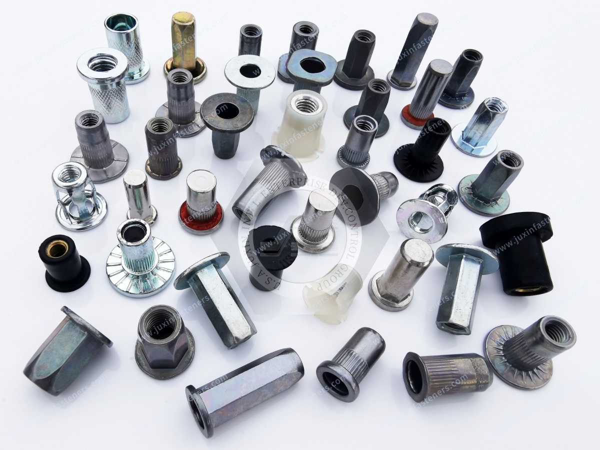
EV Battery Enclosure Fastening with Blind Rivet Nuts
Blind rivet nuts provide internal threads where conventional nuts or tapped threads may be impractical.
Potential EV battery applications include enclosure brackets, service covers, cable-management supports, cooling-system brackets, electrical equipment mounting and protective shields.
The selection depends on enclosure geometry, parent material, installation access and required joint performance.
Open-End and Closed-End Rivet Nuts
Open-end rivet nuts contain a through-threaded opening.
Closed-end rivet nuts incorporate a closed body end and may reduce leakage through the insert itself.
However, a closed-end body does not automatically seal the interface between the insert and the parent sheet.
Additional sealing measures may be required.
Round-Body Rivet Nuts
Round-body rivet nuts are installed in suitable circular holes.
Retention depends on the body geometry, substrate and installation conditions.
Knurled configurations may provide additional anti-rotation engagement in suitable materials.
Half-Hex and Full-Hex Rivet Nuts
Half-hex and full-hex rivet nuts can provide geometric anti-rotation engagement in correctly prepared holes.
However, actual torque-out resistance depends on hole geometry, parent material, grip range, body design and installation conditions.
A hexagonal body does not automatically prevent local aluminum deformation.
Double-Layer Aluminum Rivet Nut Installation
EV battery enclosures and lightweight vehicle structures may contain multiple aluminum layers.
Installing a blind rivet nut through such a stack requires evaluation of how the setting force is transferred through the layers.
Potential problems include local sheet yielding, hole distortion, uneven compression, gap collapse, insufficient grip engagement, reduced retention and coating damage.
A rivet nut designed for a single sheet should not automatically be approved for a double-layer structure.
Critical Engineering Inputs
The drawing and application review should identify:
Material grade of each layer
Individual layer thickness
Total grip thickness
Gap between layers
Hole dimensions
Blind-side clearance
Setting force or stroke
Required pull-out resistance
Required torque-out resistance
Where the layers are separated by a gap, setting force may cause unintended compression or local buckling.
A spacer, reinforcement or different fastening method may be required.
Installation Process Validation
The setting procedure should be established for the selected rivet nut and actual material stack.
Validation may include installed geometry, hole deformation, retention strength, torque-out resistance, pull-out resistance, repeatability and surface damage.
The most suitable rivet nut is not necessarily the one with the largest flange.
It is the one whose complete installed geometry and performance match the material stack and joint requirements.
IP67 Sealing and Blind Rivet Nut Interfaces
EV battery enclosures may require defined ingress-protection performance.
IP67 is associated with the complete enclosure under the applicable IEC 60529 requirements.
A rivet nut alone does not guarantee IP67 performance.
Potential leakage paths include internal threads, the rivet nut body, the insert-to-sheet interface, the bolt interface, gasket discontinuities and local panel deformation.
Sealing Design Options
Depending on the assembly, engineers may evaluate closed-end rivet nuts, sealing washers, gaskets, sealants, controlled bolt preload, surface flatness, joint stiffness and fastener spacing.
The complete enclosure must be validated against the specified ingress-protection requirements.
Gasket Compression and Fastener Preload
A rivet nut provides a threaded attachment point.
The mating bolt may compress an enclosure gasket.
However, gasket sealing depends on gasket material, compression distribution, surface geometry, fastener preload, joint stiffness and thermal expansion.
Uneven compression can create leakage paths.
Thermal Cycling
Steel and aluminum have different thermal expansion characteristics.
Temperature changes may affect joint preload and gasket compression.
The complete enclosure should be evaluated for the expected thermal conditions.
Blind Rivet Nut Failure Modes and Corrective Actions
| Failure Mode | Potential Cause | Engineering Review |
|---|---|---|
| Insert rotation | Insufficient anti-rotation engagement | Hole and body geometry |
| Pull-out | Inadequate blind-side formation | Grip range and installation |
| Thread stripping | Excessive load or insufficient thread capacity | Thread and material specification |
| Sheet deformation | Local bearing or setting load | Parent material and reinforcement |
| Leakage | Incomplete sealing path | Entire enclosure interface |
| Corrosion | Incompatible materials or coating damage | Joint corrosion protection |
| Installation variation | Tool or process inconsistency | Setting force, stroke and inspection |
A failed rivet nut should be examined together with the parent material and installation process.
Replacing the insert with a higher-strength version may not solve a failure caused by weak sheet material or incorrect hole geometry.
Precision CNC-Machined Shafts and Axle Components
Precision shafts and custom turned components require function-specific dimensional and material control.
Potential applications include industrial machinery, rotating equipment, bearing supports, drive assemblies, automation systems and custom OEM mechanical equipment.
Dimensional Tolerances
ISO 286 provides a framework for relevant dimensional tolerance classes and fits.
The required tolerance depends on diameter, mating component, fit, load, speed, temperature and manufacturing process.
Tolerance grades such as IT5, IT6 or IT9 should only be used where the actual design requires them.
Geometric Tolerances
Depending on the drawing, requirements may include roundness, cylindricity, straightness, runout, perpendicularity and position.
ISO 1101 may be relevant to applicable geometric tolerancing requirements.
A universal relationship between roundness and diameter tolerance should not be assumed.
Surface Roughness
Surface finish influences bearing performance, friction, wear, lubrication, sealing, fatigue and interference fits.
Different shaft features may require different surface finishes.
The correct Ra value must be specified according to the actual function and drawing.
Material Selection
Potential materials may include AISI 1045-type carbon steel, AISI 4140-type alloy steel, suitable stainless steels and other drawing-specified alloys.
Material selection should consider mechanical properties, wear, corrosion and manufacturing requirements.
Heat Treatment
Depending on the component, processes may include annealing, normalizing, quenching and tempering, induction hardening, nitriding and stress relief.
The process sequence and temperatures must be defined according to the material and required final properties.
A fixed stabilization treatment should not be applied to every shaft design.
Inspection Requirements
Depending on the drawing, verification may include diameter measurement, geometric tolerance inspection, surface roughness measurement,
hardness testing, material records and heat-treatment documentation.
The inspection method should match the specified characteristics.
Manufacturing Efficiency and Assembly Cost
A fastener that meets the drawing may still create production difficulties if it is unsuitable for the installation equipment or assembly sequence.
Production teams should evaluate feeding, orientation, tool access, installation cycle time, process repeatability, inspection, rework, scrap and packaging.
For blind rivets, installation-tool compatibility and mandrel collection may affect production efficiency.
For rivet nuts, setting force, stroke and hole preparation influence assembly consistency.
For CNC-machined shafts, machining sequence, heat-treatment distortion and inspection requirements can affect cost and lead time.
Total installed cost includes more than the component price.
It may include tooling, installation labor, inspection, scrap, rework and logistics.
OEM Quality Control and Supplier Qualification
International OEM sourcing requires technical and commercial requirements to be aligned.
Depending on the product and program, quality documentation may include:
Material certificates
Dimensional inspection reports
Mechanical test reports
Coating records
Corrosion test reports
Installation validation
Lot traceability
Sample approval
PPAP documentation where specified
The required documentation should be agreed during supplier qualification.
Alternative Supplier Evaluation
A replacement component may match nominal dimensions but differ in material, coating, friction, rivet body geometry, installation behavior, shaft heat treatment or surface finish.
Supplier substitution should therefore include engineering review and relevant validation.
Engineering and Procurement Selection Matrix
| Product Family | Engineering Priority | Production Priority | Procurement Priority |
|---|---|---|---|
| Coated automotive fasteners | Corrosion and mechanical compatibility | Tightening consistency | Coating specification and supply |
| Blind rivets | Grip, shear, tensile and substrate | Installation equipment | Product geometry and volume |
| EV rivet nuts | Retention, sealing compatibility and corrosion | Setting force and repeatability | Body design, coating and quality |
| Precision CNC shafts | Fits, geometry and material properties | Machining and inspection | Drawing control and delivery |
OEM Fastener and CNC Component RFQ Checklist
| RFQ Category | Required Information |
|---|---|
| Product | Fastener or CNC-machined component type |
| Drawing | Approved drawing or CAD model |
| Material | Grade and mechanical requirements |
| Dimensions | Critical dimensions and tolerances |
| Thread | Exact metric or inch specification |
| Coating | Surface treatment and corrosion requirements |
| Application | Parent material, thickness and environment |
| Installation | Tooling and process requirements |
| Quality | Testing and documentation |
| Quantity | Samples, initial order and annual demand |
| Delivery | Packaging, schedule and destination |
For blind rivets, include grip range, body and mandrel materials, hole size and required loads.
For rivet nuts, include thread size, body type, flange geometry, grip range, hole dimensions and setting requirements.
For precision shafts, include critical fits, geometric tolerances, surface finish, heat treatment and inspection requirements.
MOQ, tooling requirements, price and lead time must be confirmed for the actual drawing and order volume.
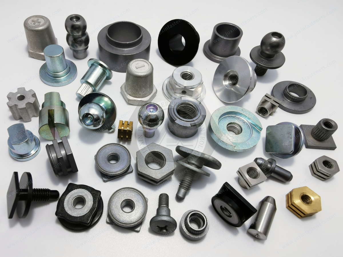
JUXIN FASTENERS OEM Fastening and CNC Sourcing Solutions
JUXIN FASTENERS supplies industrial fastening components and drawing-based custom hardware for international industrial customers.
Relevant product families include:
Blind Rivets
Blind Rivet Nuts
Round-Body Rivet Nuts
Half-Hex Rivet Nuts
Full-Hex Rivet Nuts
Open-End Rivet Nuts
Closed-End Rivet Nuts
High-Strength Bolts
Self-Clinching Fasteners
Weld Fasteners
Custom Threaded Components
Precision CNC-Machined Parts
Custom Shafts and Spacers
Technical inquiries may involve drawing evaluation, material selection, surface treatment, installation requirements, dimensional tolerances, samples, inspection and bulk procurement.
Product feasibility and documentation requirements are confirmed against the customer's actual specifications.
Frequently Asked Engineering Questions
Which coating is suitable for automotive fasteners exposed to road salt?
Zinc-nickel and zinc-flake systems may be evaluated for suitable steel fasteners. Selection depends on the environment, material, coating specification and joint requirements.
Does salt spray testing predict automotive service life?
Not directly. Laboratory exposure results must be interpreted within the specified test and acceptance criteria.
What is the difference between bulbed and peel-type blind rivets?
Bulbed rivets form an enlarged blind-side bearing region, while peel-type rivets form an expanded or divided blind-side structure. Actual performance depends on the product design.
Can closed-end rivet nuts guarantee IP67 sealing?
No. The complete enclosure must be tested against the specified ingress-protection requirements.
Are half-hex rivet nuts suitable for double-layer aluminum?
They may be suitable for selected designs, but the material stack, hole geometry, grip range, setting process and retention must be validated.
Can metric rivet nuts replace UNC or UNF rivet nuts?
Not directly. Different thread systems require separate engineering verification.
What tolerance should be used for a precision shaft?
The required tolerance depends on the function, mating fit, load, operating conditions and drawing.
Engineering Conclusion
Automotive and EV fastening reliability depends on the complete assembly.
Corrosion-resistant coatings must match the environment and installation process.
Blind rivets must match the substrate, grip range, hole geometry and load requirements.
Blind rivet nuts must be evaluated for installation deformation, retention, corrosion and sealing compatibility.
Precision CNC-machined shafts require function-specific tolerances, surface finishes and material controls.
For engineering teams, the priority is reliable joint and component design.
For manufacturing teams, the priority is repeatable installation and efficient production.
For procurement teams, the priority is accurate specifications, supplier qualification and consistent supply.
Reliable OEM sourcing begins with the complete engineering drawing, not simply the nominal component size.
Request an OEM Fastener or Precision CNC Component Quotation
JUXIN FASTENERS welcomes inquiries from automotive OEMs, Tier-1 and Tier-2 suppliers, EV battery equipment manufacturers,
industrial machinery builders, design engineers, manufacturing engineers, production managers and international procurement teams.
For blind rivets, EV enclosure rivet nuts, corrosion-resistant bolts or custom CNC-machined shafts, send the relevant engineering information for technical review and quotation.
Please include:
Engineering drawing or CAD model
Material requirements
Dimensions and tolerances
Thread specification where applicable
Surface treatment
Application and installation conditions
Quality requirements
Initial quantity and annual demand
Packaging and delivery requirements
Company: JUXIN FASTENERS
Website: https://www.juxinfasteners.com/
Email: info@juxinfasteners.com
Contact JUXIN FASTENERS for drawing-based OEM fastener sourcing, component selection, sample requirements and bulk quotation requests.
Contact Us
Tel.:
+86 020 8621 0320
+86 020 3121 6067
E-mail:
Technical Support:
Navigation
SEND INQUIREY



