
Call Us
+86 136 6007 9809
Call Us
+86 136 6007 9809

Jan. 10, 2024
In precision mechanical systems, a lock nut does much more than prevent a threaded connection from loosening.
For machine tool spindles, precision bearings, ball screws, rotating shafts and industrial motion systems,
the lock nut can directly influence axial positioning, bearing preload stability, rotational accuracy, vibration behavior and long-term equipment performance.
A conventional lock nut may provide sufficient retention for general machinery. Precision rotating assemblies, however, require tighter control of:
Thread accuracy
Nut-face geometry
Axial positioning
Locking-force distribution
Bearing preload stability
Shaft protection
Repeatability after maintenance
F Series Precision Lock Nuts are engineered for these demanding applications.
Unlike conventional prevailing-torque lock nuts, F Series designs use precision locking elements distributed around the nut body to secure the nut against
the mating shaft thread after the required axial position or bearing preload has been established.
JUXIN FASTENERS supplies F Series precision lock nuts, spindle lock nuts, bearing lock nuts,
ball screw lock nuts, precision shaft nuts and custom precision lock nuts for OEM machine builders, industrial equipment manufacturers and precision mechanical applications.
For engineers, the critical question is not simply:
“Will the nut stay tight?”
The more important question is:
“Can the nut lock securely without disturbing the precision position or preload already established in the assembly?”
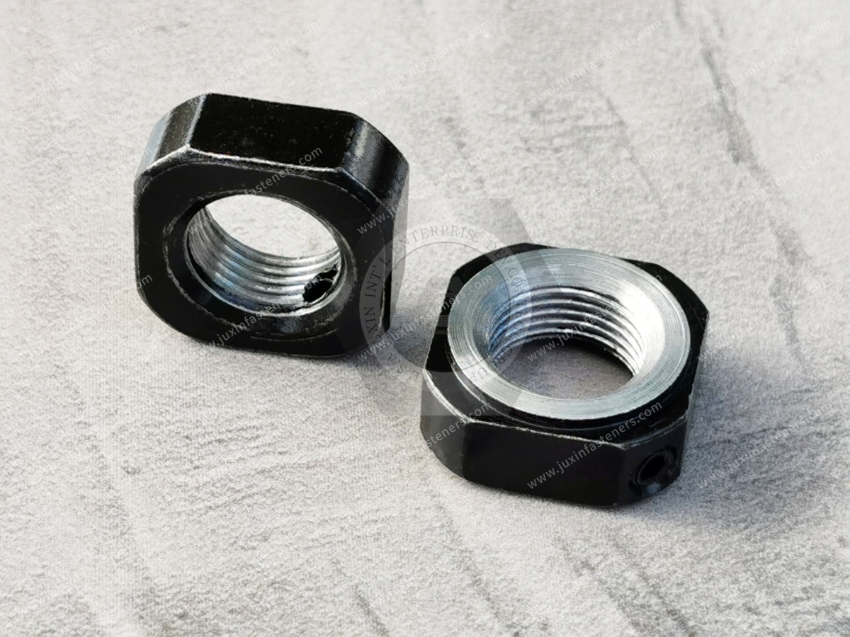
An F Series Precision Lock Nut is a precision-machined threaded nut designed for accurate axial positioning and secure retention of components mounted on threaded shafts.
Typical applications include:
CNC machine tool spindles
Ball screw support assemblies
Precision bearing systems
Grinding machines
Machining centers
Servo and drive systems
Precision rotating shafts
Industrial automation equipment
Mechanical transmission systems
The locking mechanism is fundamentally different from common nylon insert lock nuts or distorted-thread lock nuts.
In an F Series design, the main nut is first positioned on the shaft. Locking screws then act on precision locking elements arranged around the nut body.
These locking elements engage the mating shaft thread and create controlled resistance against unwanted rotation.
The result is an integrated precision positioning and mechanical locking system.
The F Series configuration uses multiple locking elements positioned around the circumference of the nut.
A typical design uses a three-point precision locking structure.
When the locking screws are tightened, they apply controlled pressure to the internal locking elements.
These elements contact the mating male thread and increase resistance against unwanted nut rotation.
The system therefore performs two different functions:
The main nut thread establishes axial position or bearing preload.
The locking elements secure that established position.
This distinction is important in precision machinery.
The locking screws should not be used to compensate for an incorrectly positioned nut.
The objective is to retain the correctly established axial position without unnecessarily disturbing the precision assembly.
The F Series configuration uses a 30° thread-side locking design.
When the locking screws apply pressure to the internal locking elements, the locking elements contact the mating shaft thread and generate controlled friction.
This design can provide:
Stable locking performance
Resistance to vibration-induced rotation
Controlled thread-side locking
Reduced risk of shaft-thread damage
No requirement for a separate lock washer in suitable assemblies
The locking elements in this configuration use phosphor bronze.
Using a suitable locking-element material helps create secure thread contact while reducing the risk of damaging the precision shaft compared with aggressive direct metal deformation methods.
For OEM projects, locking-element material, geometry and tightening requirements should always follow the approved product drawing.
The term “lock nut” covers products designed for very different engineering purposes.
| Engineering Requirement | Conventional Lock Nut | F Series Precision Lock Nut |
|---|---|---|
| Primary purpose | Prevent loosening | Precision positioning and retention |
| Typical application | General bolted joints | Spindles, bearings and ball screws |
| Locking principle | Nylon, deformation or friction | Precision thread-side locking |
| Axial positioning | General | High precision |
| Nut-face accuracy | General requirement | Critical assembly characteristic |
| Bearing preload application | Usually not primary | Common |
| Shaft protection | Application dependent | Important |
| Repeated adjustment | Limited or general | Suitable for precision maintenance |
| Lock washer | May be required | Often unnecessary |
| Typical users | General manufacturing | Machine tool and precision equipment OEMs |
A standard lock nut and a precision bearing lock nut may have the same nominal thread size but are not necessarily functionally interchangeable.
This is one of the most important differences between an ordinary nut and a precision lock nut.
In a precision bearing assembly, the nut face may act against:
A bearing inner ring
A precision spacer
A washer
Another accurately positioned mechanical component
If the functional face of the nut is not sufficiently controlled relative to the thread axis, tightening can introduce uneven axial loading.
Possible consequences include:
Uneven bearing preload
Increased runout
Bearing misalignment
Increased vibration
Higher operating temperature
Reduced bearing service life
Procurement teams therefore should not evaluate a precision lock nut using only:
Thread Size + Outside Diameter + Material
The relationship between the thread axis and functional bearing face is also an important engineering characteristic.
Depending on the manufacturing process and customer specification, F Series precision lock nuts can be produced using different thread-finishing methods.
Typical capabilities for the supplied configuration include:
Thread accuracy: ISO 4H
Precision face control: up to ≤0.002 mm, depending on the controlled specification
Thread accuracy: ISO 6H
Precision face control: up to ≤0.005 mm, depending on the controlled specification
These values should be treated as configuration-dependent manufacturing capabilities, not universal specifications for every precision lock nut.
Final requirements should be determined according to:
Customer drawing
Shaft design
Bearing arrangement
Required rotational accuracy
Operating speed
Preload requirement
Inspection specification
For general industrial fastening, normal commercial thread tolerances are often sufficient.
Precision shaft applications can require tighter thread control.
Tighter thread accuracy can help reduce unwanted positional variation between the nut and mating shaft.
However, engineers should not specify the tightest possible tolerance without considering the complete assembly.
Important factors include:
Mating shaft tolerance
Surface condition
Coating
Operating temperature
Assembly method
Required adjustability
Manufacturing capability
The correct solution is the tolerance combination that provides the required assembly performance.
A typical F Series configuration supplied by JUXIN FASTENERS uses 42CrMo4 alloy steel.
42CrMo4 provides a useful combination of:
Mechanical strength
Toughness
Fatigue resistance
Wear resistance
Machinability
A typical hardness range for this configuration is:
HRC 28–32
This provides a practical balance between strength, wear behavior and precision machining requirements.
For customized projects, material and heat-treatment requirements should follow the customer drawing and actual operating conditions.
For precision lock nuts, maximizing hardness is not necessarily the correct engineering objective.
Excessive hardness can affect:
Machinability
Thread finishing
Toughness
Heat-treatment distortion
Dimensional stability
Precision lock nut design requires a balance between:
Strength + Toughness + Wear Resistance + Dimensional Stability + Machinability
This becomes particularly important when tight thread and functional-face relationships must be maintained after manufacturing.
Bearing preload is one of the most important applications for precision shaft lock nuts.
Depending on the bearing arrangement, preload can influence:
Bearing stiffness
Rotational accuracy
System rigidity
Vibration
Heat generation
Bearing life
The precision lock nut helps establish and retain the required axial position.
However, the lock nut itself does not determine the correct preload.
Preload must be established according to the bearing manufacturer's technical requirements and the machine builder's assembly procedure.
The precision lock nut retains the engineered condition; it does not replace bearing-preload engineering.
Machine tool spindles operate under demanding combinations of:
High rotational speed
Cutting loads
Thermal variation
Bearing preload
Repeated acceleration and deceleration
Strict runout requirements
A precision spindle lock nut may be used to position and retain bearing components along the spindle shaft.
Typical equipment includes:
CNC machining centers
CNC lathes
Grinding machines
Milling machines
Precision boring equipment
High-speed spindle systems
For these applications, engineers should evaluate:
Thread accuracy
Nut-face accuracy
Shaft-thread tolerance
Bearing arrangement
Required preload
Rotational speed
Locking procedure
Ball screws are widely used where rotational motion must be converted into accurate linear movement.
Typical applications include:
CNC machine axes
Industrial robots
Automation equipment
Semiconductor equipment
Precision positioning systems
Measuring equipment
A ball screw support system often depends on accurately positioned bearings.
A ball screw lock nut helps retain the axial position established during bearing installation.
Important selection factors include:
Ball screw shaft thread
Bearing arrangement
Axial load
Required preload
Rotational speed
Positioning accuracy
Maintenance procedure
Precision bearings can be highly sensitive to installation conditions.
Improper axial positioning or uneven preload can affect:
Bearing temperature
Noise
Vibration
Runout
Friction
Service life
Precision bearing lock nuts are therefore used in suitable assemblies requiring controlled axial positioning.
Applications include:
Machine tool bearings
Precision motors
Industrial drive systems
High-speed rotating equipment
Automation systems
Grinding equipment often requires extremely stable spindle behavior.
Small deviations in bearing position or spindle runout can affect:
Surface finish
Dimensional accuracy
Grinding-wheel behavior
Machine vibration
For this reason, precision spindle lock nuts can be an important component of the spindle bearing system.
Modern automation systems increasingly require:
High positioning accuracy
Repeatable motion
Compact drive systems
Long maintenance intervals
Precision lock nuts may be used in:
Servo mechanisms
Linear-motion systems
Precision rotary axes
Robotic equipment
Automated production machinery
Where a threaded shaft locates a bearing or rotating component, the lock nut becomes part of the positioning system rather than simply a general fastener.
F Series precision lock nuts can be manufactured with:
Right-hand threads
Left-hand threads
Right-hand threads are commonly used in standard mechanical assemblies.
Left-hand threads may be required for specific shaft designs, rotating systems or equipment configurations.
When specifying thread direction, confirm:
Shaft drawing
Existing mating thread
Direction of rotation
Assembly direction
Maintenance procedure
Thread direction should always follow the engineered shaft design.
Precision lock nuts can use different locking arrangements depending on available installation space and shaft geometry.
Possible configurations include:
Radial locking designs
Axial locking designs
Compression locking arrangements
Application-specific locking-element layouts
Selection depends on:
Available radial space
Available axial space
Tool access
Shaft diameter
Bearing arrangement
Required locking force
Maintenance accessibility
For custom machinery, supplying the complete shaft or assembly drawing is more reliable than selecting a lock nut from thread size alone.
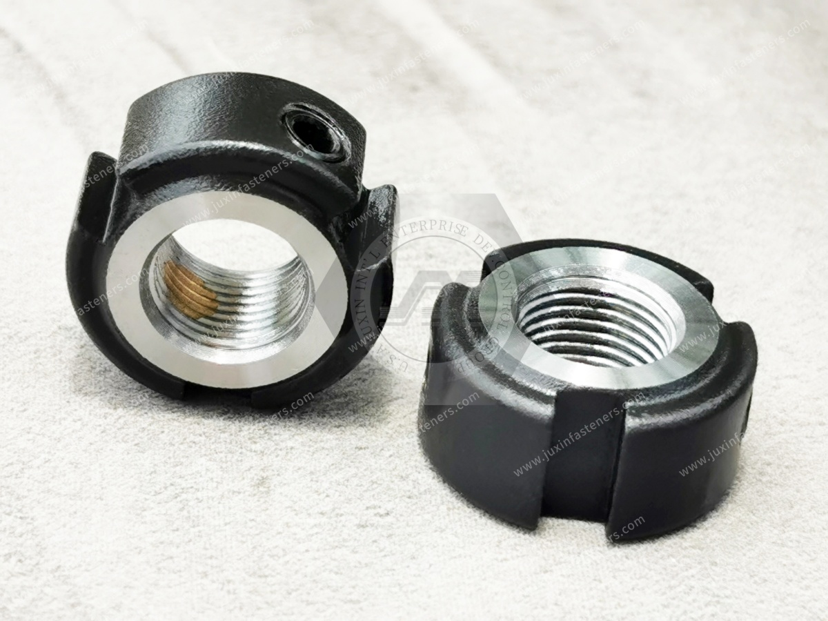
Correct installation is essential for maintaining positioning accuracy and locking performance.
Confirm:
Correct thread size
Correct pitch
Correct thread direction
Clean thread
No burrs
No visible damage
Check:
Main thread condition
Functional face
Locking screws
Locking elements
Surface condition
Part identification
Thread the nut carefully onto the shaft.
Do not force the nut onto a damaged or mismatched thread.
Position the nut according to the approved machine or bearing assembly procedure.
Depending on the application, engineers may need to verify:
Axial displacement
Bearing preload
Rotational resistance
Runout
Other equipment-specific parameters
After the correct position has been established, tighten the locking screws according to the specified procedure.
Where multiple locking screws are used, controlled and balanced tightening helps avoid uneven locking force.
Depending on the application, verify:
Nut position
Bearing preload
Axial runout
Rotational behavior
Locking condition
This is an important engineering distinction.
The main nut position establishes the axial condition.
The locking screws are intended to retain that position.
Using the locking screws to compensate for an incorrectly positioned nut can introduce uneven loading and reduce precision.
The correct sequence is:
Position → Establish Preload → Lock → Verify
Traditional shaft nut systems may use:
Tab washers
Locking plates
Shaft grooves
Other external locking components
An integrated precision locking system can eliminate some of these components in suitable designs.
Potential benefits include:
Fewer assembly components
No washer-tab bending
Reduced requirement for shaft locking grooves
Easier adjustment
Easier maintenance
Cleaner assembly design
The final machine design should determine whether any additional retaining feature is required.
Precision machinery often requires periodic maintenance.
Bearings, seals or other rotating components may eventually need replacement.
An integrated precision locking system can simplify servicing because the nut can be unlocked, removed and reinstalled without destroying a tab washer or similar sacrificial locking element.
Before reusing a precision lock nut, inspect:
Main thread
Functional face
Locking screws
Locking elements
Surface condition
Corrosion
Deformation
For critical machinery, reuse criteria should follow the equipment manufacturer's approved maintenance procedure.
A nut may begin threading onto a shaft but still have an incorrect pitch, tolerance or thread direction.
Never force installation.
Contamination and burrs can create abnormal resistance and compromise positioning accuracy.
Overtightening can damage:
Locking elements
Shaft threads
Locking screws
Nut body
Tightening one locking screw excessively before the others may create uneven locking-force distribution.
Even a correctly sized nut can affect bearing behavior if the functional face is not sufficiently controlled relative to the thread axis.
A high-quality precision lock nut cannot compensate for incorrectly established bearing preload.
A visually similar precision nut may not have the same:
Thread tolerance
Face accuracy
Locking geometry
Material
Hardness
Locking-element design
| Application | Primary Requirement | Important Selection Factors |
|---|---|---|
| Machine tool spindle | Runout and preload stability | Thread accuracy, face accuracy, locking stability |
| Ball screw support | Axial positioning | Thread fit, bearing preload, repeatability |
| Precision bearing | Controlled axial position | Face geometry, preload, shaft fit |
| Grinding spindle | Rotational accuracy | Runout, vibration, locking stability |
| Servo drive | Position repeatability | Shaft thread, locking design, serviceability |
| Automation system | Long-term positioning | Vibration, maintenance, repeatability |
| High-speed shaft | Stable retention | Material, locking system, assembly condition |
| Custom machinery | Drawing compliance | Dimensions, tolerance, material, inspection |
A procurement team may encounter several products described as “bearing nuts.”
They should not automatically be treated as equivalent.
A standard bearing nut may be sufficient where:
General axial retention is required
Precision requirements are moderate
A lock washer or external retaining system is acceptable
An F Series precision lock nut should be evaluated where:
Axial positioning accuracy is critical
Bearing preload must remain stable
Machine runout matters
Repeated adjustment is required
External locking components are undesirable
Precision machining is specified
In a precision rotating system, accuracy is not determined by one component.
The complete accuracy chain can include:
Shaft Thread → Nut Thread → Nut Functional Face → Spacer → Bearing → Housing → Preload → Locking System
If one interface is poorly controlled, final spindle or bearing performance can be affected.
This is why replacing a precision lock nut based only on nominal thread size can create problems.
Two nuts may have the same nominal thread and outside dimensions while having different functional precision.
These requirements are sometimes incorrectly treated as the same characteristic.
They are not.
Thread accuracy primarily controls how the nut interfaces with the shaft thread.
Functional-face accuracy influences how the nut loads the adjacent bearing, spacer or precision component.
A precision lock nut may therefore require control of both.
Specifying only a tight thread tolerance without controlling the functional face may not provide the expected assembly performance.
A sourcing description such as:
“M30 precision lock nut”
may be insufficient for an OEM project.
A complete RFQ should identify:
Product series or drawing
Thread size
Thread pitch
Thread direction
Thread tolerance
Nut dimensions
Functional-face accuracy requirement
Material
Hardness
Locking-element material
Number of locking points
Surface treatment
Required inspection
Quantity
Annual demand
For replacement projects, provide the existing approved drawing or sample whenever possible.
Second-source qualification requires more than dimensional similarity.
Engineering and supplier-development teams should compare:
Overall dimensions
Thread designation
Thread tolerance
Thread direction
Thread-to-face relationship
Functional-face accuracy
Material
Heat treatment
Hardness
Locking-screw design
Locking-element material
Locking geometry
Surface treatment
Installation requirements
Inspection method
Traceability requirements
For critical spindle or bearing applications, functional validation in the actual assembly may also be required.
Depending on the drawing and application, inspection can include:
Raw material verification
Dimensional inspection
GO/NO-GO thread inspection
Precision thread inspection
Functional-face inspection
Hardness testing
Locking-element inspection
Locking-screw inspection
Surface-condition inspection
Coating inspection
Visual inspection
Lot traceability
For precision applications, basic thread gauging alone may not provide enough information to validate the complete functional requirement.
Thread grinding can be considered when the application requires tighter thread accuracy than conventional precision turning can economically provide.
Typical applications can include:
High-precision spindle assemblies
Tight axial positioning systems
High-end machine tools
Critical bearing assemblies
However, thread grinding increases manufacturing complexity and cost.
It should therefore be specified because the application requires it, not simply because a ground thread appears more technically advanced.
For many industrial applications, a properly controlled precision-turned thread can provide adequate performance.
Design engineers searching for precision lock nuts often need answers to questions such as:
How does the locking system work?
Will locking affect bearing preload?
What thread tolerance is available?
What face accuracy can be controlled?
Can the nut be reused after maintenance?
Are left-hand threads available?
What material and hardness are used?
Procurement, sourcing and supplier-development teams are more likely to search for:
F Series precision lock nut manufacturer
Precision bearing lock nut supplier
Spindle lock nut manufacturer
Ball screw lock nut supplier
Custom precision lock nuts
OEM bearing lock nuts
Drawing-based precision lock nuts
Alternative precision lock nut supplier
A useful B2B technical page must support both search intents.
For faster engineering review and quotation, provide:
2D drawing
Existing part number or series
Thread diameter
Thread pitch
Right-hand or left-hand thread
Required thread tolerance
Outside diameter
Nut width
Functional-face accuracy requirement
Material
Hardness
Surface treatment
Locking-element requirement
Locking-screw requirement
Shaft material
Mating shaft thread tolerance
Bearing type
Application
Rotational speed where relevant
Preload requirement where available
Inspection requirements
Documentation requirements
Sample quantity
Production quantity
Estimated annual demand
Packaging requirements
For replacement or second-source projects, provide the currently approved drawing or physical sample where available.
It is a precision-machined shaft nut with integrated locking elements designed to retain an accurately established axial position in spindle,
bearing, ball screw and other precision mechanical assemblies.
No. Nylon insert lock nuts are primarily anti-loosening fasteners for conventional bolted joints.
F Series precision lock nuts are designed for accurate shaft positioning and precision mechanical assemblies.
Typical applications include CNC spindles, grinding machines, machining centers, precision bearings, ball screws, servo systems and rotating equipment.
The functional nut face may contact a bearing inner ring, spacer or other precision component. Face error can contribute to uneven loading or positioning error.
A typical JUXIN FASTENERS configuration uses 42CrMo4 alloy steel with a hardness of approximately HRC 28–32. Final requirements should follow the approved drawing.
They represent different internal-thread tolerance classes. The appropriate tolerance should be selected together with the mating shaft thread and required assembly accuracy.
Yes. Precision lock nuts can be manufactured with left-hand or right-hand threads according to the shaft design.
They may be suitable for repeated installation depending on condition and application. Threads, functional faces and locking components should be inspected before reuse.
No. The main nut position establishes the axial condition according to the bearing assembly procedure. The locking system retains the established position.
The integrated locking structure can eliminate the need for a separate lock washer in suitable designs. The complete assembly specification remains controlling.
Yes. Drawing-based production can support special dimensions, thread specifications, left-hand and right-hand threads,
material requirements and application-specific configurations subject to engineering review.
For stronger topical authority and internal SEO architecture, connect this page contextually to relevant existing JUXIN FASTENERS content:
Lock Nut Installation Guide
Lock Nuts and Anti-Loosening Nuts Selection Guide
High Strength Nuts and Bolt Compatibility
Industrial Nut Types and Selection Guide
CNC Machined Fasteners and Custom Precision Components
Fastener Solutions for Industrial Machinery
Custom Nuts and Special Nuts Made to Drawing
Use the existing indexed JUXIN FASTENERS URLs when implementing these internal links. Do not create duplicate URLs simply for internal linking.
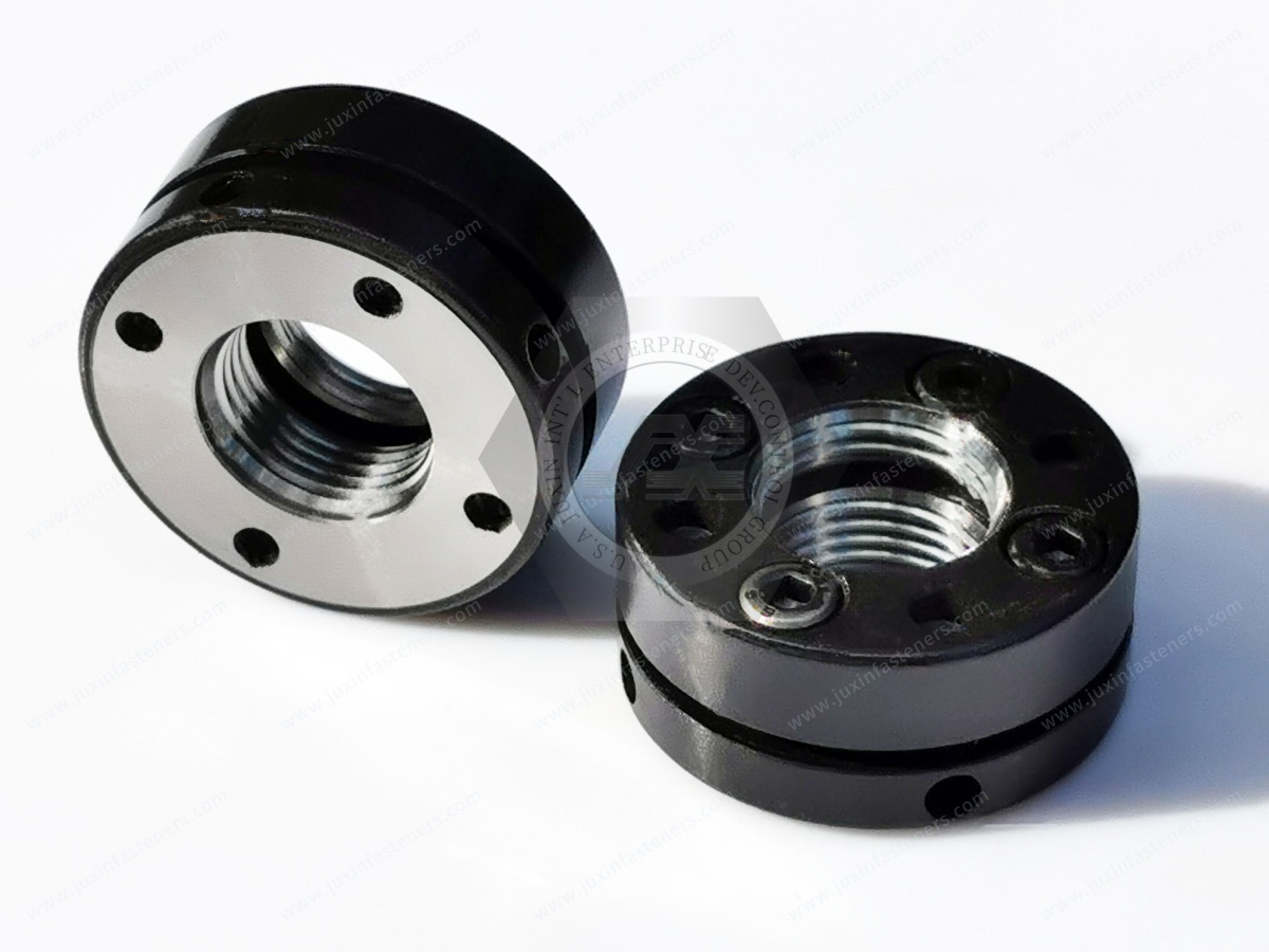
JUXIN FASTENERS supports OEM and industrial customers requiring precision lock nuts and drawing-based fastening components for machinery and precision mechanical assemblies.
Our capabilities for suitable projects include:
Precision CNC machining
Precision turning
Thread grinding
Metric thread production
Left-hand and right-hand threads
Special dimensions
42CrMo4 alloy steel configurations
Drawing-based custom production
Dimensional inspection
Thread inspection
Hardness verification
OEM project support
For design engineers and mechanical engineers, send the shaft drawing, bearing arrangement, thread specification, required positioning accuracy, preload information and operating conditions.
For procurement managers, strategic sourcing and supplier-development teams, send the controlled drawing, material, hardness,
inspection requirements, sample quantity, annual demand and documentation requirements.
For second-source qualification, send the existing approved drawing or specification so the comparison can include functional precision characteristics rather than only nominal thread dimensions.
The correct precision lock nut should be selected as part of the complete mechanical positioning system:
Shaft Thread + Nut Thread + Functional Face + Bearing/Spacer + Preload + Locking System + Inspection Control
That is the difference between sourcing an ordinary threaded nut and sourcing a precision mechanical positioning component.
For new designs, replacement projects or second-source qualification, send your 2D drawing, thread specification,
required accuracy, material, hardness, application, quantity and annual demand to JUXIN FASTENERS.
Our engineering team can review the application and support standard or customized precision lock nut requirements.
Email: info@juxinfasteners.com
Website: www.juxinfasteners.com
 MORE NEWS
Oct. 13, 2026
Contact Us
Tel.:
+86 020 8621 0320
+86 020 3121 6067
E-mail:
Technical Support:
Navigation
SEND INQUIREY