
Call Us
+86 136 6007 9809
Call Us
+86 136 6007 9809

Sep. 27, 2026
Fir tree fasteners and nylon barbed panel clips provide a fast, lightweight method for mounting panels, trim, insulation,
wiring harnesses, cables, tubing, protective covers, and other non-structural components to sheet metal, molded plastic, and other suitable substrates.
Their distinctive shank geometry uses multiple flexible fins, ribs,
or barbs that deflect as the fastener enters a mounting hole and then resist withdrawal through mechanical interference with the hole wall and surrounding panel geometry.
This fastening principle makes fir tree fasteners particularly useful for high-volume OEM assembly where rapid push-in installation, one-sided access,
low component weight, electrical isolation, and resistance to loosening under vibration may be required.
Applications extend across automotive and electric vehicles, commercial vehicles, electrical equipment, appliances,
HVAC systems, industrial automation, telecommunications, data-center equipment, agricultural machinery, outdoor power equipment, industrial enclosures, and many other engineered assemblies.
However, reliable fir tree retention depends on much more than matching a nominal shank diameter.
The functional fastening system includes:
fastener geometry + fin geometry + mounting-hole diameter and tolerance + panel thickness + substrate stiffness + polymer condition
+ installation force + service load + temperature + moisture + vibration + removal requirements
Juxin Fasteners supplies standard and custom plastic fir tree fasteners, nylon barbed clips, panel retainers, cable and harness mounting clips,
and related plastic fastening components for industrial OEM applications. Engineering and procurement teams can provide an existing part number,
physical sample, 2D drawing, 3D model, or application dimensions for cross-reference evaluation, sample development, and second-source sourcing.
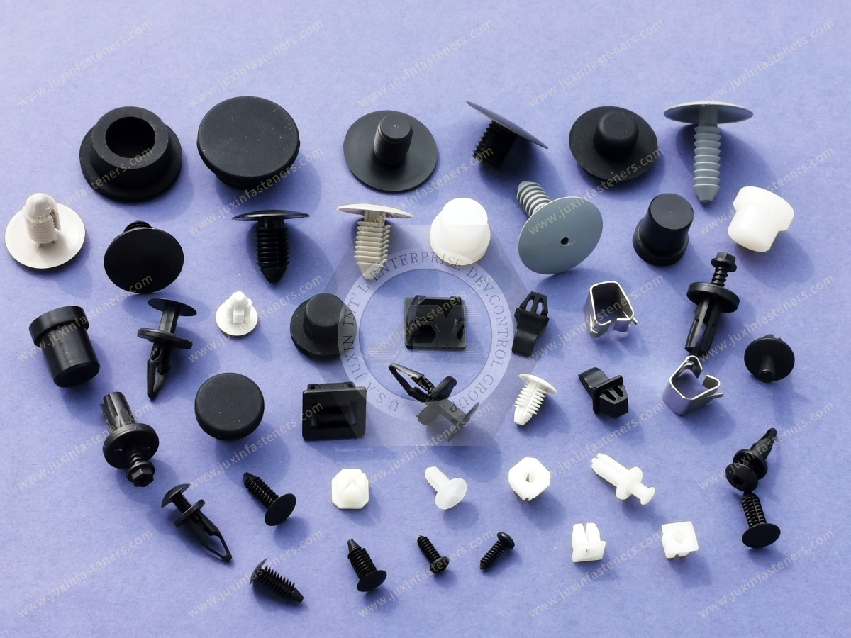
A fir tree fastener is a push-in plastic fastener with multiple flexible retaining fins or barbs arranged along its shank.
The profile resembles the layered branches of a fir tree, which gives the fastener its common industrial name.
During installation, the flexible features deform as the shank enters the mounting hole.
After insertion, the fins attempt to recover toward their molded position and create interference against the hole wall and surrounding panel interface.
Retention can result from a combination of:
Radial interference
Flexible-fin recovery
Friction
Barb geometry
Engagement with the hole edge
Local mechanical undercut
Progressive engagement of multiple fins
Because several fins can participate in the retention mechanism, fir tree fasteners may accommodate a useful range of installation conditions depending on the individual design.
That does not mean that every fir tree fastener will fit any panel thickness or hole size. Each design has a defined dimensional operating window that must be matched to the mating assembly.
Industrial catalogs sometimes group fir tree clips, arrowhead clips, Christmas-tree fasteners, barbed push fasteners, and push-in panel clips into similar product families.
For engineering purposes, these terms should not automatically be treated as interchangeable.
Fir tree fasteners normally use multiple flexible fins or ribs distributed along the insertion shank.
The multiple engagement features can provide progressive interference during installation.
Arrowhead-style fasteners typically use one or more larger flexible locking features shaped to compress through the mounting hole and expand after insertion.
Their locking behavior can therefore differ substantially from a multi-fin fir tree shank.
Barbed push fastener is a broader description covering various products that use molded barbs or ribs to resist withdrawal.
A fir tree fastener can be considered a type of barbed push-in fastener, but not every barbed push fastener is necessarily a fir tree design.
Plastic push rivets frequently use an expandable body, center pin, or another activation mechanism.
This differs from a conventional fir tree fastener, which normally obtains retention directly from its molded flexible shank features during insertion.
These distinctions matter during cross-reference sourcing. A replacement component should be evaluated by its actual geometry and retention mechanism rather than by a broad catalog name alone.
Standard fir tree fasteners combine a head with a multi-fin shank.
They can be used for attaching:
Plastic panels
Trim components
Insulation
Covers
Lightweight sheet materials
Protective layers
Interior components
The head distributes contact over the retained component while the shank engages the mounting hole.
Head diameter, head profile, shank length, fin diameter, fin spacing, and mounting-hole compatibility are all important selection variables.
Harness-mount fir tree clips integrate a fir tree mounting feature with a separate cable or harness retention geometry.
The upper section may incorporate:
Cable saddle
Wire clip
Harness channel
Cable-tie mounting feature
Bundle retainer
Routing clip
This allows a single component to perform two functions:
mounting to the host structure + positioning the cable or harness
These clips are widely relevant to automotive electrical systems, EV wiring, appliances, electrical equipment, industrial machinery,
telecommunications systems, and other assemblies containing organized cable routes.
A fir tree mounting shank can also be integrated with a cable-tie base.
The fir tree section anchors the mount to the panel, while a separate cable tie secures the wire bundle, hose, or other routed component.
This architecture can provide more flexibility than an integrated fixed-diameter cable clip because the cable tie can accommodate different bundle diameters.
Specialized head geometries can support:
Fluid lines
Small tubes
Pneumatic lines
Drain lines
Washer-fluid lines
Low-load hoses
For these applications, both sides of the component require engineering review:
fir tree-to-panel interface + clip-to-tube interface
A correct mounting shank does not guarantee correct tube retention if the clip diameter or material flexibility is unsuitable.
Some assemblies combine a fir tree mounting feature with a panel, trim, edge, or insulation-retention head.
These products can simplify assembly by eliminating separate clips and mounting hardware.
It is tempting to describe a fir tree fastener as simply "locking behind the panel," but this does not accurately describe every design.
Many fir tree fasteners derive retention progressively from multiple flexible fins interacting with the mounting hole.
Depending on the design, the fins can:
Compress during insertion
Deflect backward
Generate radial interference
Engage the edge of the hole
Resist reverse movement through their orientation
Share withdrawal load across several engagement points
Some designs may engage significantly with the rear edge of a panel. Others obtain much of their retention through interference along the hole or panel thickness.
For this reason, the assumption that the final fin must always pass completely beyond the rear panel surface is not universally applicable.
The actual retention mechanism should be determined from the fastener geometry.
Fir tree fasteners depend strongly on the relationship between fin diameter and mounting-hole diameter.
If the mounting hole is oversized, the fins may not deflect or engage sufficiently.
Possible consequences include:
Reduced pull-out retention
Fastener movement
Panel rattle
Clip rotation
Inconsistent assembly
Premature release under vibration
If the mounting hole is undersized, the fins may experience excessive deformation.
Possible consequences include:
High insertion force
Fin damage
Shank deformation
Panel damage
Difficult manual assembly
Excessive automated installation load
Incomplete seating
The correct hole size should therefore come from the actual product specification, validated drawing, or approved assembly test rather than from a generic rule for all fir tree clips.
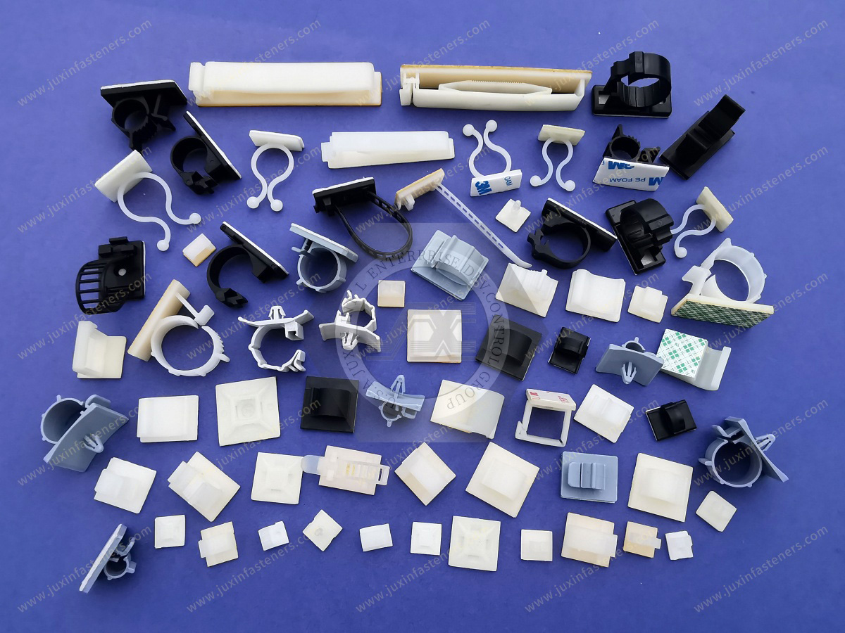
A nominal mounting-hole diameter alone does not fully define the interface.
Production variation can arise from:
Punching
Drilling
Laser cutting
Mold shrinkage
Tool wear
Coating buildup
Burr formation
Sheet-metal distortion
Molded-hole draft
Engineers should evaluate the fastener across the expected minimum and maximum production hole conditions.
A fastener that performs well at nominal diameter but becomes difficult to install at the minimum hole tolerance or loses retention at the maximum tolerance may not provide a robust production solution.
Not every mounting hole is round.
Certain panel assemblies use:
Round holes
Oval holes
Slotted holes
Rectangular openings
Keyed features
The retention and anti-rotation behavior of the fastener can change significantly with hole geometry.
A fir tree fastener intended for a round hole should not automatically be specified for a slot merely because the nominal width appears compatible.
Where positional tolerance requires a slot, the fastener design should be evaluated specifically for that interface.
Panel thickness affects how many retaining features interact with the mounting interface and where those features are positioned relative to the front and rear surfaces.
Unlike some two-piece rivets with a more clearly defined expansion zone, a multi-fin fir tree fastener can achieve retention through several possible engagement points.
The correct panel-thickness range therefore depends on the individual fin spacing, shank length, hole geometry, and head position.
For assemblies containing multiple layers, engineers should evaluate the complete stack-up.
Potential layers can include:
Sheet metal
Plastic panel
Trim
Insulation
Foam
Coating
Gasket
Adhesive layer
The actual compressed assembly condition may be more important than simply adding nominal material thicknesses.
A common sourcing mistake is assuming that a fir tree clip suitable for the correct hole diameter will automatically suit the panel thickness.
These are separate variables.
Hole diameter controls radial fin interference and insertion behavior.
Panel thickness affects which fins engage, where the head seats, and how the fastener interacts with the complete assembly.
A cross-reference fastener can therefore have the correct nominal shank size and still perform differently because its fin spacing or active shank geometry is not appropriate for the panel.
Punched sheet metal can introduce:
Burrs
Edge rollover
Local deformation
Non-round holes
Coating accumulation
Sharp burrs can cut or permanently damage polymer fins during insertion.
The direction of punching can also influence the interface encountered by the fastener.
Where retention consistency is important, testing should use production-representative holes rather than ideal laboratory holes.
A molded plastic mounting boss or hole behaves differently from sheet metal.
Important variables can include:
Wall thickness
Local stiffness
Hole draft
Mold shrinkage
Material flexibility
Rib reinforcement
Temperature
Long-term creep of the host material
If both the fastener and host structure are polymeric, long-term behavior should consider deformation in both components rather than evaluating only the clip.
Polyamide 66 is widely used for plastic clips and fasteners because appropriate grades can provide a useful balance of:
Strength
Toughness
Flexibility
Fatigue resistance
Wear resistance
Moldability
These characteristics can support the repeated elastic deformation required when flexible fins pass through a mounting hole.
However, "PA66" alone is not a complete engineering material specification.
Available formulations can include:
Unfilled grades
Impact-modified grades
Heat-stabilized grades
UV-stabilized grades
Flame-retardant grades
Reinforced formulations
Other application-specific compounds
The correct formulation depends on the actual service environment and fastener geometry.
Automotive, power-electronics, industrial machinery, appliance, and HVAC applications may expose clips to elevated temperatures.
Heat-stabilized PA66 or another suitable engineering polymer may be considered where standard material performance is insufficient.
However, the term "heat stabilized" should not be interpreted as one universal service-temperature rating.
Long-term suitability depends on:
Specific resin grade
Exposure temperature
Exposure duration
Mechanical stress
Moisture
Chemical environment
Fastener geometry
Material selection should therefore be based on project conditions and documented resin performance.
Impact-modified materials may be evaluated for applications involving:
Mechanical shock
Installation impact
Low-temperature handling
Vehicle vibration
Outdoor equipment
Improved toughness can reduce the risk of brittle fin damage, but material modification can also influence stiffness and dimensional behavior.
Because fin stiffness affects insertion and retention, material changes should be evaluated at finished-fastener level.
Polyamides absorb moisture from their environment.
Moisture can change:
Stiffness
Toughness
Dimensions
Fin flexibility
Insertion force
Retention behavior
Electrical properties
Dry-as-molded nylon can therefore behave differently from environmentally conditioned material.
For fir tree fasteners this is especially relevant because the flexible fins are active mechanical elements.
If a fin becomes more flexible, installation force may decrease while the retention response can also change.
Engineering teams should therefore understand whether validation samples represent:
Dry production condition
Conditioned material
Actual expected service condition
For demanding applications, environmental conditioning can be incorporated into validation.
Plastic fasteners can experience time-dependent deformation under sustained stress.
For a fir tree clip, this matters when retention relies heavily on continuously deflected fins pressing against the mounting-hole wall.
Long-term behavior can be affected by:
Polymer grade
Fin geometry
Degree of deflection
Temperature
Moisture
Service time
Host-panel material
This creates an important engineering distinction.
A clip that shows high initial pull-out force immediately after installation does not automatically guarantee identical retention after extended service at elevated temperature or humidity.
Where long-term retention is critical, qualification should consider the actual environmental and loading conditions.
Fir tree fastener design requires a balance between two competing objectives:
easy installation + secure retention
Large or stiff fins can increase interference and potentially increase retention, but they can also increase insertion force and risk damaging the fastener or panel.
Very flexible or lightly interfering fins can make installation easy but may not provide sufficient retention for the application.
Important variables include:
Fin outside diameter
Fin thickness
Fin angle
Fin spacing
Shank diameter
Polymer modulus
Hole diameter
Panel thickness
Hole edge condition
The best design is not necessarily the fastener with the highest possible pull-out force.
It is the fastener that provides the required retention while remaining compatible with the assembly process and host structure.
Manual assembly places importance on:
Operator insertion effort
Ergonomics
Seating feedback
Fastener orientation
Assembly speed
Automated installation adds additional requirements such as:
Consistent feeding
Orientation control
Stable insertion force
Repeatable seating depth
Dimensional consistency
Detection of incomplete installation
If a project will transition from prototype manual assembly to automated production, that future installation process should be considered during fastener selection.
Fir tree fasteners are commonly used in applications exposed to vibration, particularly vehicles, appliances,
HVAC equipment, machinery, telecommunications equipment, and outdoor power equipment.
Flexible polymer fins can maintain engagement without threaded loosening mechanisms, but vibration resistance is not an automatic property of every fir tree fastener.
Dynamic performance depends on:
Fastener geometry
Hole fit
Panel stiffness
Retained component mass
Load direction
Temperature
Moisture
Aging
Vibration spectrum
A clip that performs well in one mounting orientation may behave differently if service loads act directly in the extraction direction.
Application testing should therefore reproduce the actual load path whenever retention is important.
For a fir tree wiring-harness clip, engineers must validate two independent functional interfaces.
Evaluate:
Mounting-hole size
Hole tolerance
Panel thickness
Insertion force
Pull-out retention
Rotation
Vibration
Evaluate:
Cable diameter
Bundle diameter
Tube outside diameter
Retention force
Local compression
Abrasion risk
Routing direction
Minimum bend requirements
Installation and service access
A clip can have excellent panel retention and still be unsuitable if the cable-retention geometry damages or inadequately supports the harness.
This dual-interface analysis is particularly important in automotive, EV, electrical equipment, robotics, and industrial automation applications.
Plastic mounting clips can avoid introducing a metallic conductive path between components.
This can be useful in:
Electrical enclosures
Power electronics
Battery equipment
Telecommunications hardware
Electronic assemblies
Control cabinets
They can also avoid direct metallic contact with painted or coated panels.
However, a plastic fastener does not independently guarantee electrical safety or eliminate all galvanic-corrosion mechanisms.
Electrical isolation, creepage, clearance, grounding, corrosion, and environmental protection must be evaluated at system level.
Plastic fasteners may encounter:
Automotive fluids
Oils
Greases
Detergents
Cleaning agents
Coolants
Fuels
Industrial chemicals
Chemical compatibility depends on the specific polymer grade, concentration, temperature, exposure time, and mechanical stress.
For chemically demanding environments, material compatibility should be reviewed using the actual exposure conditions rather than assuming that all nylon clips provide identical resistance.
Agricultural machinery, outdoor power equipment, transportation systems, HVAC installations, solar-related equipment, and other outdoor assemblies can expose plastic fasteners to UV radiation and weathering.
Where outdoor life is important, an appropriate UV-stabilized polymer may be considered.
The term "UV stabilized" should not be converted into a universal outdoor service-life claim. Actual performance depends on formulation, exposure intensity, temperature, environment, and application geometry.
The orientation of fir tree fins is specifically designed to resist withdrawal.
This means removal force can be substantially different from insertion force.
Depending on the fastener and panel, removal can:
Permanently deform fins
Damage the mounting hole
Scratch coatings
Break the fastener
Reduce retention during reinstallation
If regular service access is required, engineers should determine whether a removable push rivet, reusable panel fastener, threaded fastener, or another fastening architecture is more appropriate.
A component that can physically be pulled out should not automatically be classified as reusable.
Possible causes include:
Hole too small
Excessive fin interference
Sharp burrs
Incorrect material condition
Low temperature
Wrong fastener geometry
Possible causes include:
Oversized hole
Insufficient fin engagement
Incorrect shank geometry
Unsuitable panel thickness
Damaged fins
Excessive host-panel flexibility
Possible causes include:
Sharp panel edges
Undersized holes
Excessive installation force
Brittle material condition
Chemical degradation
Incorrect polymer selection
Possible causes can include:
Round fastener geometry where anti-rotation is required
Oversized mounting hole
Inadequate interference
Torque applied by the retained harness or tube
Potential contributors include:
Polymer creep
Stress relaxation
Temperature
Moisture
Host-panel deformation
Vibration
Environmental aging
Failure analysis should examine the complete assembly rather than assuming the clip itself is the only variable.
Fir tree fasteners are particularly common in vehicle assemblies because they support fast installation and can integrate directly with trim, wiring, hose, and panel-retention features.
Potential applications include:
Wiring harnesses
Interior trim
Door assemblies
Instrument panels
Trunk liners
Wheel-arch components
Underbody covers
Insulation
Acoustic materials
Small hoses and tubes
Electrical cable routing
EV applications can additionally involve:
Battery-system auxiliary wiring
High- and low-voltage harness routing
Electronic control equipment
Thermal-management routing
Charging-system related assemblies
Fasteners used near electrical systems should be selected according to the complete mechanical, thermal, electrical, and environmental requirements of the vehicle.
Trucks, buses, specialty vehicles, and rail equipment can expose clips to extended vibration, large temperature variations, maintenance cycles, and demanding service environments.
Applications can include:
Wiring
Interior panels
Insulation
Covers
Tubing
Equipment enclosures
Retention requirements should reflect actual vehicle duty rather than simply transferring a clip specification from a lighter-duty application.
Fir tree fasteners can support:
Cable routing
Internal covers
Lightweight panels
Wire bundles
Insulation
Protective components
Where the clip is used inside electrical equipment, the exact polymer grade and applicable equipment requirements should be considered.

High-density servers, telecommunications cabinets, network equipment, and related infrastructure require extensive cable and wire management.
Fir tree mounting clips can be relevant for:
Cable routing
Wire-bundle retention
Internal panel attachment
Airflow-management components
Equipment enclosures
Material requirements can include temperature, flammability, electrical characteristics, and serviceability depending on the application.
HVAC equipment can use fir tree clips for:
Wiring harnesses
Sensor cables
Insulation
Lightweight covers
Control-system wiring
Tubing and drainage-related components
Temperature cycling, condensation, vibration, and cleaning environments should be considered during material and fastener selection.
Industrial machinery and robotics contain extensive electrical, sensor, pneumatic, and control-system routing.
Fir tree clips may support:
Sensor cables
Control wiring
Pneumatic tubing
Protective covers
Cable bundles
For moving equipment, dynamic cable motion and repeated flexing should be evaluated separately from the panel-mount retention of the clip.
Potential applications include:
Internal wiring
Insulation
Control housings
Covers
Tubing
Lightweight panels
Where elevated temperatures, cleaning chemicals, moisture, or food-service cleaning cycles are present, material selection should reflect those conditions.
Agricultural machinery, lawnmowers, battery-powered outdoor equipment, and other outdoor machines can expose clips to:
UV
Moisture
Mud
Oils
Fuel
Vibration
Temperature cycling
Material selection and retention validation should reproduce the intended service environment where practical.
Fir tree fasteners are strong candidates when the assembly requires:
Rapid push-in installation
One-sided access
No tightening torque
Lightweight fastening
Electrical isolation
Cable or harness mounting
Non-structural panel retention
Vibration-tolerant retention when properly validated
A different fastener may be preferable where the application requires:
Use an appropriate threaded or structural fastening system rather than relying on a plastic push clip.
Consider reusable panel fasteners, captive screws, threaded fasteners, or other service-oriented systems.
A two-piece plastic push rivet may be more suitable.
Use dedicated PCB spacers, standoffs, or board supports.
A bushing or grommet may be more appropriate than a mounting clip.
A dedicated clamp, P-clip, or engineered harness-retention system may provide better load distribution.
Choosing the fastening architecture first prevents engineers from optimizing the wrong product type.
A practical fir tree fastener selection process begins with the assembly rather than the catalog.
Identify:
Hole diameter
Hole tolerance
Hole shape
Panel material
Panel thickness
Coating
Burr condition
Rear clearance
Identify whether the fastener retains:
Panel
Trim
Insulation
Cable
Wire bundle
Hose
Tube
Cover
For cable and tube clips, specify the bundle or outside diameter.
Consider:
Installation force
Pull-out retention
Lateral load
Rotation
Vibration
Shock
Component mass
Specify:
Temperature
Humidity
Water exposure
UV
Chemicals
Oils
Cleaning agents
Determine:
Permanent installation
Occasional removal
Required reuse
Maintenance access
Final approval should use representative production panels and environmental conditions where performance is critical.
Procurement teams frequently need a second source for an existing plastic clip.
Useful starting information includes:
Existing supplier part number
Physical sample
2D drawing
3D model
Assembly drawing
Application photographs
Mounting-hole dimensions
A cross-reference should compare more than appearance.
Important characteristics include:
Head geometry
Shank length
Fin outside diameter
Fin thickness
Fin spacing
Core diameter
Mounting-hole requirement
Panel thickness
Material
Color
Installation force
Pull-out behavior
Removal behavior
Two fir tree clips can look almost identical while providing significantly different insertion and retention characteristics.
A physical sample is extremely useful for dimensional and geometric comparison.
However, visual inspection alone generally cannot establish:
Exact polymer grade
Heat stabilization
UV stabilization
Impact modification
Flame-retardant formulation
Original material conditioning
Customer-specific compliance requirements
For second-source development, unknown material requirements should be confirmed through available drawings,
specifications, material documentation, or customer requirements rather than guessed from appearance.
Standard components can be suitable where existing geometry matches the assembly requirements.
Custom development may be considered when the application requires:
Special head geometry
Custom fin diameter
Modified fin spacing
Unique shank length
Integrated cable clip
Integrated tube clip
Cable-tie mounting feature
Anti-rotation geometry
Special color
Application-specific polymer
Customer-specific dimensions
Custom geometry should be reviewed as a complete mechanical system because changing one fin dimension can alter insertion and retention behavior.
For a new design or second-source qualification, physical samples should be tested in representative hardware.
Depending on the application, validation may consider:
Dimensional fit
Installation force
Seating
Pull-out retention
Rotation
Vibration
Removal behavior
Reinstallation where applicable
Temperature conditioning
Humidity conditioning
Chemical exposure
Cable or tube retention
Testing requirements and acceptance criteria should follow the OEM's actual application requirements.
For efficient technical review, provide as much of the following information as possible:
Product type
Existing part number
Existing supplier reference
2D drawing
3D CAD model
Physical sample
Mounting-hole diameter and tolerance
Hole shape
Panel thickness
Panel material
Coating
Required head style
Shank length
Required material
Color
Cable bundle diameter, if applicable
Tube outside diameter, if applicable
Required insertion behavior
Required retention performance
Service temperature
Moisture exposure
Chemical exposure
UV exposure
Vibration requirements
Removal and reuse requirements
Required documentation
Sample quantity
Order quantity
Estimated annual volume
Packaging requirements
Qualification schedule
The more complete the assembly information, the more accurately a standard or custom solution can be evaluated.
Depending on the customer's industry and supplier-development requirements, requested documentation may include:
Product drawings
Material information
Material datasheets
Dimensional inspection reports
RoHS declarations
REACH declarations
Lot traceability
Sample approval records
Customer-specific quality documentation
Documentation requirements should be defined during RFQ and qualification rather than assumed for every plastic component.
For an existing component:
Existing Part Number or Sample → Geometry Review → Mounting Interface Review → Material Requirement Review
→ Candidate Cross-Reference → Sample Evaluation → Assembly Validation → Second-Source Approval → Production RFQ
For a new application:
Assembly Requirement → Hole and Panel Definition → Load and Environment Review → Fastener Architecture Selection
→ Material Selection → Sample → Validation → Production Approval → RFQ
For a custom component:
Application Requirement → 2D/3D Drawing or Sample → Geometry and Material Review → Custom Development Evaluation → Samples → Assembly Testing → Qualification → Production RFQ
This process helps prevent a common sourcing problem: approving a fastener because it looks similar before confirming that it performs correctly in the production assembly.
Juxin Fasteners supports engineering, procurement, supplier-development, and supply-chain teams sourcing standard and custom plastic fastening components, including:
Fir tree fasteners
Nylon fir tree clips
Barbed push fasteners
Plastic panel retainers
Wiring harness clips
Cable mounting clips
Cable-tie mounts
Tube and hose clips
Plastic push rivets
Nylon panel fasteners
Cable-management hardware
Plastic bushings and grommets
Other custom plastic fastening components
For standard sourcing, provide the required dimensions, mounting-hole information, material, quantity, and application.
For cross-reference and second-source projects, send the existing part number, drawing, physical sample, or available assembly data.
For custom components, provide the 2D/3D engineering information and functional requirements available for the application.
Juxin Fasteners can review the requirement and support the next stage of dimensional evaluation, sample confirmation, second-source qualification, or production RFQ development.
Email: info@juxinfasteners.com
Website: www.juxinfasteners.com
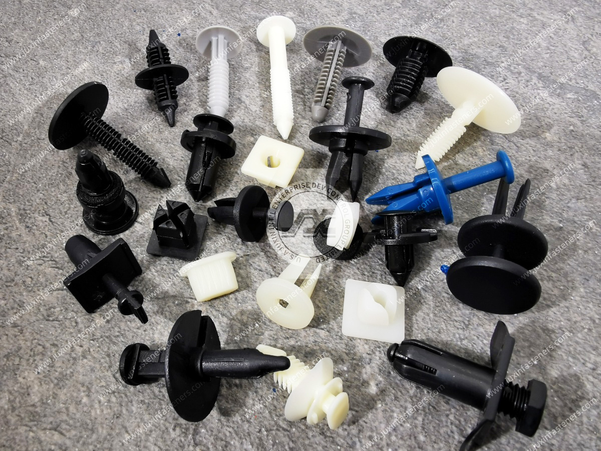
Previous: Nylon Screws, Nuts & Washers
 MORE NEWS

Sep. 27, 2026

Sep. 27, 2026

Sep. 27, 2026
Contact Us
Tel.:
+86 020 8621 0320
+86 020 3121 6067
E-mail:
Technical Support:
Navigation
SEND INQUIREY