
Call Us
+86 136 6007 9809
Call Us
+86 136 6007 9809

Oct. 30, 2023
Stainless steel helical thread inserts, also called wire thread inserts, helical inserts or wire inserts,
are precision-formed wire components installed into specially prepared tapped holes to create a durable internal thread.
They are widely used for two different engineering purposes:
Thread reinforcement in new components
Repair of damaged internal threads
Helical inserts are especially useful when designers need a threaded connection in materials where the parent thread may be vulnerable to stripping, wear or repeated assembly.
Typical parent materials can include:
Aluminum alloys
Magnesium alloys
Cast materials
Selected steels
Certain engineered materials where the insert system has been validated
However, a helical insert should not be selected simply because the parent material is “soft.”
The correct design depends on the parent material, thread size, insert length, available wall thickness, hole depth,
applied load, assembly frequency, installation process and service environment.
For OEM sourcing, these variables should be defined before selecting the insert.
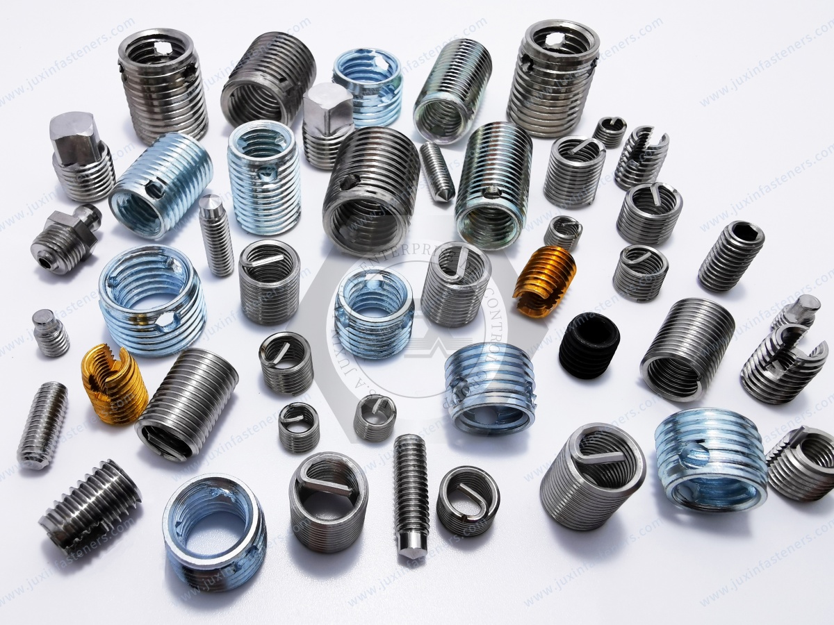
A helical thread insert is manufactured from wire formed into a precisely controlled helical shape.
The installed insert creates an internal thread for the mating screw or bolt while its external wire form engages with the specially prepared parent-material thread.
Unlike a solid threaded bushing, a wire thread insert has a relatively thin-wall installation envelope.
This makes it useful where engineers want to reinforce or repair a thread without introducing the larger outside diameter associated with some solid insert systems.
Common terminology includes:
Helical thread insert
Wire thread insert
Wire insert
Screw thread insert
Stainless steel thread insert
Thread repair insert
Some markets also use trademark-derived terminology when referring generally to this technology. For engineering drawings and RFQs,
however, it is preferable to specify the actual insert type and technical requirements rather than relying only on a brand-associated name.
The insert is installed into a specially prepared receiving thread in the parent material.
Its free outside diameter is designed to create radial engagement after installation.
During installation, the insert is driven into the prepared hole. Once positioned correctly, the insert establishes a threaded interface between the parent component and the mating screw.
The resulting load path becomes:
bolt or screw → insert → parent material
rather than:
bolt or screw → directly tapped parent material
This changes how thread loads are transferred into the component.
The actual performance depends on the complete assembly geometry and should be validated for critical applications.
Helical inserts are not only repair components.
Design engineers can specify them from the beginning of a product design when the threaded joint requires characteristics that may be difficult to obtain from a directly tapped parent material.
Potential reasons include:
Repeated assembly and disassembly
Thread reinforcement in lightweight materials
Reduced wear of the parent thread
Serviceability
Controlled replacement strategy
Weight-sensitive designs
Maintaining a specified internal thread in a relatively compact installation envelope
This can be particularly relevant when aluminum or magnesium components are used to reduce system weight.
Internal threads can be damaged through:
Cross-threading
Overloading
Incorrect fastener installation
Repeated assembly
Wear
Corrosion
Improper torque
Parent-material damage
Replacing an entire housing, casting or machined component because of one damaged threaded hole can be expensive.
Where sufficient parent material remains and the insert system is suitable, a helical thread insert can provide a repair strategy.
The damaged hole is typically reworked to accept the insert-specific receiving thread, after which the insert is installed to restore the required nominal internal thread.
However, thread repair should not be treated as universally acceptable.
For safety-critical or highly loaded components, the repair method should follow the applicable engineering or maintenance requirements.
These are related but different search intents.
The insert is included in the original design.
The engineer can optimize:
Boss diameter
Hole depth
Insert length
Parent material
Installation access
Assembly process
The component already exists and the original thread has been damaged.
The engineer must evaluate:
Remaining material
Existing hole condition
Available repair diameter
Hole depth
Structural integrity
Original thread
Application criticality
Do not assume that every stripped thread can simply be drilled larger and fitted with an insert.
A free-running helical insert provides an internal thread intended to allow normal mating screw movement according to the specified thread system.
This type is commonly considered for:
Thread reinforcement
Thread repair
Repeated assembly
General industrial applications
It should not be described as an automatic anti-loosening device.
If vibration resistance or prevailing torque is required, the joint should be engineered accordingly.
A screw-locking or locking helical insert incorporates a locking feature intended to interact with the mating screw.
Depending on the specific insert design, this can provide prevailing torque characteristics.
Potential applications include assemblies exposed to:
Vibration
Repeated dynamic loading
Equipment movement
Controlled retention requirements
However:
locking insert ≠ universally vibration-proof joint
Joint performance still depends on:
Mating fastener
Thread geometry
Insert specification
Installation
Joint preload
External loading
Temperature
Number of reuse cycles
Customer requirements
Critical applications should be validated under actual service conditions.
A useful selection path is:
The main objective is thread reinforcement
The main objective is thread repair
Normal screw installation behavior is required
Another locking strategy is already used
Prevailing torque is specifically required
The design specification calls for a locking insert
Vibration or dynamic conditions justify additional retention
The mating screw and reuse requirements are compatible
Do not substitute one type for the other without engineering review.
Traditional helical inserts may include a tang used by the installation tool to drive the insert.
After installation, the tang may need to be removed depending on:
Hole type
Assembly design
Application
Insert specification
Tang removal creates an additional manufacturing operation.
The process should consider:
Tang access
Tang collection
Inspection
Risk of residual fragments
Blind-hole geometry
Production volume
This becomes especially important in cleanliness-controlled equipment.
Tangless inserts use an installation design that does not require a conventional break-off tang.
Potential manufacturing advantages can include:
Elimination of tang break-off
Reduced concern about loose tang fragments
Simplified installation workflow in appropriate applications
Better suitability for some automated assembly processes
However, tangless and tang-type inserts are not automatically interchangeable.
Installation tooling, insert geometry and qualification requirements may differ.
When comparing the two technologies, ask:
Is the hole through or blind?
Is loose-particle control important?
Is the assembly cleanliness-sensitive?
Will installation be manual or automated?
Is high-volume production planned?
What tooling is available?
Does the customer specification define the insert type?
For semiconductor, electronics, medical or other cleanliness-sensitive equipment, the manufacturing process can be as important as the insert itself.
The old concept of a “particle-free insert” requires careful engineering language.
A stainless steel helical insert by itself does not make an assembly particle-free.
Particle control depends on the complete process, including:
Drilling
Tapping
Cleaning
Insert installation
Tang removal where applicable
Final inspection
Assembly environment
Tangless designs may reduce one potential source of loose fragments, but cleanliness must still be controlled through the complete manufacturing process.
Aluminum is one of the most common parent materials associated with helical thread inserts.
Typical applications can include:
Housings
Gearboxes
Equipment frames
Automotive components
Electronic equipment
Thermal-management equipment
Industrial machinery
Lightweight structures
A helical insert can move the threaded interface from a directly tapped aluminum thread to a stainless steel insert system.
But performance still depends on the aluminum alloy and geometry.
Important variables include:
Parent-material strength
Boss diameter
Edge distance
Hole depth
Insert length
Applied load
Mating fastener
Installation quality
Helical insert length is commonly expressed relative to the nominal thread diameter.
For example:
M6 × 1 × 1.5D
can indicate:
M6 nominal internal thread
1 mm pitch
Insert length based on approximately 1.5 times the nominal diameter
However, engineers should follow the specific manufacturer's or drawing convention because notation can vary.
Longer is not automatically stronger.
The required insert length depends on:
Parent material
Available hole depth
Required load transfer
Boss geometry
Screw engagement
Insert design
Excessive length can create installation or packaging problems without providing useful additional performance.
Helical inserts can be produced for different thread systems.
Depending on the application, these may include:
ISO metric threads
Unified inch threads
Other drawing-defined thread forms
An insert does not automatically “convert” a metric threaded hole to an inch thread or vice versa.
Such a conversion requires a properly designed receiving hole and insert system.
Never force an insert intended for one thread system into a differently prepared hole.
One of the most important engineering points is that a helical insert does not normally install into an ordinary tapped hole of the same nominal size.
The parent component requires an insert-specific receiving thread.
The general process is:
prepare hole → tap insert receiving thread → clean → install insert → position correctly → remove tang if required → inspect
The exact process depends on the insert design and application.
For a new design, the hole should be machined according to the insert-system requirements.
For a repair application, the damaged thread must first be evaluated.
The engineer should confirm:
Existing hole diameter
Damage condition
Remaining wall thickness
Hole depth
Through-hole or blind-hole condition
Nearby features
Do not simply select the next available drill size without reference to the required insert system.
Helical inserts normally require an insert-specific tap rather than the ordinary tap used to create the final internal thread directly in the parent material.
The tapping operation must control:
Thread geometry
Alignment
Hole depth
Chip removal
Parent-material condition
Poor tapping can create installation problems even when the insert itself is dimensionally correct.
Machining debris should be removed before installation.
This is especially important for:
Blind holes
Hydraulic equipment
Electrical equipment
Semiconductor equipment
Precision machinery
Cleanliness-controlled assemblies
Residual chips can interfere with insert seating and later assembly.
The insert is installed using tooling compatible with its design.
Installation should control:
Orientation
Depth
Thread alignment
Coil condition
Tool engagement
Do not force an insert that does not advance correctly.
Excessive installation force can indicate:
Incorrect receiving thread
Damaged insert
Misalignment
Contamination
Incorrect tooling
For a tang-type insert, tang removal depends on the specific installation system and application.
If removal is required, the process should ensure that the tang does not remain where it could interfere with:
Mating fastener installation
Moving components
Electrical equipment
Fluid systems
Cleanliness requirements
Blind holes require particular attention because fragment retrieval may be more difficult.
After installation, inspect the completed threaded interface according to the drawing or process requirements.
Potential checks include:
Insert depth
Insert position
Internal thread condition
Tang removal where required
Cleanliness
Mating screw installation
Critical applications may require additional customer-defined validation.
A useful engineering article should explain failure mechanisms rather than describing inserts only as “stronger threads.”
Common problems can originate from:
If the hole or tap geometry is incorrect, the insert may not seat properly.
A correctly installed insert cannot compensate for inadequate wall thickness or a weak surrounding boss.
Too little engagement may not provide the required load transfer.
Excessive length can create installation interference.
The insert does not eliminate poor screw alignment.
An incorrectly positioned insert can interfere with assembly.
Tool geometry must match the insert design.
Improper tang removal or uncontrolled fragments can create manufacturing issues.
Stainless steel inserts installed into a dissimilar parent material may require galvanic-corrosion evaluation depending on the environment.
This is particularly important in aluminum assemblies.
A stainless steel insert and aluminum parent material create a dissimilar-metal interface.
Whether galvanic corrosion becomes significant depends on:
Electrolyte exposure
Environment
Relative surface areas
Aluminum alloy
Stainless grade
Protective finishes
Joint design
Do not assume that stainless steel automatically improves the corrosion performance of the complete assembly.
For wet, marine or chemically exposed equipment, the material interface should be evaluated.
Installing a helical insert changes the threaded interface.
Engineers should not automatically assume that a torque value developed for a directly tapped parent material remains valid.
Torque requirements depend on:
Mating screw
Thread system
Lubrication
Insert type
Parent component
Bearing surface
Required preload
For critical joints, use the assembly specification rather than a universal torque chart.
Both technologies create an internal threaded interface, but their structures differ.
May be preferred when:
A relatively compact installation envelope is important
Thread reinforcement is needed
Thread repair is required
Low component mass is valuable
May be preferred when the design requires characteristics associated with a solid-body insert architecture.
Selection depends on:
Parent material
Load path
Wall thickness
Installation process
Service requirements
Available space
Neither technology is universally superior.
These technologies should not be confused.
A helical insert installed into a specially tapped receiving thread is different from common threaded inserts engineered specifically for thermoplastics.
Plastic insert technologies may include:
Heat-installed inserts
Ultrasonic-installed inserts
Mold-in inserts
Press-in designs
For thermoplastic components, engineers should evaluate the insert technology specifically designed for the polymer, boss geometry and installation method.
Do not automatically use a metal-thread repair solution as a plastic-insert solution.
A rivet nut is another completely different fastening technology.
Typically requires a prepared hole and insert receiving thread in the parent material.
Creates a threaded attachment in sheet or thin-section material through mechanical deformation and can often be installed from one side.
Use rivet nuts when the assembly architecture requires a blind-installed threaded attachment in suitable sheet material.
Use helical inserts when the design requires reinforcement or repair of a threaded hole in a suitable parent component.
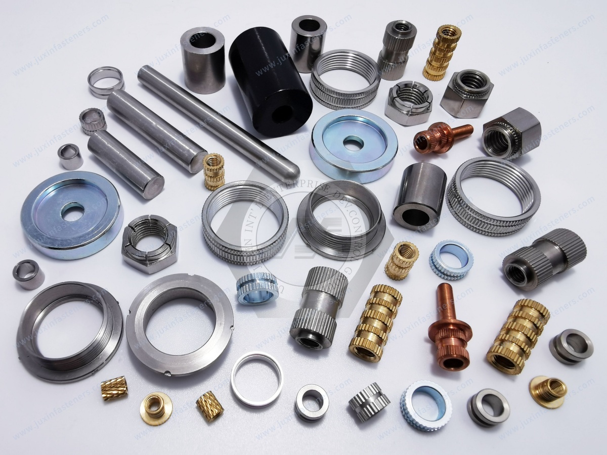
Self-clinching fasteners are installed into appropriately prepared sheet material through controlled pressing.
They rely on material displacement and mechanical retention around the clinching feature.
They are not interchangeable with helical inserts.
A useful technology decision path is:
machined/cast component requiring reinforced thread → consider threaded insert technology
thin sheet requiring permanent pressed-in thread → consider self-clinching fastener
thin sheet with one-sided installation → consider rivet nut
The final selection depends on material, geometry, access and load requirements.
Helical inserts may be used in automotive and transportation equipment for applications involving:
Aluminum housings
Machinery components
Repairable threaded interfaces
Repeatedly serviced assemblies
Lightweight structures
For production automotive applications, the insert must be specified as part of the complete drawing-controlled assembly.
Relevant factors include:
Parent material
Thread size
Insert type
Insert length
Installation process
Torque requirement
Corrosion environment
Production volume
Industrial machinery is a strong application area for thread reinforcement and repair.
Potential components include:
Machine housings
Pumps
Gearboxes
Fixtures
Tooling
Automation equipment
Maintenance components
A damaged thread in a large machined component can be expensive to replace.
Where engineering approval permits, an insert-based repair can provide a controlled restoration method.
Semiconductor and precision equipment can place additional emphasis on:
Cleanliness
Particle control
Precision installation
Material compatibility
Serviceability
Tangless insert systems may be considered where eliminating the tang-break operation is beneficial.
However, the entire drilling, tapping, cleaning and installation process must still meet the equipment's cleanliness requirements.
Helical inserts may also be used in:
Electrical enclosures
Equipment housings
Power electronics
Data center infrastructure
UPS equipment
Thermal-management components
They can be useful where equipment requires repeatable threaded service connections in aluminum or other suitable parent materials.
Electrical grounding or conductivity requirements should be evaluated separately from mechanical thread performance.
Helical thread inserts have established applications in aerospace-related threaded assemblies and repair systems.
However, aerospace and MRO work requires strict control of:
Approved materials
Insert specifications
Installation procedures
Repair manuals
Traceability
Inspection
JUXIN FASTENERS should not substitute a general industrial insert into an aerospace-controlled application unless the customer's applicable drawing, specification and qualification requirements are satisfied.
A practical engineering selection path is:
parent material → nominal thread → load requirement → hole geometry → available wall thickness → insert type → insert length → tang/tangless → installation process → environment → validation
This is more reliable than selecting an insert from thread size alone.
Two inserts described as “M6 stainless steel wire inserts” are not automatically equivalent.
Compare:
Thread system
Thread pitch
Insert length
Free-running or locking type
Tang or tangless design
Material specification
Surface/lubrication requirement
Installation-system compatibility
Customer specification
Packaging
Inspection requirements
Annual volume
For existing OEM components, the approved drawing should remain the primary technical reference.
For second-source development, begin with:
existing drawing → approved insert/sample → receiving hole → installation tooling → mating screw → assembly requirements → validation
Important comparisons include:
Nominal thread
Pitch
Length
Coil geometry
Installation features
Free-running
Locking
Tang
Tangless
Confirm the specified stainless steel or other required material rather than accepting a generic “stainless” description.
Confirm compatibility with:
Receiving thread
Installation tool
Hole depth
Tang-removal process where applicable
Validate with the actual:
Parent component
Mating screw
Installation process
Service requirement
A visually similar wire insert should not automatically be approved as a second source.
For an existing part, provide:
Drawing
Nominal thread size
Thread pitch
Insert length
Free-running or locking type
Tang or tangless design
Material requirement
Existing sample where available
Quantity
Annual demand
For a new design, provide:
Parent material
Required internal thread
Hole type: through or blind
Available hole depth
Available boss diameter or wall thickness
Mating screw
Expected loading
Assembly frequency
Environment
Installation method
Production volume
For thread repair, provide:
Original thread size
Parent material
Damaged-hole condition
Hole depth
Surrounding geometry
Component function
Application criticality
Required quantity
For second-source qualification, provide:
Current drawing
Approved physical sample
Existing insert specification
Receiving-hole details
Installation tooling information
Mating fastener
Current validation requirements
Annual demand
Related engineering and sourcing resources include:
Threaded Inserts
Threaded Inserts for Aluminum
Threaded Inserts for Plastic
Self-Clinching Fasteners
Rivet Nuts
Stainless Steel Fasteners
CNC Machined Components
Automotive Fasteners
Custom Fasteners
Fastener Material Selection
These technologies solve different fastening problems and should be selected according to the parent material, access, geometry and assembly requirements.
JUXIN FASTENERS supports standard and custom industrial fastening components for global OEM and industrial sourcing projects.
Relevant product capabilities include:
Helical thread inserts
Threaded inserts
Rivet nuts
Self-clinching fasteners
Stainless steel fasteners
Automotive fasteners
CNC machined components
Drawing-controlled custom fasteners
Projects can begin from:
Customer drawing
Existing specification
Physical sample
Thread requirement
Parent-material information
Existing component
Second-source requirement
For production and second-source programs, drawings and approved samples help establish the technical baseline before quotation and validation.
For design engineers:
parent material → thread requirement → joint load → geometry → insert type → installation → mating fastener → environment → validation
For procurement and supplier-development teams:
drawing/sample → thread specification → insert type → material → installation interface → annual volume → supplier comparison → qualification
The key principle is simple:
Do not source a helical insert by thread size alone.
Its performance depends on the insert, receiving hole, parent material, mating fastener and installation process working together as one threaded system.
For stainless steel helical thread inserts, wire thread inserts, free-running inserts, locking inserts, tang-type inserts, tangless inserts or other threaded insert requirements,
send JUXIN FASTENERS your technical information.
For an existing product, provide the drawing, insert specification and approved sample where available.
For a new design, provide the parent material, required thread, hole geometry, insert type, mating screw, application conditions, quantity and annual demand.
For second-source development, provide the existing drawing, approved sample, receiving-hole requirements, installation method, mating fastener and annual volume.
Email: info@juxinfasteners.com
Website: www.juxinfasteners.com
 MORE NEWS

Sep. 27, 2026

Sep. 27, 2026

Sep. 27, 2026
Contact Us
Tel.:
+86 020 8621 0320
+86 020 3121 6067
E-mail:
Technical Support:
Navigation
SEND INQUIREY