
Call Us
+86 136 6007 9809
Call Us
+86 136 6007 9809

Oct. 30, 2023
Self-tapping threaded inserts are solid threaded bushings designed to create a durable female thread in suitable parent materials while cutting or forming their own external engagement during installation.
They are commonly considered for applications involving aluminum alloys, magnesium alloys, cast materials and other materials compatible with the selected insert design.
Unlike helical wire inserts, many self-tapping threaded inserts do not require an insert-specific pre-tapped receiving thread.
Instead, the component is provided with a correctly sized installation hole, and the external cutting geometry of the insert establishes its engagement with the parent material during installation.
This distinction can simplify production while providing engineers with a replaceable metal internal thread for repeated assembly.
However, successful application depends on much more than selecting the internal thread size.
The engineering decision should consider:
parent material → internal thread → insert geometry → installation-hole diameter → available wall thickness → installation torque → loading → environment → validation
For procurement teams, a reliable sourcing specification should also define the drawing, material, dimensions, surface condition, production quantity and annual demand.
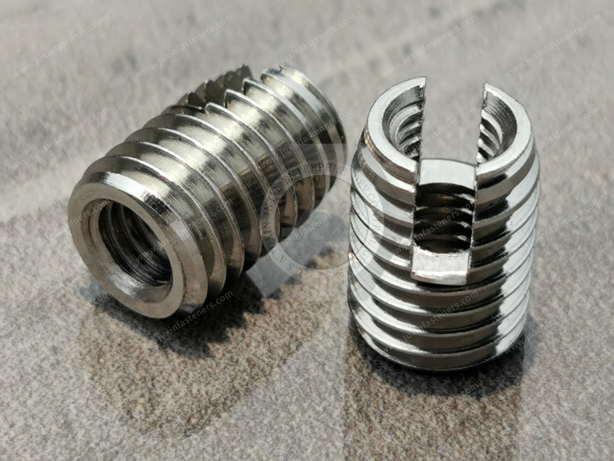
A self-tapping threaded insert is a solid insert incorporating:
An internal machine thread
An external thread or anchoring geometry
Cutting slots, cutting holes or another installation feature depending on design
Optional flange depending on the insert type
During installation, the insert is driven into a correctly prepared hole.
Its cutting features interact with the parent material to create the external engagement required to retain the insert.
The result is a metal internal thread that can accept the specified mating screw or bolt.
These components are also described in the market as:
Self-tapping inserts
Self-tapping bushings
Threaded bushings
Solid threaded inserts
Thread repair inserts
Threaded inserts for aluminum
Threaded inserts for soft metals
For engineering drawings and RFQs, the actual insert geometry and dimensions should be specified rather than relying on terminology alone.
A directly tapped thread can be suitable for many assemblies.
However, engineers may consider an insert when the parent material, service conditions or assembly requirements make a reinforced threaded interface desirable.
Typical reasons include:
Repeated assembly and disassembly
Reinforcement of threads in lower-strength parent materials
Repair of damaged internal threads
Increased serviceability
Reduced wear of the parent component
Replacement of a damaged insert rather than an entire component
Installation after casting or machining operations
Creation of a defined metal thread interface
The insert should be considered as part of the entire joint rather than as an isolated fastener.
The installation concept differs from a conventional internally and externally threaded bushing that requires a pre-tapped external receiving thread.
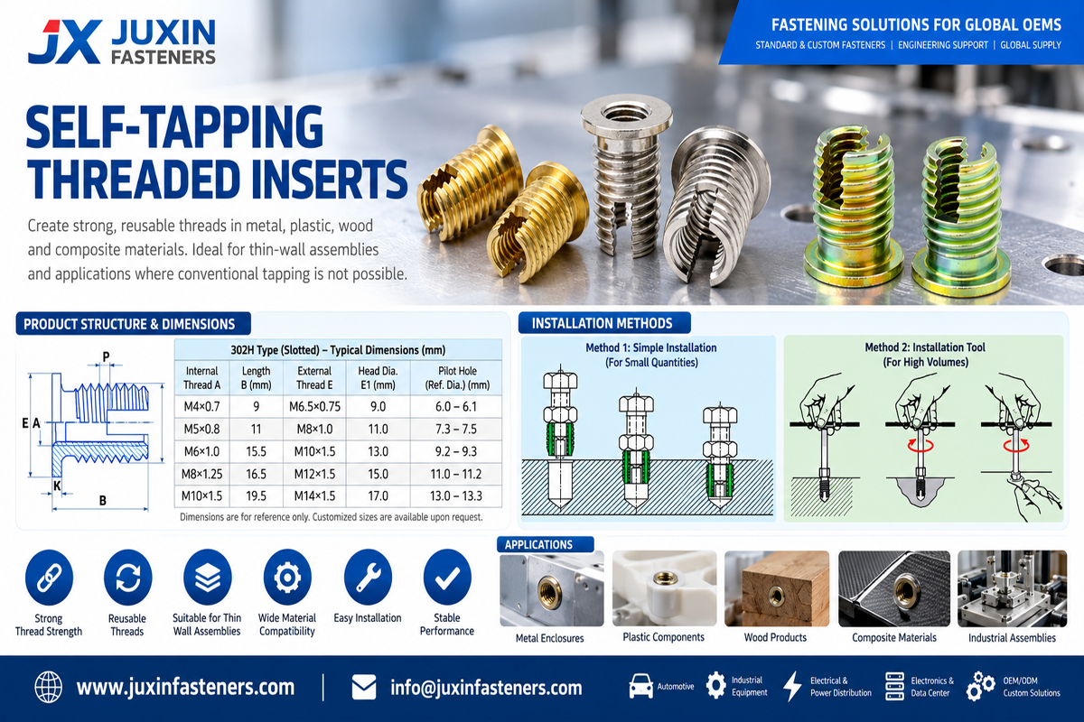
A typical self-tapping installation sequence is:
prepare hole → clean hole → align insert → drive insert → reach specified depth → inspect → assemble mating fastener
During installation, cutting slots or cutting holes at the insert exterior interact with the parent material.
This creates the external engagement required to anchor the insert.
The final load path becomes:
mating screw → insert → external insert interface → parent material
The strength of that system depends on both the insert and the material surrounding it.
A high-strength insert installed into an inadequately designed boss does not automatically produce a high-strength joint.
This distinction is important for both Google search relevance and engineering selection.
A self-tapping threaded insert and a helical wire thread insert are different technologies.
Typically:
Solid-body construction
Internal machine thread
External cutting/anchoring geometry
Installed into a prepared hole
May eliminate a separate receiving-thread tapping operation depending on the insert system
Typically:
Formed from precision wire
Helical construction
Installed into a specially prepared insert receiving thread
Requires the corresponding hole preparation and tapping process
Neither design is universally better.
The correct technology depends on:
Parent material
Component geometry
Available installation diameter
Load requirements
Production process
Repair requirements
Installation tooling
Service conditions
For more detail, see our Helical Thread Inserts for Thread Reinforcement and Repair engineering guide.
Aluminum components are a major application area for self-tapping threaded inserts.
Potential applications include:
Automotive housings
Gearboxes
Pump housings
Electrical enclosures
Power electronics
Thermal-management components
Industrial automation equipment
Robotics
Machine frames
Data center equipment
However, “aluminum” alone is not enough information for insert selection.
Different aluminum alloys can have significantly different mechanical and machining characteristics.
Engineers should evaluate:
Aluminum alloy
Material condition
Boss diameter
Wall thickness
Edge distance
Hole diameter
Hole depth
Insert length
Applied tensile load
Applied torque
Assembly frequency
The installation-hole recommendation should therefore be matched to the actual insert and parent material.
Depending on the insert geometry and validated application, self-tapping inserts may also be considered for suitable:
Magnesium alloys
Zinc alloys
Cast iron
Brass
Bronze
Other machinable parent materials
Do not assume one installation-hole diameter or one insert geometry will work identically across these materials.
A hole suitable for one aluminum alloy may not produce the same installation behavior in cast iron or another parent material.
Material-specific validation is therefore important.
Some self-tapping insert designs can be used with certain polymers, thermosets or composite materials, but this should not be generalized.
Thermoplastics have different failure mechanisms from metals, including:
Creep
Stress relaxation
Temperature-dependent behavior
Moisture sensitivity for certain polymers
Boss cracking
Local material displacement
For thermoplastic applications, engineers should also compare technologies specifically developed for plastic, such as:
Heat-installed threaded inserts
Ultrasonic threaded inserts
Mold-in inserts
Press-in inserts
Application-specific self-tapping inserts
A self-tapping insert intended for aluminum should not automatically be specified for plastic.
See our Threaded Inserts for Plastic guide for polymer-specific selection.
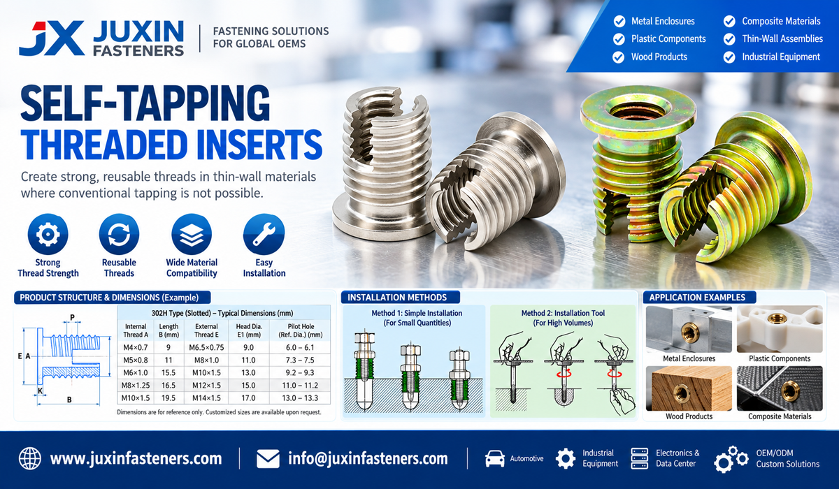
One common self-tapping insert architecture uses one or more cutting slots.
These slots provide cutting edges that interact with the parent material during installation.
This design may be suitable for a broad range of industrial applications depending on:
Parent material
Insert dimensions
Installation-hole diameter
Required load
Available boss geometry
The exact geometry should be selected from the drawing or validated insert specification.
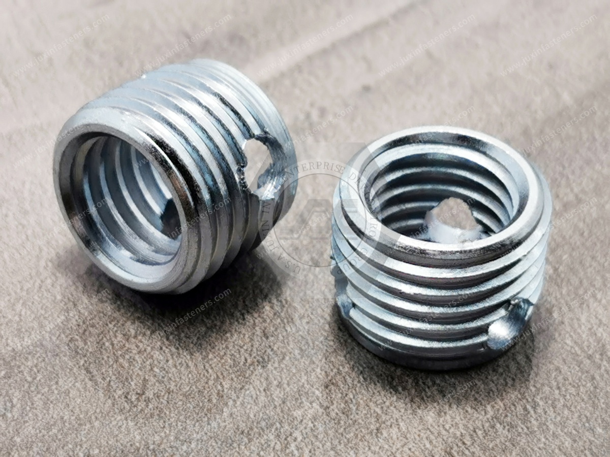
Another architecture uses cutting holes rather than open longitudinal slots.
The cutting edges created around these openings interact with the parent material as the insert is installed.
Depending on design, this architecture can provide different cutting behavior and wall geometry from slot-type inserts.
The choice between cutting-hole and cutting-slot designs should therefore be based on the actual parent material and installation requirement rather than visual preference.
Thin-wall inserts can be useful when the component provides limited radial space.
Potential reasons for considering a thin-wall design include:
Compact bosses
Limited wall thickness
Existing component geometry
Repair applications with restricted space
Lightweight component design
However, reducing insert wall thickness also changes the mechanical architecture.
Engineers should verify:
External diameter
Internal thread
Parent-material thickness
Installation torque
Pull-out requirement
Torque-out requirement
Thin-wall should be treated as a geometry option, not automatically as a lower- or higher-performance design.
A flanged insert incorporates a head or flange at one end.
Depending on the application, the flange can provide:
Defined installation stop
Increased bearing area
Axial positioning
Assembly orientation control
But a flange also changes packaging space and seating requirements.
The engineer should check:
Available counterbore or surface area
Interference with mating components
Required installation depth
Head clearance
Load direction
A flanged version should not automatically replace a non-flanged insert without checking the component geometry.
Hole geometry influences insert selection and installation.
A through hole can provide additional space for:
Cutting debris
Tool clearance
Insert runout
A blind hole requires closer attention to:
Bottom clearance
Chip accumulation
Insert length
Installation depth
Tool engagement
When cutting debris must not pass beyond the installation area, an insert geometry designed for the relevant chip-management requirement may be appropriate.
However, an insert should not be described as universally “chip-free.”
Chip behavior depends on:
Parent material
Cutting geometry
Hole preparation
Installation method
Cleaning process
Self-tapping threaded inserts can provide an effective repair method for damaged internal threads when the surrounding component remains structurally suitable.
A typical repair may involve:
Evaluating the damaged thread
Machining the hole to the specified installation diameter
Cleaning the hole
Installing the self-tapping insert
Inspecting the new internal thread
Validating the repaired assembly
Potential repair applications include:
Machine housings
Gearboxes
Fixtures
Automotive components
Industrial equipment
Maintenance assemblies
However, the insert does not restore damaged parent material outside the repair zone.
If cracking, severe deformation or structural damage exists around the hole, engineering evaluation is required before repair.
One of the most important parameters in self-tapping insert design is the installation-hole diameter.
If the hole is too small, possible problems include:
Excessive installation torque
Parent-material cracking
Insert deformation
Installation-tool overload
If the hole is too large, possible problems include:
Reduced external engagement
Lower retention
Insert movement
Reduced torque resistance
There is no universal hole-size rule that applies to every self-tapping insert.
The correct hole depends on:
Insert external geometry
Parent material
Insert size
Hole depth
Application requirements
This is why the parent material should always appear on an RFQ.
Design engineers sometimes focus on the insert while overlooking the surrounding component.
The parent material must provide enough structure around the insert to carry the resulting load.
Important geometry includes:
Boss outside diameter
Distance to component edge
Distance to adjacent holes
Wall thickness
Hole depth
Local casting geometry
An insert can be mechanically strong while the surrounding boss remains the limiting feature.
It is misleading to publish one “pull-out strength” for a self-tapping insert without defining the test assembly.
Pull-out performance depends on:
Parent material
Insert geometry
Insert length
Installation-hole diameter
Boss geometry
Engagement
Test method
Therefore:
insert size alone ≠ pull-out strength
When pull-out is a design requirement, test the selected insert in representative parent material and geometry.
The same principle applies to torque-out.
Resistance to rotation depends on:
External insert geometry
Parent material
Hole diameter
Installation quality
Insert length
Boss design
Procurement teams should be cautious when comparing torque-out values from suppliers unless the test conditions are equivalent.
These are two different engineering parameters.
Installation torque relates to driving the insert into the parent material.
Assembly torque relates to tightening the mating screw into the installed insert.
Do not use one as a substitute for the other.
For critical joints, both should be controlled according to the validated assembly process.
These technologies solve different structural problems.
Usually considered for:
Castings
Machined components
Thicker parent material
Thread reinforcement
Thread repair
Usually considered for:
Sheet metal
Thin sections
Blind-side installation
Applications where rear access is unavailable
A rivet nut forms mechanical retention through deformation of its body.
A self-tapping insert establishes engagement through its external thread/cutting geometry.
Do not treat them as interchangeable threaded fasteners.
A self-clinching nut is installed by pressing it into suitably ductile sheet material.
Its retention depends on controlled material displacement into the clinching geometry.
A self-tapping insert is driven into a prepared hole and establishes its own external engagement.
A practical selection path is:
machined or cast component → evaluate threaded inserts
sheet metal with press access → evaluate self-clinching fasteners
thin material with one-sided access → evaluate rivet nuts
thermoplastic boss → evaluate plastic-specific threaded inserts
Automotive engineering frequently uses lightweight cast and machined components.
Potential self-tapping insert applications include:
Aluminum housings
Transmission-related components
Thermal-management assemblies
Electrical housings
Electronic control equipment
Serviceable mechanical assemblies
The insert should be qualified as part of the complete automotive component.
Relevant variables include:
Parent material
Thread
Insert length
Hole geometry
Installation torque
Assembly torque
Vibration
Temperature
Corrosion environment
Production process
Self-tapping inserts can also be considered for:
Electrical enclosures
Power distribution equipment
Inverter housings
Converter housings
UPS equipment
Thermal-management assemblies
Aluminum heat-sink structures
Mechanical thread performance and electrical requirements should be evaluated separately.
Do not assume a mechanical insert automatically provides a specified grounding or electrical bonding function.
Industrial automation equipment can involve frequent servicing and repeated removal of covers, modules or mechanical components.
Potential applications include:
Robot housings
Machine frames
Fixtures
Actuator housings
Automation modules
Sensor mounting structures
Where the parent component is expensive to replace, designing a replaceable threaded interface can improve serviceability.
Precision equipment may introduce additional requirements for:
Cleanliness
Particle control
Controlled installation
Material compatibility
Repeatability
For these applications, engineers should evaluate not only the insert but also:
Hole machining
Chip removal
Cleaning
Installation tooling
Final inspection
The complete manufacturing process determines cleanliness performance.
A practical selection sequence is:
Step 1 — Define the parent material
Aluminum alloy, magnesium alloy, cast iron, brass or another material.
Step 2 — Define the required internal thread
Metric or Unified inch thread according to the assembly drawing.
Step 3 — Define component geometry
Confirm:
Hole depth
Boss diameter
Wall thickness
Edge distance
Blind or through hole
Step 4 — Select insert architecture
Evaluate:
Cutting slot
Cutting hole
Thin wall
Flanged or non-flanged
Other drawing-specific geometry
Step 5 — Determine installation-hole requirements
Use the insert geometry and actual parent material to establish the correct hole.
Step 6 — Evaluate loads
Consider:
Tensile loading
Torque
Vibration
Repeated assembly
Temperature
Step 7 — Validate the installation
Test the actual insert in representative parent material and geometry where performance is critical.
A purchasing team searching for a “self-tapping insert M6” still does not have enough information for a reliable technical comparison.
Two M6 inserts can differ in:
External diameter
External pitch
Length
Wall thickness
Cutting geometry
Flange
Material
Surface treatment
Installation requirements
For sourcing, compare the complete part rather than the internal thread alone.
For an existing OEM insert, begin with:
drawing → approved sample → parent component → installation hole → installation method → mating fastener → validation requirements
Compare:
Internal thread
External geometry
Overall length
Flange geometry
Cutting features
Material
Surface treatment
Installation-hole requirement
Installation torque
Functional performance
A visually similar insert should not automatically be treated as interchangeable.
For an existing production part, provide:
2D drawing
3D model where available
Existing sample
Internal thread
Insert dimensions
Material
Surface treatment
Parent material
Installation-hole diameter
Annual demand
For a new design, provide:
Parent material
Required internal thread
Hole type: blind or through
Available hole depth
Boss diameter
Wall thickness
Expected load
Assembly frequency
Environment
Quantity
Annual volume
For thread repair, provide:
Original thread
Parent material
Damaged-hole condition
Available repair diameter
Hole depth
Surrounding geometry
Application
Quantity
For second-source development, provide:
Existing drawing
Approved sample
Parent component information
Installation-hole specification
Current installation process
Mating fastener
Validation requirements
Annual demand
Engineers and sourcing teams may also need to compare:
Helical Thread Inserts
Threaded Inserts for Aluminum
Threaded Inserts for Plastic
Rivet Nuts
Self-Clinching Fasteners
Stainless Steel Fasteners
CNC Machined Components
Automotive Fasteners
Custom Fasteners
Thread Repair Solutions
These technologies should remain separate in product architecture because their installation mechanisms, parent-material requirements and application logic are different.
JUXIN FASTENERS supports standard and custom industrial fastening components for OEM, supplier-development and second-source projects.
Relevant capabilities include:
Self-tapping threaded inserts
Helical thread inserts
Other threaded inserts
Rivet nuts
Self-clinching fasteners
Stainless steel fasteners
Automotive fasteners
CNC machined components
Drawing-controlled custom fasteners
Projects can begin from:
Customer drawing
Existing specification
Physical sample
Parent-material information
Existing component
Thread requirement
Second-source project
For an existing product, the drawing and approved sample provide the safest technical baseline for quotation and comparison.
For engineers:
parent material → internal thread → boss geometry → insert type → installation hole → load → installation → mating screw → validation
For procurement and supplier-development teams:
drawing/sample → parent material → insert geometry → material/finish → installation requirement → quantity → annual demand → qualification
The key sourcing principle is:
Do not specify a self-tapping threaded insert by internal thread size alone.
Its performance depends on the interaction between the insert geometry, installation hole, parent material, component geometry, mating fastener and assembly process.
For self-tapping threaded inserts for aluminum, soft metals and industrial components, send JUXIN FASTENERS your drawing, sample or application requirements.
For a new project, include the parent material, internal thread, available hole geometry, expected loading, environment, quantity and annual demand.
For a replacement or second-source project, include the existing drawing, approved sample, parent component, installation-hole requirement and current installation process.
Email: info@juxinfasteners.com
Website: www.juxinfasteners.com
Previous: Flat Washer Selection solutions
 MORE NEWS

Sep. 27, 2026

Sep. 27, 2026

Sep. 27, 2026
Contact Us
Tel.:
+86 020 8621 0320
+86 020 3121 6067
E-mail:
Technical Support:
Navigation
SEND INQUIREY