
Call Us
+86 136 6007 9809
Call Us
+86 136 6007 9809

Mar. 29, 2026
Heat-Set vs Press-In vs Mold-In Threaded Inserts: Plastic Materials, Joint Strength and OEM Production
Threaded inserts for plastic components provide metal internal threads in polymer parts where direct plastic threads may not deliver the required durability,
thread engagement or repeated assembly performance.
Three common installation approaches are:
Heat-set threaded inserts
Press-in threaded inserts
Mold-in threaded inserts
Each method can produce reliable threaded connections when the insert geometry, polymer, boss design and manufacturing process are compatible.
However, none is universally the strongest, cheapest or most appropriate solution.
The actual result depends on:
Plastic resin and reinforcement
Insert material and geometry
Installation method
Boss diameter and wall thickness
Pilot hole dimensions
Mechanical loading
Assembly torque
Thermal exposure
Production volume
Installation process capability
Long-term service conditions
For design and mechanical engineers, the challenge is to select a threaded insert that provides sufficient retention without damaging the plastic component.
For manufacturing engineers and production managers, the challenge is to install that insert repeatedly and consistently within the available production process.
For purchasing and supplier development teams, the challenge is to source a technically suitable insert while controlling tooling, installation, inspection and total manufacturing costs.
Juxin Fasteners welcomes drawing-based inquiries for threaded inserts used in suitable plastic housings, automotive components, electronics, electrical equipment and industrial OEM assemblies.
What Are Threaded Inserts for Plastic?
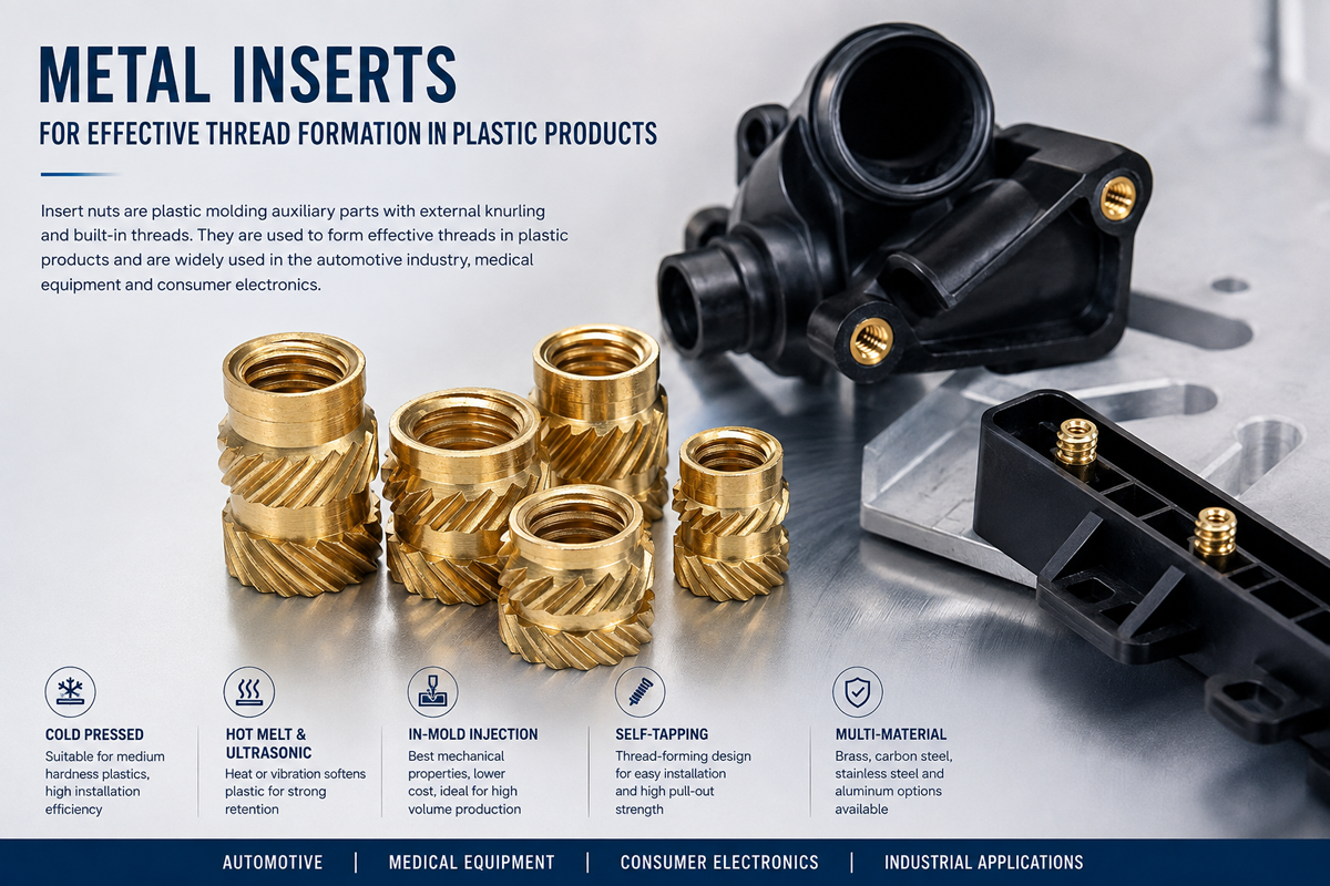
Threaded inserts are metal components designed to create internal machine threads within compatible plastic parts.
They may be installed after molding or incorporated during the molding process.
Depending on the design, inserts can improve:
Thread durability
Resistance to repeated screw installation
Local thread load capacity
Assembly consistency
Maintenance and serviceability
However, the metal thread is only one part of the connection.
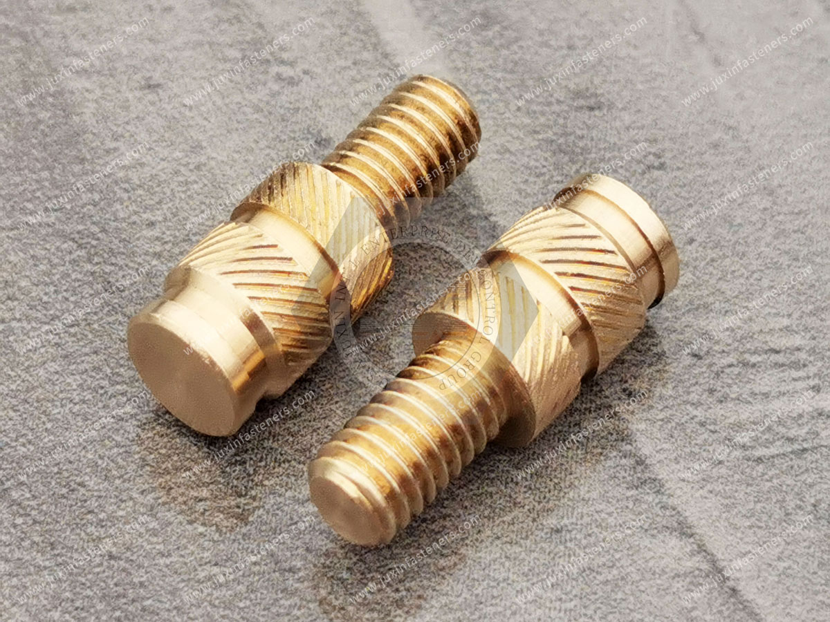
The complete load path is:
Mating screw → Insert internal thread → Insert external retention features → Surrounding plastic → Plastic component structure
The plastic surrounding the insert may determine the limiting strength of the assembly.
Engineering Principle
A stronger metal insert does not necessarily produce a stronger joint if the surrounding plastic boss cracks, creeps or fails first.
The Three Main Installation Methods
Heat-Set Inserts
Installed after molding by applying controlled heat and insertion force.
Press-In Inserts
Installed after molding through mechanical insertion into a compatible hole.
Mold-In Inserts
Positioned in the mold before polymer injection so the molded plastic forms around the insert.
Each method introduces different manufacturing and mechanical considerations.
Heat-Set vs Press-In vs Mold-In Inserts: Technical Comparison
| Selection factor | Heat-set | Press-in | Mold-in |
|---|---|---|---|
| Installation stage | After molding | After molding | During molding |
| Installation mechanism | Controlled heating and insertion | Mechanical interference or retention | Polymer molding around insert |
| Typical process equipment | Thermal insertion equipment | Press or insertion equipment | Mold positioning and retention system |
| Plastic compatibility | Suitable thermoplastics | Compatible plastics and insert designs | Compatible molding processes |
| Pull-out resistance | Design-dependent | Design-dependent | Design-dependent |
| Torque-out resistance | Design-dependent | Design-dependent | Design-dependent |
| Boss stress | Thermal and mechanical effects | Mechanical insertion stress | Molding and cooling effects |
| Automation | Possible | Possible | Possible |
| Secondary insertion operation | Required | Required | Not normally required |
| Mold complexity | Usually lower | Usually lower | May be higher |
| Rework | Process-dependent | Process-dependent | Often more difficult after molding |
| Total installed cost | Production-dependent | Production-dependent | Production-dependent |
Important Limitation
It is technically incorrect to assume that mold-in inserts always provide the highest pull-out resistance or that press-in inserts always have the lowest total cost.
Those conclusions require product-specific and production-representative evidence.
Heat-Set Threaded Inserts: Installation and Design
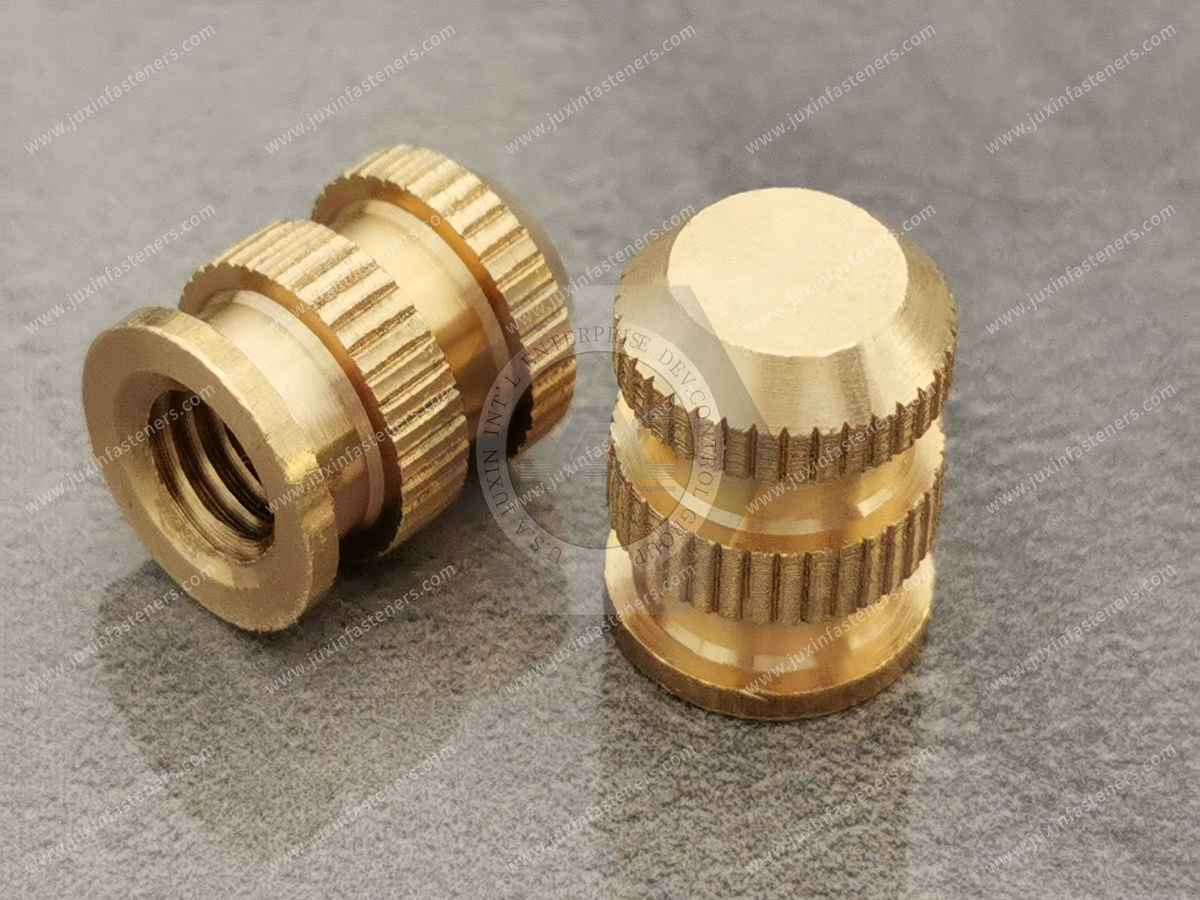
Heat-set inserts are typically installed into suitable thermoplastic components after molding.
A heated installation tip transfers energy to the insert, allowing the surrounding polymer to soften and flow around the insert's external retention features.
After cooling, the polymer provides mechanical retention.
Typical Installation Sequence
Mold the plastic component with the specified pilot hole.
Position the threaded insert.
Apply controlled heat and insertion force.
Advance the insert to the specified depth.
Allow the surrounding polymer to cool.
Inspect the installed insert.
Advantages
Metal internal machine threads
Potentially strong mechanical retention
Compatibility with selected thermoplastics
Post-molding installation flexibility
Suitability for controlled automated insertion
Design and Process Limitations
Excessive temperature can damage the polymer.
Insufficient temperature may prevent proper polymer flow.
Incorrect insertion speed may create voids or poor retention.
Poor boss design can lead to cracking.
Inadequate cooling can affect dimensional stability.
Incorrect insertion depth may interfere with assembly.
Information Gain: Heat-Set Retention Depends on Polymer Flow, Not Heat Alone
The purpose of heat-setting is not simply to melt plastic.
The process must allow sufficient polymer movement around the insert's external features while preserving the integrity of the surrounding boss.
Too little heat may produce incomplete engagement.
Too much heat may degrade the polymer or distort the component.
Engineering Recommendation
Qualify temperature, insertion force, insertion speed, depth and cooling conditions using the actual resin and molded component.
Press-In Threaded Inserts: Installation and Design
Press-in inserts are installed after molding using mechanical force.
Their external features are designed to engage the surrounding plastic.
Depending on the product, retention may be achieved through interference, barbs, knurls or other mechanical features.
Typical Installation Sequence
Mold or prepare the specified hole.
Align the insert.
Apply controlled insertion force.
Seat the insert to the specified depth.
Inspect alignment and surrounding plastic.
Advantages
No thermal insertion stage
Potentially simple equipment requirements
Short installation cycles in suitable applications
Flexibility for post-molding assembly
Compatibility with selected low- and moderate-load designs
Design and Process Limitations
High interference can crack the boss.
Low interference can reduce retention.
Incorrect hole dimensions can cause inconsistent installation.
Some polymers may experience stress relaxation.
Insert misalignment can damage the hole.
High insertion force may distort thin-wall components.
Information Gain: Lower Installation Complexity Does Not Guarantee Lower Production Cost
A press-in insert may require less equipment than a heat-set system.
However, excessive insertion force, boss cracking or inconsistent retention can increase scrap and rework.
Engineering Recommendation
Evaluate installation yield and process stability, not just equipment cost.
Mold-In Threaded Inserts: Installation and Design
Mold-in inserts are positioned within the mold before plastic injection.
Molten polymer flows around the insert's external geometry.
After cooling, the insert becomes mechanically retained within the molded part.
Typical Process Sequence
Position the insert in the mold.
Secure the insert against movement.
Inject the polymer.
Control filling and cooling.
Eject the molded component.
Inspect insert location, thread condition and surrounding plastic.
Advantages
No separate post-molding insertion operation
Potentially robust mechanical retention
Suitability for selected complex molded components
Integration into the molding cycle
Potentially useful for applications requiring specific insert positioning
Design and Process Limitations
Inserts must be positioned accurately.
Mold design may become more complex.
Insert movement during molding can cause defects.
Polymer flow around the insert must be considered.
Cooling shrinkage may introduce local stress.
A defective insert may cause rejection of the molded component.
Insert placement can affect molding cycle time.
Information Gain: Mold-In Retention Is Not Automatically the Highest
A mold-in insert may have excellent retention when polymer fully engages its external features.
However, performance still depends on:
Insert geometry
Polymer type
Reinforcement
Flow behavior
Cooling shrinkage
Boss geometry
Applied load
A poorly designed mold-in insert can perform worse than a properly installed heat-set insert.
Engineering Recommendation
Validate the actual molded assembly rather than relying on a universal ranking of installation methods.
Plastic Material Compatibility: ABS, PC, Nylon, POM and PP
Plastic material selection strongly influences insert retention and installation behavior.
The following guidance is a starting point for engineering evaluation, not a substitute for resin-specific testing.
ABS (Acrylonitrile Butadiene Styrene)
ABS is commonly used for plastic housings and equipment covers.
Potential Insert Options
Heat-set inserts
Compatible press-in inserts
Mold-in inserts
Engineering Considerations
Heat sensitivity
Boss geometry
Hole tolerances
Repeated assembly
Local cracking
Heat-set installation must be controlled to avoid thermal damage.
PC (Polycarbonate)
Polycarbonate is used in selected impact-resistant housings and industrial components.
Potential Insert Options
Heat-set inserts
Compatible press-in inserts
Mold-in inserts
Engineering Considerations
Residual stress
Environmental stress cracking
Heat exposure
Insert interference
Boss design
Engineering Recommendation
Avoid assuming that a high-strength plastic can tolerate excessive insert interference.
PA / Nylon (Polyamide)
Nylon is used in automotive and industrial engineering components.
Potential Insert Options
Heat-set inserts
Compatible press-in inserts
Mold-in inserts
Engineering Considerations
Moisture conditioning
Dimensional variation
Creep
Thermal exposure
Reinforcement
Nylon's moisture content can influence mechanical properties and dimensional behavior.
Glass-Filled Nylon
Glass-filled polyamides are used where increased stiffness or other reinforced-polymer properties are required.
Engineering Considerations
Fiber orientation
Local anisotropy
Mold flow
Boss cracking
Insertion temperature
Mechanical retention
Important Limitation
A process suitable for unfilled nylon may not produce the same results in glass-filled nylon.
POM (Polyoxymethylene / Acetal)
POM is used in precision mechanical plastic components.
Potential Insert Options
Selected press-in designs
Qualified heat-set designs
Mold-in inserts
Engineering Considerations
Polymer flow behavior
Surface characteristics
Retention geometry
Thermal processing limits
Dimensional stability
Engineering Recommendation
Confirm the suitability of the specific insert design and process for the actual POM grade.
PP (Polypropylene)
Polypropylene is used in lightweight housings and industrial components.
Potential Insert Options
Compatible heat-set designs
Selected press-in designs
Mold-in inserts
Engineering Considerations
Creep
Stress relaxation
Thermal expansion
Local deformation
Long-term retention
Engineering Recommendation
Consider long-term load and temperature exposure rather than relying only on initial pull-out testing.
Thermoset Plastics and Composites
Conventional heat-set installation is generally intended for suitable thermoplastics.
Thermosets do not soften and reflow in the same way.
For thermoset and composite components, other insert geometries or installation methods may be necessary.
Engineering Recommendation
Do not assume that a heat-set insert designed for ABS or nylon is suitable for a thermoset composite.
Boss Design and Pilot Hole Engineering
The plastic boss surrounding the insert is critical to joint reliability.
Pilot Hole Diameter
The required hole diameter depends on:
Insert outside geometry
Polymer
Installation method
Molding tolerances
Desired retention
Oversized Holes
May cause:
Reduced insert engagement
Low pull-out resistance
Insert rotation
Poor alignment
Undersized Holes
May cause:
Excessive insertion force
Boss cracking
Distortion
Threaded insert damage
Boss Outside Diameter
The boss must provide sufficient surrounding material to resist the required loads.
However, there is no universal boss diameter ratio suitable for every insert and polymer.
Engineering Recommendation
Use the selected insert's validated design guidance and confirm performance with the actual molded part.
Boss Wall Thickness
Insufficient wall thickness may cause cracking or pull-through.
Excessive wall thickness may introduce molding defects, sink marks or cooling-related problems.
Hole Depth
For blind holes, the depth must accommodate:
Insert length
Installation movement
Any required clearance
Mating screw penetration
Avoid Screw Bottoming
A screw that bottoms against the insert or blind-hole base can create unintended axial loading.
Engineering Recommendation
Verify screw length and thread engagement in the assembled condition.
Edge Distance and Nearby Features
Bosses positioned too close to edges, ribs or thin walls may have reduced structural support.
Engineering Recommendation
Review the local geometry and load path rather than treating the insert as an isolated component.
Threaded Insert Failure Modes
Pull-Out Failure
The insert is extracted from the plastic.
Potential causes:
Inadequate external engagement
Weak surrounding polymer
Incorrect pilot hole
Poor installation
Excessive axial load
Torque-Out Failure
The insert rotates within the plastic.
Potential causes:
Insufficient anti-rotation geometry
Inadequate polymer engagement
Incorrect installation
Excessive assembly torque
Boss Cracking
The plastic surrounding the insert cracks.
Potential causes:
Excessive interference
Thin boss walls
Residual molding stress
Incompatible installation conditions
Thermal or environmental exposure
Plastic Creep and Stress Relaxation
Some polymers may deform gradually under sustained load.
Potential effects:
Reduced insert retention
Joint movement
Preload changes
Long-term dimensional variation
Thermal Cycling
Different thermal expansion behavior between metal and plastic can affect the interface.
Engineering Recommendation
Validate the joint over the intended temperature range.
Repeated Assembly Damage
Although metal threads can support repeated screw installation, the insert-to-plastic interface may still fail if subjected to excessive torque or load.
Engineering Recommendation
Separate thread durability from insert retention when defining performance requirements.
Mechanical Validation: Pull-Out, Torque-Out and Assembly Testing
Testing should be performed on representative assemblies.
Pull-Out Testing
Evaluates resistance to axial extraction.
Torque-Out Testing
Evaluates resistance to insert rotation within the plastic.
Assembly Torque Testing
Evaluates the behavior of the insert and mating screw during tightening.
Repeated Assembly Testing
May be required for serviceable products.
Thermal Cycling
May be required for temperature-sensitive applications.
Environmental Conditioning
May be required for moisture-sensitive polymers or chemically exposed assemblies.
Important Testing Principle
Results depend on:
Polymer grade
Reinforcement
Moisture condition
Boss design
Hole geometry
Insert geometry
Installation process
Test method
A generic insert strength value should not be applied to a different plastic or boss design without validation.
Manufacturing Engineering: Choosing the Best Process for Production
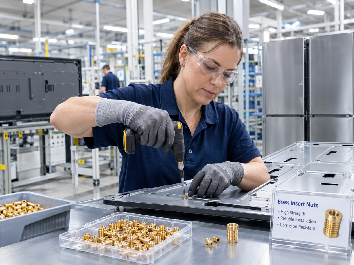
The installation method must fit the actual production workflow.
Heat-Set Production
Relevant factors include:
Heating equipment
Insert temperature
Insertion speed
Depth control
Cooling time
Tool wear
Process monitoring
Press-In Production
Relevant factors include:
Insertion force
Alignment
Hole variation
Press equipment
Boss support
Inspection
Mold-In Production
Relevant factors include:
Mold loading
Insert orientation
Insert retention during injection
Mold cycle time
Automated insert placement
Scrap risk
Production Manager's Decision
A production manager should compare the installation methods using:
Cycle time
Equipment investment
Operator requirements
Automation compatibility
Defect rate
Rework
Maintenance
Production flexibility
Information Gain: Production Yield Can Change the Best Insert Choice
A heat-set insert may have a higher installation equipment cost but deliver better production consistency for a particular plastic component.
A press-in insert may have a lower equipment cost but create more defects if the boss design is unsuitable.
A mold-in insert may eliminate a secondary insertion operation but increase molding complexity.
Engineering Lesson
The best process is the one that achieves the required joint performance with acceptable production cost and quality.
Total Installed Cost Comparison
Purchasing teams should compare the cost of the complete accepted threaded attachment point.
Heat-Set Cost Elements
Insert price
Heating equipment
Installation labor
Cycle time
Energy
Inspection
Scrap and rework
Press-In Cost Elements
Insert price
Press equipment
Installation labor
Cycle time
Tooling
Inspection
Scrap and rework
Mold-In Cost Elements
Insert price
Mold complexity
Insert loading
Mold cycle time
Automation
Inspection
Scrap and rework
Total Installed Cost Framework
Total Installed Cost per Accepted Part = (Insert Cost + Installation Cost + Tooling Allocation + Inspection Cost + Scrap and Rework Cost) ÷ Accepted Part Quantity
This calculation helps distinguish unit insert cost from the cost of producing an acceptable plastic assembly.
Industrial Application Selection
Automotive and EV Components
Potential applications include:
Interior plastic housings
Battery-related electronics housings
Sensor enclosures
Charging equipment housings
Selected noncritical mounting components
Engineering Priorities
Vibration
Thermal cycling
Material compatibility
Assembly torque
Long-term retention
Important Limitation
Threaded inserts must not be assumed suitable for crash-critical or high-voltage safety-related joints without application-specific qualification.
Electronics and Electrical Equipment
Potential applications include:
Electronic housings
Communication equipment
Control boxes
Electrical enclosure components
Engineering Priorities
Compact boss design
Repeatable assembly
Dimensional stability
Thread durability
Production automation
Industrial Machinery
Potential applications include:
Machine covers
Automation equipment
Protective housings
Service panels
Engineering Priorities
Maintenance cycles
Vibration
Chemical exposure
Installation consistency
Medical and Laboratory Equipment
Potential applications include suitable equipment housings and serviceable panels.
Engineering Priorities
Material compatibility
Cleaning exposure
Precision
Repeatable assembly
Customer-specific requirements
Consumer and Commercial Products
Potential applications include:
Appliance housings
Plastic equipment covers
Electronic assemblies
Modular components
Engineering Priorities
High-volume production
Low scrap
Cost
Assembly speed
Serviceability
Selecting Threaded Inserts by Design Requirement
| Design requirement | Selection approach |
|---|---|
| Thermoplastic housing with post-mold access | Evaluate heat-set and press-in |
| High-volume molding with suitable mold design | Evaluate mold-in and automated post-mold insertion |
| Tight boss geometry | Validate insert geometry and local stress |
| Frequent service | Validate thread and insert retention over repeated cycles |
| High torque requirement | Compare tested torque-out performance |
| High axial load | Compare tested pull-out performance |
| Glass-filled polymer | Evaluate fiber orientation and process compatibility |
| Temperature cycling | Validate metal-to-plastic interface |
| Lowest production cost | Compare total installed cost and yield |
| Custom OEM design | Use drawing-based engineering review |
Relevant International Thread Standards
The applicable thread specification depends on the insert and mating screw.
ISO 261
General-purpose metric screw thread plan.
ISO 965 Series
ISO metric screw thread tolerances.
ASME B1.1
Unified inch screw threads.
These standards govern thread systems and do not independently define the retention performance of a threaded insert installed in plastic.
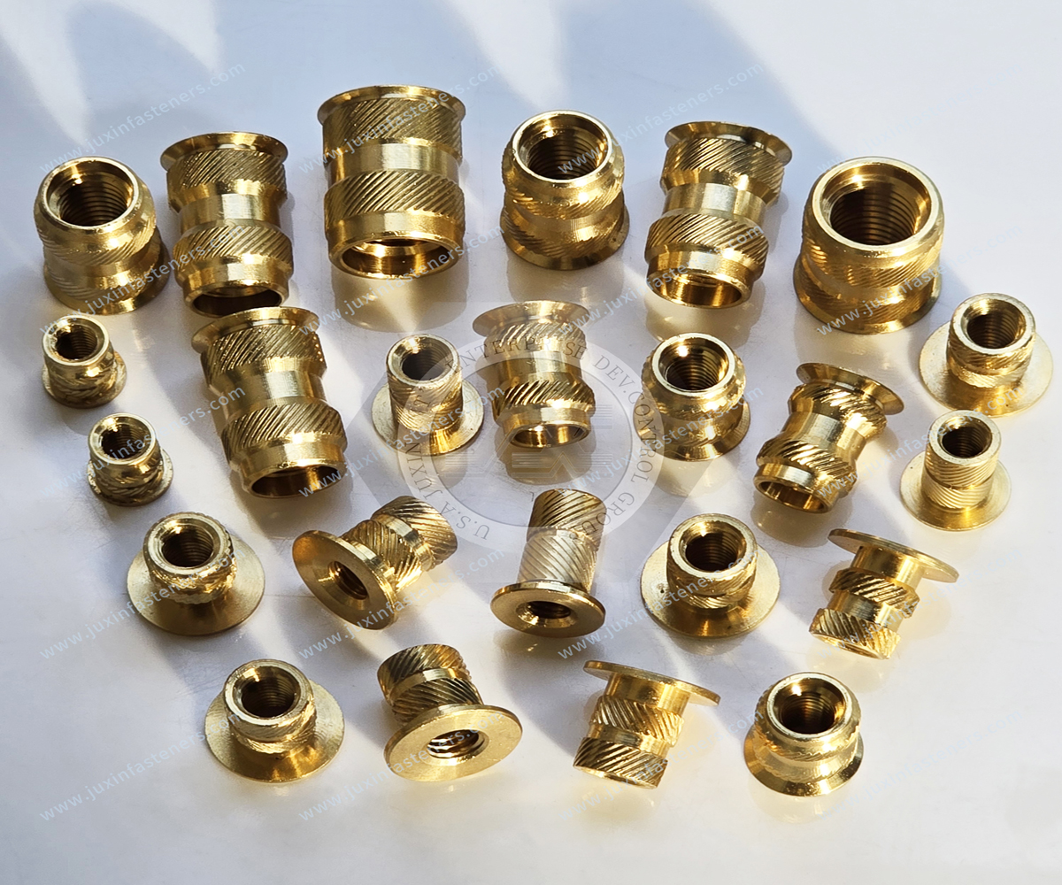
Metric and Inch Thread Selection
Plastic threaded inserts may be specified with metric or unified inch internal threads.
For nominal diameter reference only:
M3 ≈ 0.118 inch
M4 ≈ 0.157 inch
M5 ≈ 0.197 inch
M6 ≈ 0.236 inch
These conversions are reference values only.
Metric, UNC, UNF, BSW and BSF thread systems are not directly interchangeable.
OEM Supplier Qualification and Procurement Considerations
For a new plastic threaded insert supplier, evaluate more than the nominal thread size.
Product Requirements
Insert drawing
Internal thread
External retention geometry
Material
Surface finish
Dimensional tolerances
Application Requirements
Polymer grade
Reinforcement
Boss geometry
Pilot hole
Installation method
Assembly torque
Mechanical performance
Production Requirements
Prototype quantity
Annual volume
Installation equipment
Inspection
Packaging
Lead time
Change control
Commercial Requirements
MOQ
Unit price
Tooling cost where applicable
Production forecast
Delivery schedule
Supplier qualification documentation
OEM RFQ Checklist for Plastic Threaded Inserts
| RFQ item | Information to provide |
|---|---|
| Insert drawing | Part number and revision |
| Installation method | Heat-set, press-in or mold-in |
| Thread designation | Metric or unified inch |
| Insert material | Brass, stainless steel or other specified material |
| External geometry | Knurl, barb or retention design |
| Plastic material | Resin grade and reinforcement |
| Boss dimensions | Outside diameter and height |
| Pilot hole | Diameter, depth and tolerances |
| Installation conditions | Temperature, force, stroke or molding method |
| Mechanical requirements | Pull-out and torque-out |
| Mating screw | Thread, length and tightening conditions |
| Service conditions | Temperature, moisture, chemicals and vibration |
| Quality documentation | Customer-specific requirements |
| Prototype quantity | Sample demand |
| Annual volume | Forecast quantity |
| MOQ | Commercial confirmation |
| Lead time | Required delivery schedule |
| Packaging | Bulk or protected packaging |
Frequently Asked Questions
Are mold-in inserts stronger than heat-set inserts?
Not necessarily. Performance depends on the insert geometry, polymer, boss design and manufacturing conditions.
Are press-in inserts cheaper than heat-set inserts?
They may require simpler equipment, but total installed cost depends on cycle time, scrap, inspection and production volume.
Can heat-set inserts be used in ABS?
Suitable heat-set inserts may be used in compatible ABS components when the temperature and installation process are qualified.
Can threaded inserts be installed in glass-filled nylon?
Yes, selected designs may be suitable, but reinforcement, fiber orientation and installation conditions require evaluation.
What causes threaded inserts to spin in plastic?
Possible causes include inadequate anti-rotation geometry, poor polymer engagement, incorrect hole size or excessive assembly torque.
Why do plastic bosses crack during insert installation?
Potential causes include excessive interference, insufficient wall thickness, molding stress or incompatible installation parameters.
Can metal threaded inserts support repeated assembly?
They can provide durable metal threads, but repeated assembly must remain within the limits of the complete insert-to-plastic joint.
Which insert is best for high-volume injection molding?
The best method depends on molding cycle time, insert loading, automation, joint requirements and production economics.
Can a press-in insert replace a heat-set insert?
Sometimes, but the hole, boss, retention geometry and required mechanical performance must be revalidated.
What information is required for an OEM quotation?
Provide the insert drawing, polymer, boss geometry, installation method, mechanical requirements, quality expectations and forecast demand.
Juxin Fasteners: Threaded Inserts for Plastic OEM Applications
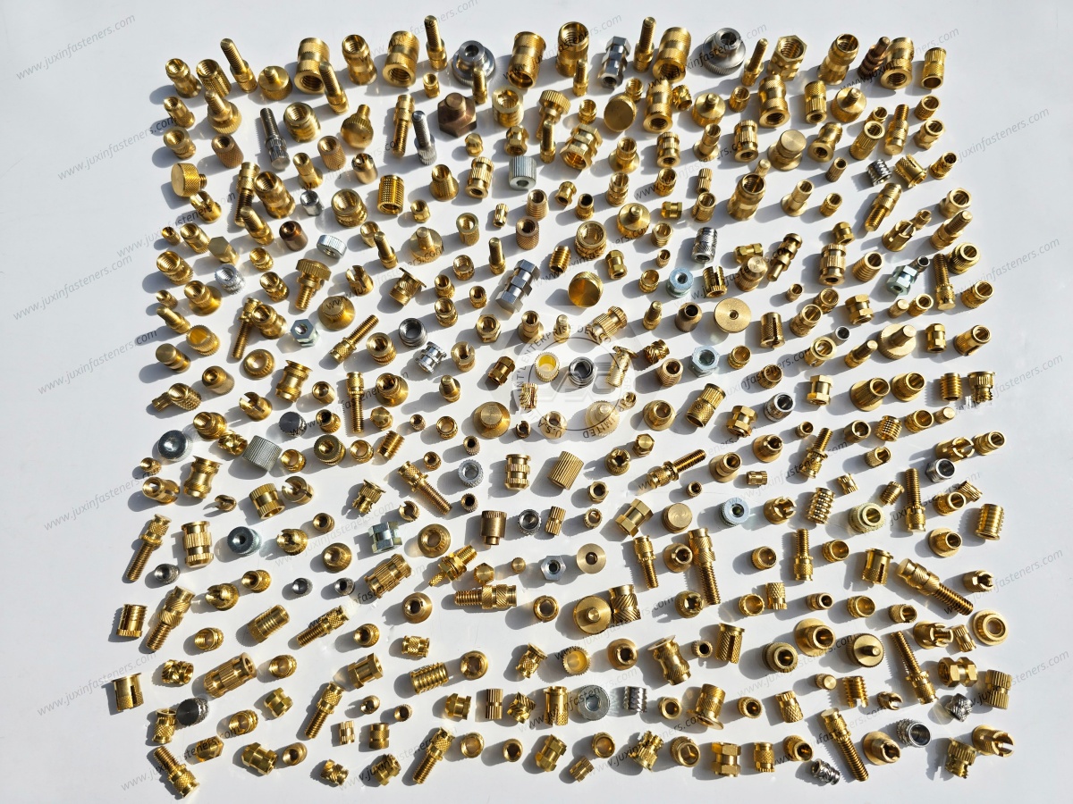
Juxin Fasteners welcomes inquiries for standard and custom threaded inserts used in suitable plastic components and industrial OEM assemblies.
Relevant product categories include:
Heat-set threaded inserts
Press-in threaded inserts
Mold-in threaded inserts
Brass threaded inserts for plastic
Stainless steel threaded inserts for plastic
Knurled threaded inserts
Custom OEM threaded insert designs
Specific product configurations, material grades, external geometries, manufacturing feasibility,
inspection documentation, MOQ and lead times require confirmation against customer drawings.
Request an OEM Plastic Threaded Insert Quotation
Are you developing a plastic housing, selecting threaded inserts for an injection molded component, replacing an existing insert design or evaluating a supplier for high-volume production?
Juxin Fasteners welcomes drawing-based inquiries from design engineers, mechanical engineers, structural engineers, manufacturing engineers,
production managers, purchasing specialists, procurement managers, supplier development teams and supply chain managers.
Please provide:
Insert drawing + thread designation + insert material + plastic resin and reinforcement + boss geometry + pilot hole dimensions
+ installation method + pull-out and torque-out requirements + service environment + quality documentation + prototype quantity + annual volume + packaging + delivery schedule.
Our team can review the supplied information and confirm available product options, technical feasibility and quotation conditions.
Company: Juxin Fasteners
Website: https://www.juxinfasteners.com/
Email: info@juxinfasteners.com
Send your plastic threaded insert drawings and OEM RFQ to Juxin Fasteners for technical confirmation and quotation.
Contact Us
Tel.:
+86 020 8621 0320
+86 020 3121 6067
E-mail:
Technical Support:
Navigation
SEND INQUIREY



