
Call Us
+86 136 6007 9809
Call Us
+86 136 6007 9809

Apr. 08, 2026
High-Strength Automotive Screws and Threaded Inserts for Lightweight OEM Assemblies
Modern automotive engineering increasingly combines high-strength fastening requirements with lightweight materials,
compact electronic systems and efficient mass-production processes.
Vehicle manufacturers use engineering plastics, aluminum alloys, magnesium alloys and composite materials to reduce weight,
integrate components and optimize packaging.
However, these materials can present fastening challenges.
Directly formed threads in a lightweight component may be vulnerable to:
Thread stripping
Local material deformation
Reduced thread engagement
Wear after repeated servicing
Installation damage
Loss of joint preload
Inconsistent tightening performance
High-strength automotive screws and threaded inserts can be combined to create serviceable mechanical
connections where the base material alone cannot provide the required thread performance.
A properly selected insert provides a defined internal thread, while the mating screw supplies the clamping force required by the joint.
The resulting connection must be designed as a complete system.
Its performance depends on the screw, insert, base material, installation method, geometry, operating loads and assembly process.
For automotive design and structural engineers, the main questions involve strength, thread engagement, insert retention, material compatibility and joint durability.
For manufacturing engineers and production managers, the priorities include installation repeatability, cycle time, automated handling, defect prevention and production cost.
For procurement development teams, purchasing managers and supply chain managers, the decision also involves technical feasibility,
drawing compliance, tooling, MOQ, quality documentation, lead time and supply continuity.
Juxin Fasteners welcomes OEM inquiries for automotive screws, threaded inserts and drawing-specific fastening components.
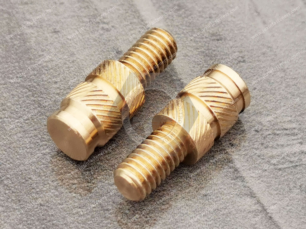
What Are Automotive Threaded Inserts?
Automotive threaded inserts are mechanical components installed into a host material to provide an internal thread for a mating screw or bolt.
Depending on the design, the insert may be installed into:
Engineering plastics
Aluminum alloys
Magnesium alloys
Composite components
Selected metal housings
The purpose is to establish a threaded interface suitable for the specified mechanical and service requirements.
Common Insert Materials
Brass
Carbon steel
Stainless steel
Selected aluminum alloys
Common Insert Designs
Heat-set threaded inserts
Ultrasonic threaded inserts
Molded-in threaded inserts
Cold-press inserts
Self-tapping threaded inserts
Wire thread inserts
Solid threaded inserts
Application-specific OEM inserts
Important Engineering Clarification
A threaded insert does not automatically increase the strength of every connection.
The insert may provide stronger internal threads, but the overall joint can still fail through:
Insert pull-out
Insert rotation
Base material cracking
Boss splitting
Screw failure
Thread stripping
Joint separation
Engineering Recommendation
Evaluate the complete screw-insert-base material assembly rather than selecting the insert solely by nominal thread size.
How High-Strength Screws and Threaded Inserts Work Together
A threaded insert provides the female thread.
The mating screw provides the clamping action.
The host material supports the insert and transfers loads into the surrounding component.
The Load Path
In a typical assembly, load is transferred through:
The screw head or bearing surface
The clamped components
The screw threads
The insert's internal threads
The insert's external retention features
The surrounding base material
Each interface must be suitable for the required loading conditions.
Important Design Principle
A high-strength screw can exceed the capacity of the insert or the surrounding plastic or aluminum.
For example, increasing screw property class does not automatically increase insert pull-out strength.
It may instead increase the risk of damaging the host material if the tightening procedure is not adjusted.
Engineering Recommendation
Select the screw and insert as a compatible fastening system with a validated tightening specification.
High-Strength Automotive Screws: Material and Property Class Selection
High-strength automotive screws may be specified using metric property classes such as 8.8, 10.9 or 12.9.
ISO 898-1 defines mechanical property requirements for applicable carbon steel and alloy steel bolts, screws and studs.
However, the correct property class depends on the joint.
Selection Factors
Required clamp load
Joint stiffness
External loading
Fatigue requirements
Screw diameter
Thread engagement
Mating insert material
Host material strength
Corrosion environment
Important Engineering Clarification
A class 12.9 screw is not automatically more suitable than a class 8.8 or 10.9 screw for a threaded insert installed in plastic.
The limiting failure mode may be insert pull-out, plastic deformation or boss cracking rather than screw tensile failure.
Engineering Recommendation
Determine the weakest relevant element in the complete joint before increasing screw strength.
Thread Compatibility
Metric threads should follow the applicable ISO thread specifications, including ISO 261 and the ISO 965 series where relevant.
Unified inch threads, including UNC and UNF, are covered by ASME B1.1.
Metric-to-Inch Nominal Diameter References
| Metric thread | Approximate nominal diameter |
|---|---|
| M3 | 0.118 in |
| M4 | 0.157 in |
| M5 | 0.197 in |
| M6 | 0.236 in |
| M8 | 0.315 in |
| M10 | 0.394 in |
These values are dimensional references only.
Metric, UNC, UNF, BSW and BSF threads are not directly interchangeable.
Special inch-thread availability must be confirmed against the drawing.
Automotive Engine and Transmission Housing Applications
Engine and transmission assemblies may contain aluminum or other lightweight housings requiring durable threaded connections.
Potential applications include:
Engine covers
Transmission housings
Gearbox components
Motor housings
Auxiliary equipment mounting
Serviceable housing attachments
Engineering Challenges
Repeated maintenance
Thermal cycling
Vibration
Thread wear
Material expansion
Local stress concentration
Thread Reinforcement Options
Depending on the design, suitable solutions may include:
Wire thread inserts
Solid threaded inserts
Self-tapping threaded inserts
Application-specific repair inserts
Engineering Recommendation
Determine whether the insert is intended for original equipment manufacturing or thread repair.
The installation geometry, machining process and qualification requirements may differ.
Important Limitation
Not every insert is suitable for high-temperature or safety-critical engine applications.
Material compatibility and joint validation are required.
Automotive Chassis and Suspension Fastening Applications
Automotive chassis and suspension systems experience dynamic loading, vibration and environmental exposure.
Potential applications include:
Suspension brackets
Structural supports
Subframes
Reinforcement components
Selected mounting interfaces
High-strength screws may be required for some of these connections.
However, the use of threaded inserts in load-bearing structures requires careful engineering assessment.
Engineering Considerations
Static and dynamic loads
Fatigue
Insert retention
Base material strength
Joint stiffness
Corrosion
Assembly preload
Important Safety Clarification
A threaded insert is not automatically suitable for a suspension or other safety-critical structural connection.
The connection must be approved and validated for the specific vehicle application.
Engineering Recommendation
For structural automotive joints, prioritize the complete approved joint design rather than assuming a reinforced internal thread is sufficient.
Automotive Electronics and Sensor Housing Applications
Modern vehicles contain numerous electronic systems requiring compact and serviceable mechanical connections.
Potential applications include:
Electronic control unit housings
Sensor brackets
Camera modules
Battery management system housings
Infotainment modules
Interior electronic assemblies
Engineering plastics and aluminum housings are common in these applications.
Brass Threaded Inserts for Plastic Housings
Brass inserts may be considered where reusable metal threads are required in thermoplastic components.
Potential Advantages
Defined internal threads
Suitable corrosion resistance in many environments
Compatibility with selected heat-set and molded-in designs
Repeated screw installation capability when properly designed
Engineering Limitations
Boss cracking
Insert rotation
Pull-out
Thermal expansion mismatch
Plastic creep
Excessive tightening torque
Electrical Design Considerations
A metallic insert may provide electrical conductivity, but electrical continuity is not automatically guaranteed.
Contact conditions, coatings, mating materials and the electrical system design must be evaluated.
Engineering Recommendation
For electronic housings, assess both mechanical retention and electrical requirements.
EV Battery Pack and Lightweight Structural Applications
Electric vehicle manufacturers increasingly use lightweight materials in battery and motor-related assemblies.
Potential threaded insert applications include:
Battery enclosure attachments
Motor housings
Aluminum structural components
Magnesium alloy housings
Electronic module supports
Serviceable auxiliary assemblies
Engineering Challenges
Dissimilar material compatibility
Thermal expansion
Corrosion
Thread wear
Assembly access
Maintenance
Joint preload retention
Important EV Design Clarification
A threaded insert does not automatically provide electrical isolation, sealing or thermal management.
Those functions require separate design features and validation.
Wire Thread Inserts for Aluminum Applications
Wire thread inserts, also known as helical coil thread inserts, create an internal thread within a prepared tapped hole.
They may be considered for:
Aluminum housings
Magnesium components
Thread repair
Repeatedly serviced threaded connections
Potential Advantages
Reinforced internal thread interface
Reduced wear of the host thread in suitable applications
Repair capability
Standard mating screw engagement where properly specified
Engineering Limitations
Correct tapped-hole preparation is essential
Insert length must be selected
Installation tooling may be required
Tang handling may apply to certain designs
Host material strength remains a limiting factor
Important Clarification
Wire thread inserts do not inherently prevent screw loosening.
Joint preload, external loading and locking requirements must be evaluated separately.
Engineering Recommendation
Confirm the wire insert design, installed length, thread form and host material requirements before approving an EV application.
Threaded Insert Selection by Base Material
Different host materials require different retention mechanisms.
| Base material | Potential insert solution | Key design concern |
|---|---|---|
| Thermoplastic | Heat-set or ultrasonic insert | Boss geometry and thermal process |
| Injection-molded plastic | Molded-in insert | Mold positioning and plastic flow |
| Suitable plastic | Cold-press insert | Interference and cracking |
| Selected plastic or composite | Self-tapping insert | Installation stress and material behavior |
| Aluminum alloy | Wire or solid insert | Thread engagement and host material strength |
| Magnesium alloy | Application-specific insert | Corrosion and local material strength |
| Composite material | Validated insert system | Delamination and local reinforcement |
Engineering Recommendation
Do not assume one insert geometry or installation method is suitable for all lightweight materials.
Heat-Set Threaded Inserts
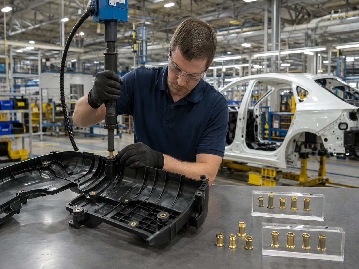
Heat-set inserts are commonly used in suitable thermoplastic components.
The insert is heated and pressed into a prepared hole, allowing surrounding thermoplastic material to soften and flow around its retention features.
Potential Advantages
Defined internal metal threads
Good retention when properly designed
Suitable for selected automated installation processes
Useful for serviceable plastic assemblies
Critical Process Variables
Insert temperature
Installation force
Hole geometry
Boss dimensions
Insertion depth
Cooling conditions
Material compatibility
Common Failure Risks
Excessive plastic melting
Poor material flow
Boss deformation
Incomplete insertion
Insert misalignment
Low pull-out or torque-out resistance
Engineering Recommendation
Validate the complete thermal insertion process using the actual molded plastic material and component geometry.
Ultrasonic Threaded Inserts
Ultrasonic insertion uses controlled mechanical vibration to generate localized heat in suitable thermoplastics.
Potential Advantages
Rapid installation in compatible materials
Localized material softening
Potential integration with automated equipment
Critical Process Variables
Ultrasonic energy
Installation pressure
Horn alignment
Insert geometry
Plastic formulation
Boss design
Important Limitation
Ultrasonic insertion is not suitable for every plastic or insert design.
Engineering Recommendation
Compare ultrasonic and heat-set installation using actual production samples and measured retention performance.
Cold-Press Threaded Inserts
Cold-press inserts rely on mechanical interference or other retention features without intentionally heating the surrounding material during installation.
Potential Advantages
Relatively simple installation
No dedicated thermal insertion stage
Potentially efficient assembly for suitable materials
Engineering Risks
Boss splitting
Excessive insertion force
Material stress
Reduced retention
Inconsistent hole dimensions
Engineering Recommendation
Cold-press inserts should be selected only where the host material and boss geometry can tolerate the installation forces.
Molded-In Threaded Inserts
Molded-in inserts are positioned in the mold before plastic injection.
Plastic flows around the insert during molding.
Potential Advantages
Integrated manufacturing process
No separate post-molding insertion operation
Design flexibility for selected components
Defined insert position when molding is controlled
Engineering Challenges
Insert movement during molding
Plastic flow around retention features
Molding cycle time
Mold tooling complexity
Thermal expansion
Flash or contamination of internal threads
Important Clarification
Molded-in inserts do not automatically provide maximum retention strength.
Retention depends on insert geometry, plastic material, surrounding wall thickness and molding conditions.
Engineering Recommendation
Evaluate molded-in inserts against alternative installation methods using total manufacturing cost and validated mechanical performance.
Self-Tapping Threaded Inserts
Self-tapping inserts have an internal thread for the mating screw and external features that cut or form engagement with the host material during installation.
Important Technical Clarification
The internal thread is normally already present.
The self-tapping action concerns the insert's external engagement with the host material.
Potential Applications
Suitable plastic components
Selected composite materials
Certain metal applications, depending on insert design
Thread repair or reinforcement
Potential Advantages
Reduced need for a separate host tapping operation in suitable designs
Defined internal threads
Mechanical retention through external engagement
Engineering Risks
Excessive installation torque
Host material cracking
Incorrect pilot-hole size
Insert misalignment
Insufficient retention
Engineering Recommendation
Specify the pilot-hole geometry and installation procedure according to the actual insert design and host material.
Pull-Out Resistance vs Torque-Out Resistance
Two important performance characteristics for many threaded insert applications are pull-out resistance and torque-out resistance.
Pull-Out Resistance
The axial force required to extract the insert from the host material under defined test conditions.
Torque-Out Resistance
The torque required to rotate the installed insert relative to the host material under defined conditions.
Why Both Matter
An insert may resist axial extraction but still rotate during screw tightening.
Alternatively, it may resist rotation but pull out under axial loading.
Engineering Recommendation
Specify both characteristics where relevant to the application.
Important Clarification
Pull-out and torque-out values depend on:
Insert geometry
Host material
Hole dimensions
Boss geometry
Installation method
Test configuration
Temperature
Conditioning
Values from different test methods or host materials should not be compared as though they are directly equivalent.
Plastic Boss Design and Wall Thickness
The boss is the surrounding plastic structure that supports the insert.
Its geometry can determine whether the insert performs reliably.
Critical Variables
Boss outside diameter
Hole diameter
Hole depth
Wall thickness
Distance to nearby edges
Insert length
Material formulation
Rib support
Molding conditions
Common Design Risks
Boss Cracking
May occur because of excessive interference, installation stress or insufficient surrounding material.
Insert Pull-Out
May result from inadequate engagement or insufficient material around the insert.
Insert Rotation
May occur when retention features cannot resist the applied tightening torque.
Plastic Creep
Long-term stress and temperature may cause deformation that reduces joint clamp load.
Engineering Recommendation
Use insert-specific boss design guidance and validate the actual molded part.
Information Gain: Stronger Inserts Can Create Weaker Plastic Assemblies
Increasing insert diameter or retention aggressiveness may appear to improve strength.
However, the larger insert may require a larger hole or introduce higher installation stresses.
If the surrounding boss is not redesigned, the result may be cracking or reduced wall strength.
Engineering Recommendation
Optimize the insert and plastic boss together rather than selecting the largest available insert.
Thread Engagement and Screw Length
Correct screw engagement is necessary for reliable fastening.
Design Considerations
Internal thread length
Screw engagement
Screw tip clearance
Blind-hole depth
Insert length
Mating component thickness
Screw head bearing area
Important Limitation
A screw that bottoms in a blind insert may reach the specified tightening torque without developing the intended clamp load.
Engineering Recommendation
Verify screw length and available engagement using the complete assembly stack-up.
Torque Control and Joint Preload
The insert must withstand the tightening process without rotating, pulling out or damaging the host material.
Important Engineering Clarification
Tightening torque is not equal to preload.
The resulting clamp load depends on thread friction, bearing friction and joint conditions.
Engineering Recommendation
Determine tightening requirements using the actual screw, insert and host material assembly.
For Plastic Assemblies
Consider:
Plastic creep
Boss deformation
Thermal expansion
Bearing pressure
Long-term preload relaxation
For Aluminum Assemblies
Consider:
Thread engagement
Local material strength
Galvanic corrosion
Joint settlement
Thermal cycling
Information Gain: Higher Screw Torque Can Reduce Joint Reliability
Increasing torque may improve clamp load only up to the point where another component begins to fail.
In a plastic insert assembly, excessive torque can rotate the insert, crack the boss or damage the mating thread.
Engineering Recommendation
Define the tightening window based on validated assembly performance, not screw property class alone.
Vibration and Loosening Resistance
Automotive assemblies may experience repeated vibration and transverse loading.
Threaded inserts can provide durable internal threads, but they are not inherently anti-loosening devices.
Potential Loosening Mechanisms
Insufficient preload
Joint slip
Plastic creep
Surface settlement
Thermal cycling
Screw rotation
Engineering Recommendation
Where vibration loosening is a concern, evaluate:
Joint stiffness
Target preload
Mating screw
Insert retention
Locking method
Operating temperature
Dynamic loading
Important Clarification
An insert may remain securely retained in the base material while the mating screw loosens.
These are different failure modes and should be evaluated separately.
Corrosion and Dissimilar Material Compatibility
Automotive inserts and screws may be exposed to humidity, road salt, cleaning chemicals or condensation.
Material combinations can create corrosion risks.
Potential Combinations
Steel screw and brass insert
Stainless steel screw and brass insert
Steel screw and aluminum housing
Stainless steel insert and magnesium alloy component
Engineering Considerations
Galvanic compatibility
Surface coatings
Electrical contact
Moisture exposure
Thread friction
Material strength
Environmental sealing
Engineering Recommendation
Evaluate the actual material combination and service environment rather than assuming stainless steel or brass eliminates corrosion risk.
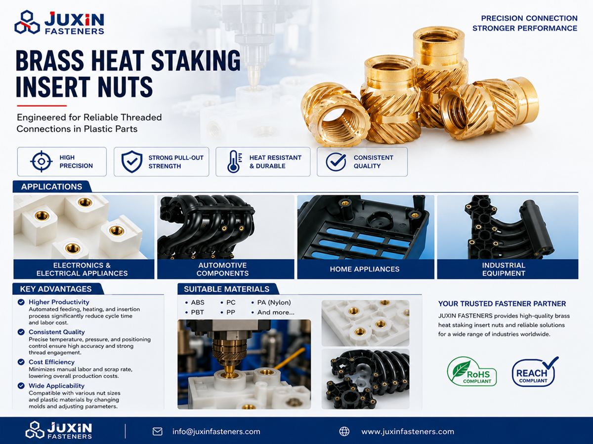
Automated Automotive Assembly Lines
High-volume automotive manufacturing requires consistent insertion and tightening processes.
Potential automation methods include:
CNC-controlled insertion equipment
Robotic handling systems
Heat insertion stations
Ultrasonic insertion equipment
Automated screwdriving systems
In-line inspection
Manufacturing Priorities
Part orientation
Hole consistency
Insert feeding
Insertion depth
Cycle time
Tool wear
Scrap rate
Functional verification
Important Clarification
Not every threaded insert is suitable for automated feeding or robotic installation.
Geometry, packaging and process feasibility must be reviewed.
Engineering Recommendation
Confirm automation requirements during product development rather than after the insert geometry has been finalized.
Information Gain: Insert Installation Cost Can Exceed Insert Purchase Cost
For high-volume production, the total installed cost includes more than the insert unit price.
Relevant factors include:
Insert purchase price
Hole preparation
Installation equipment
Tooling
Cycle time
Inspection
Scrap
Rework
Maintenance
Engineering Recommendation
Compare insertion methods using total cost per accepted assembly rather than insert unit price alone.
Quality Control for Automotive Threaded Inserts
Quality requirements should cover the insert and the installed joint.
Incoming Insert Inspection
Potential checks include:
Material specification
Internal thread accuracy
External dimensions
Retention feature geometry
Surface finish
Coating
Cleanliness
Installation Process Inspection
Potential checks include:
Hole dimensions
Insert orientation
Installation depth
Alignment
Installation force or process parameters
Visible boss damage
Functional Validation
Depending on the application:
Pull-out testing
Torque-out testing
Screw tightening evaluation
Repeated assembly cycling
Thermal cycling
Vibration testing
Corrosion evaluation
Important Qualification Principle
A dimensionally compliant insert may still perform poorly if installed in an unsuitable boss or host material.
Engineering Recommendation
Qualify the installed assembly using representative production materials and processes.
Automotive Quality and Customer-Specific Requirements
Automotive OEMs and Tier suppliers may require additional documentation and production controls.
Potential requirements include:
Approved drawings
Material records
Dimensional reports
Process controls
Traceability
Inspection plans
Engineering change control
Production part approval documentation where specified
IATF 16949
IATF 16949 is a quality management system standard used in the automotive supply chain.
However, supplying automotive components does not automatically establish certification.
Any certification status must be independently verified.
APQP and PPAP
Advanced Product Quality Planning and Production Part Approval Process requirements may apply depending on the customer and project.
The required documentation and submission level must be agreed upon during supplier qualification.
Custom Automotive Screws and Threaded Inserts
OEM programs may require drawing-specific fastening components.
Potential requirements include:
Special thread sizes
Custom insert lengths
Retention feature geometry
Head and flange configurations
Special screw lengths
Material grades
Surface treatments
Installation requirements
Packaging
Traceability
Engineering Recommendation
Provide the insert drawing, mating screw specification and host component geometry.
Custom feasibility, tooling requirements, MOQ and lead time must be confirmed for each project.
Supplier Development and Procurement Evaluation
Procurement teams should assess technical compliance and commercial feasibility together.
Technical Evaluation
Drawing compliance
Material specification
Thread accuracy
Insert geometry
Installation requirements
Pull-out and torque-out performance
Quality documentation
Manufacturing Evaluation
Process feasibility
Tooling
Dimensional consistency
Installation repeatability
Inspection
Engineering change management
Commercial Evaluation
Prototype quantity
MOQ
Annual demand
Unit price
Tooling cost
Lead time
Packaging
Delivery schedule
Supply continuity
Important Commercial Clarification
Specific manufacturing capability, test availability, MOQ, lead time and documentation requirements must be confirmed during RFQ review.
OEM RFQ Checklist
| RFQ item | Information to provide |
|---|---|
| Product drawing | Part number and revision |
| Screw type | Machine screw or specified |
| Screw thread | Metric or inch designation |
| Screw property class | Required mechanical properties |
| Insert type | Heat-set, self-tapping, wire or specified |
| Insert material | Brass, steel, stainless steel or specified |
| Host material | Plastic, aluminum, magnesium or composite |
| Host geometry | Hole, boss and wall dimensions |
| Thread engagement | Required engagement length |
| Installation | Heat, ultrasonic, press, molded-in or other |
| Pull-out requirement | Test method and acceptance criteria |
| Torque-out requirement | Test method and acceptance criteria |
| Tightening | Required torque or assembly process |
| Environment | Temperature, vibration and corrosion |
| Quality | Inspection and documentation requirements |
| Samples | Prototype quantity |
| Annual demand | Volume forecast |
| MOQ | Commercial confirmation |
| Lead time | Required schedule |
| Packaging | Bulk or automated-feed requirements |
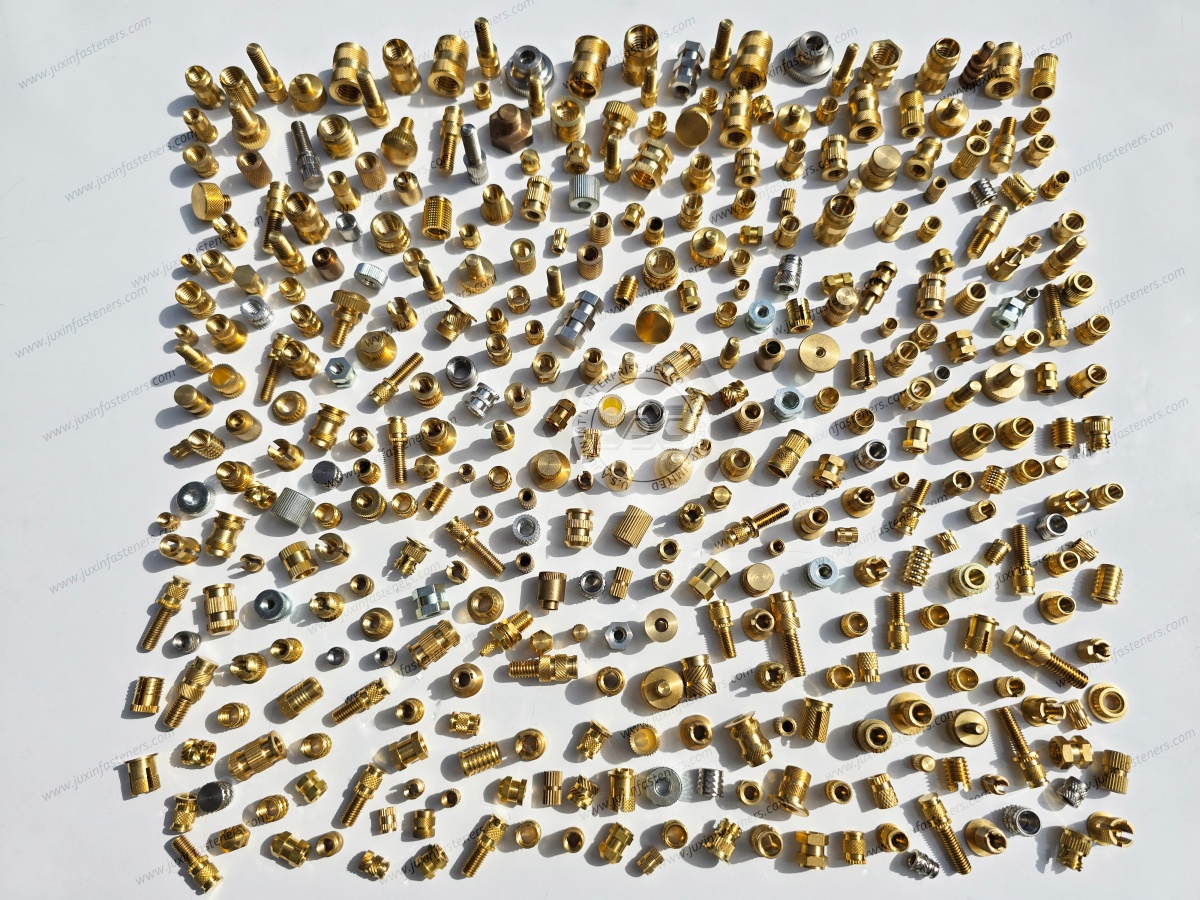
Frequently Asked Questions
What are automotive threaded inserts?
They are components installed in a host material to provide internal threads for mating screws or bolts.
Why are threaded inserts used in automotive plastics?
They may provide more durable threaded interfaces than directly formed plastic threads in suitable designs.
Can high-strength screws be used with brass inserts?
Potentially, but the complete joint must be evaluated. A high-strength screw can exceed the retention capacity of the insert or host material.
What is the difference between heat-set and molded-in inserts?
Heat-set inserts are installed into suitable thermoplastics after molding. Molded-in inserts are positioned in the mold before plastic injection.
What are wire thread inserts used for?
They may reinforce or repair internal threads in suitable metal components, including selected aluminum housings.
Do threaded inserts prevent vibration loosening?
Not automatically. Insert retention and mating screw loosening are separate engineering issues.
How do engineers select insert size?
Selection depends on thread requirements, host material, hole geometry, boss dimensions, loads and installation method.
What is the difference between pull-out and torque-out resistance?
Pull-out resistance concerns axial extraction. Torque-out resistance concerns rotation of the installed insert.
Can threaded inserts be used in EV battery housings?
They may be suitable for selected applications, subject to structural, electrical, environmental and manufacturing validation.
Can Juxin Fasteners review custom automotive insert drawings?
Juxin Fasteners welcomes drawing-based inquiries. Product availability and manufacturing feasibility require confirmation.
Juxin Fasteners: Automotive Screws and Threaded Insert Solutions
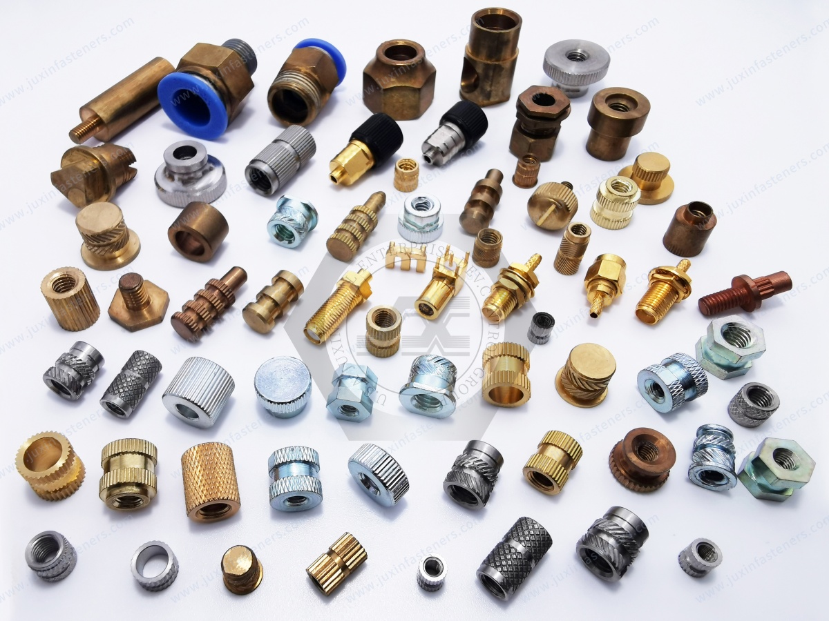
Juxin Fasteners welcomes OEM inquiries involving:
High-strength automotive screws
Machine screws
Self-tapping screws
Brass threaded inserts
Steel threaded inserts
Stainless steel threaded inserts
Thread insert nuts
Wire thread inserts
Blind rivet nuts
Custom automotive fasteners
Drawing-specific CNC machined components
Specific material grades, dimensions, installation methods, quality requirements, MOQ and delivery schedules require confirmation.
Request an Automotive Screw and Threaded Insert Quotation
Are you developing automotive electronics, engine housings, transmission components, EV battery enclosures,
lightweight structures or automated production assemblies requiring reliable threaded connections?
Juxin Fasteners welcomes technical inquiries from:
Automotive design engineers
Structural engineers
Mechanical engineers
Manufacturing engineers
Production managers
Purchasing specialists
Procurement managers
Supplier development teams
Supply chain managers
For technical review, please provide:
Product drawing + mating screw specification + insert thread and dimensions + material requirements + host material
+ hole and boss geometry + installation method + pull-out and torque-out requirements + tightening specification
+ operating environment + inspection criteria + prototype quantity + annual demand + packaging + delivery schedule.
Our team can review the requirements and confirm suitable product options, technical feasibility and quotation conditions.
Company: Juxin Fasteners
Website: https://www.juxinfasteners.com/
Email: info@juxinfasteners.com
Send your automotive screw and threaded insert drawings and OEM RFQ to Juxin Fasteners for technical confirmation and quotation.
Contact Us
Tel.:
+86 020 8621 0320
+86 020 3121 6067
E-mail:
Technical Support:
Navigation
SEND INQUIREY



