
Call Us
+86 136 6007 9809
Call Us
+86 136 6007 9809

Oct. 12, 2023
Internal retaining rings, also called internal circlips or bore retaining rings, are removable mechanical retaining elements installed into grooves inside bores or housings.
Their primary engineering function is axial retention.
Typical applications include retaining or locating:
Rolling bearings
Bushings
Sleeves
Seals
Gears
Mechanical inserts
Pistons or internal machine components
Other components assembled inside a housing or bore
Unlike threaded fasteners, clamp collars, or interference-fit components, an internal retaining ring uses a groove machined into the bore to create a mechanical axial stop.
For design engineers, the correct selection is therefore not based on the retaining ring alone.
The functional system is:
Retaining Ring + Bore Groove + Retained Component + Housing Material + Axial Load + Installation Condition
For procurement and supplier-development teams, this distinction is equally important. A ring with approximately the correct outside diameter is not automatically a functional replacement.
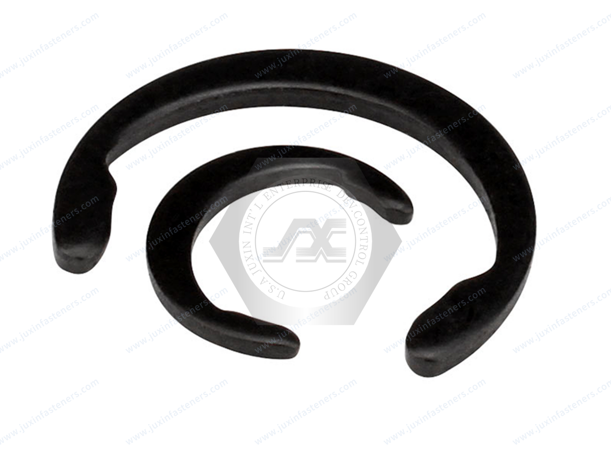
An internal retaining ring is a spring-type retaining component designed to fit into a circumferential groove machined inside a bore.
During installation, the ring is compressed so that its outside diameter becomes small enough to enter the bore.
Once aligned with the groove, the ring expands toward its free condition and seats in the groove.
After installation, part of the ring projects radially inward from the groove and creates an axial shoulder for the retained component.
This creates the basic load path:
Retained Component → Retaining Ring → Groove → Housing
This load path explains why the ring cannot be selected independently from the groove and housing.
Internal and external retaining rings perform related axial-retention functions but operate on different interfaces.
An internal retaining ring is installed in a groove inside a bore or housing.
It is typically compressed during installation.
Common search terms include:
Internal retaining ring
Internal circlip
Internal snap ring
Bore retaining ring
Bearing retaining ring
Retaining ring for bore
An external retaining ring is installed in a groove around a shaft.
It is typically expanded during installation and then allowed to contract into the shaft groove.
The distinction is fundamental:
Internal Ring → Bore Groove
External Ring → Shaft Groove
An internal and external ring with similar nominal sizes are not interchangeable.
DIN 472 defines retaining rings for bores in normal and heavy-type configurations.
These rings are intended for axial retention of components installed inside bores, including applications involving rolling bearings.
For an engineering team, specifying DIN 472 means more than identifying the visual shape of the ring.
The complete design must consider:
Nominal bore size
Ring thickness
Free ring geometry
Groove diameter
Groove width
Groove depth
Edge margin
Installation access
Retained component geometry
Axial load
The applicable standard edition and customer drawing should control the final dimensions and requirements.
Not every internal retaining ring should automatically be specified as DIN 472.
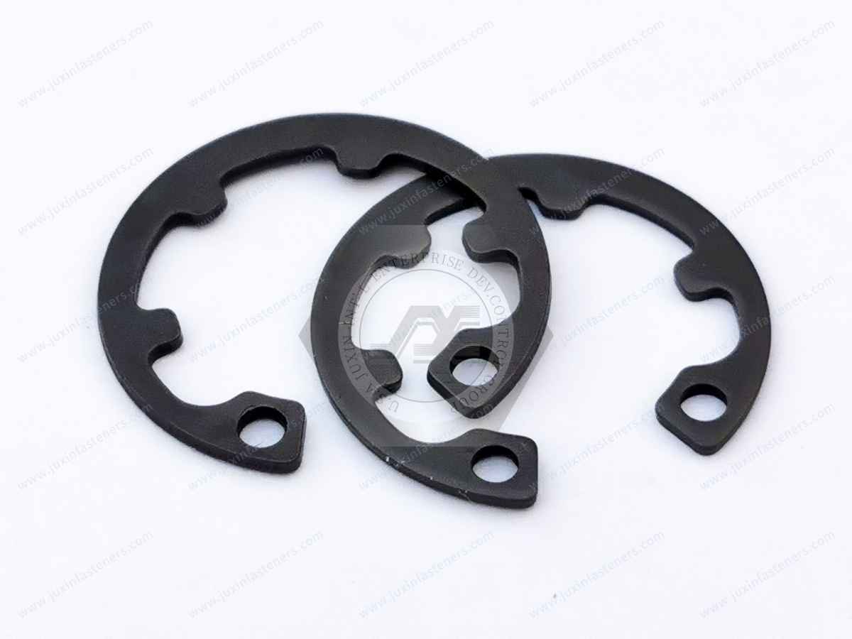
DIN 984 covers retaining rings with lugs for use in bores.
These designs can be relevant where the retained machine component has radiused or chamfered edges and the lug-type geometry is required by the assembly.
Therefore:
DIN 472 Internal Retaining Ring ≠ DIN 984 Lug-Type Internal Retaining Ring
The correct product should be selected from the component interface and groove architecture rather than from the generic term “internal circlip.”
A common sourcing mistake is to treat the retaining ring as an isolated catalog component.
In reality, the groove carries the reaction from the ring into the housing.
This means that axial retention depends on the interaction among:
Ring geometry
Groove geometry
Groove material
Retained component
Component edge geometry
Axial load direction
Assembly clearance
A stronger ring cannot automatically compensate for an unsuitable groove.
Likewise, increasing ring thickness does not automatically solve a retention problem if the limiting condition is groove deformation, housing material, edge margin, or component geometry.
When an axial load pushes the retained component against the internal retaining ring, the ring transfers that load into the groove.
The load path can be simplified as:
Axial Component Load → Ring Contact → Ring Body → Groove Face → Housing
The actual stress distribution depends on the geometry and materials of the complete assembly.
Potential limiting conditions may include:
Ring deformation
Groove deformation
Groove-edge damage
Housing deformation
Retained-component edge deformation
Ring displacement
Installation damage
This is why a generic “ring load capacity” should not be treated as a universal assembly rating.
Groove diameter is one of the critical dimensions in an internal retaining-ring assembly.
It influences:
Ring seating
Radial engagement
Installation
Axial retention
Relationship between the ring and bore
A groove that is too shallow may provide insufficient engagement.
A groove that is too deep can change the installed ring condition and component interface.
The correct groove dimensions should follow the applicable standard, approved drawing, or validated application design.
Groove width must provide sufficient space for the ring while controlling axial movement.
If the groove is too narrow, the ring may:
Fail to seat correctly
Bind during installation
Become damaged
Remain partially outside the groove
If the groove is excessively wide, the assembly may have more axial movement than intended.
Therefore:
Groove Width ≠ Ring Thickness Alone
The required relationship depends on the specified ring, groove tolerance, installation condition, and desired axial clearance.
An internal retaining ring must engage the groove sufficiently to create the intended axial-retention interface.
The groove depth affects how much of the ring is captured by the housing and how much projects inward to retain the component.
Insufficient engagement can increase the risk of displacement.
However, deeper is not automatically better.
Excessive groove depth can change:
Ring position
Radial support
Component contact
Installation behavior
Groove depth should therefore be treated as a controlled engineering dimension.
The material between the retaining-ring groove and the end or edge of the housing contributes to the structural load path.
If the groove is positioned too close to an edge, the remaining material may become a limiting feature.
Relevant factors include:
Housing material
Groove geometry
Axial load
Wall thickness
Edge distance
Temperature
Dynamic loading
Do not evaluate the ring without evaluating the material supporting the groove.
The retained component does not always contact the ring through a perfectly square edge.
Components may include:
Chamfers
Radii
Bearing corner radii
Tapered surfaces
Irregular contact faces
These features can change the contact relationship with the retaining ring.
For example, a large component chamfer may reduce the effective contact area with a conventional retaining ring.
The component drawing should therefore be reviewed together with the ring and groove.
Bearing retention is one of the most important applications for internal retaining rings.
A typical arrangement may include:
Housing Shoulder → Bearing → Internal Retaining Ring
or another assembly-specific arrangement that uses the ring as an axial stop.
The retaining ring can help establish the bearing's axial position, but it should not automatically be treated as a bearing-preload device.
Bearing performance may depend on:
Housing fit
Shaft fit
Shoulder geometry
Bearing type
Internal clearance
Thermal expansion
Operating speed
Axial loading
Preload strategy
Therefore:
Bearing Retention ≠ Bearing Preload
These are separate engineering functions.
A retaining ring does not automatically eliminate all axial movement.
The final axial clearance can be influenced by:
Groove position
Groove width
Ring thickness
Ring geometry
Component width
Housing shoulder position
Manufacturing tolerances
In precision assemblies, engineers should evaluate the complete axial tolerance stack.
If controlled endplay is required, specify it as an assembly requirement rather than assuming the retaining ring alone will establish it.
Some retaining-ring standards distinguish between normal and heavy configurations.
A heavy-type ring should not be selected simply because the application “looks heavy-duty.”
Selection should consider the complete assembly, including:
Available radial space
Groove geometry
Housing material
Axial load
Component geometry
Installation space
Standard dimensional range
A heavier ring may require a different groove and may not be interchangeable with a normal-type ring.
Internal retaining rings are commonly installed by compressing the ring sufficiently to enter the bore and positioning it at the groove.
For designs with plier holes or similar installation features, suitable retaining-ring pliers may be used.
The installation objective is:
Compress Enough to Install → Position at Groove → Allow Ring to Seat Correctly
Excessive deformation during installation should be avoided.
The ring is a spring component, but that does not mean unlimited elastic deformation is acceptable.
Over-compression can contribute to:
Permanent deformation
Reduced seating
Distortion
Installation damage
Functional inconsistency
Installation tooling should match the ring size and geometry.
After installation, the ring should be checked for correct engagement with the groove.
Depending on the assembly and inspection plan, useful checks can include:
Visual confirmation
Circumferential seating review
Position verification
Axial component check
Inspection against the approved drawing
A ring that appears to be inside the bore is not necessarily fully seated.
Partial groove engagement can create an assembly risk.
Design engineers should consider how the ring will actually be installed and removed.
Questions include:
Can retaining-ring pliers reach the installation holes?
Is there sufficient axial working space?
Does another component obstruct the ring?
Can the ring be removed during maintenance?
Will automated assembly be required?
Can the ring be installed without damaging adjacent surfaces?
A technically correct ring and groove can still create production problems if tooling access is ignored.
Some stamped retaining rings can have differences between their two faces because of the manufacturing process.
However, installation orientation should not be generalized into one universal rule for every internal retaining ring.
Orientation requirements depend on:
Ring design
Manufacturing process
Load direction
Groove geometry
Component contact
Supplier or drawing requirements
If orientation is functionally important, it should be documented on the drawing or assembly instruction.
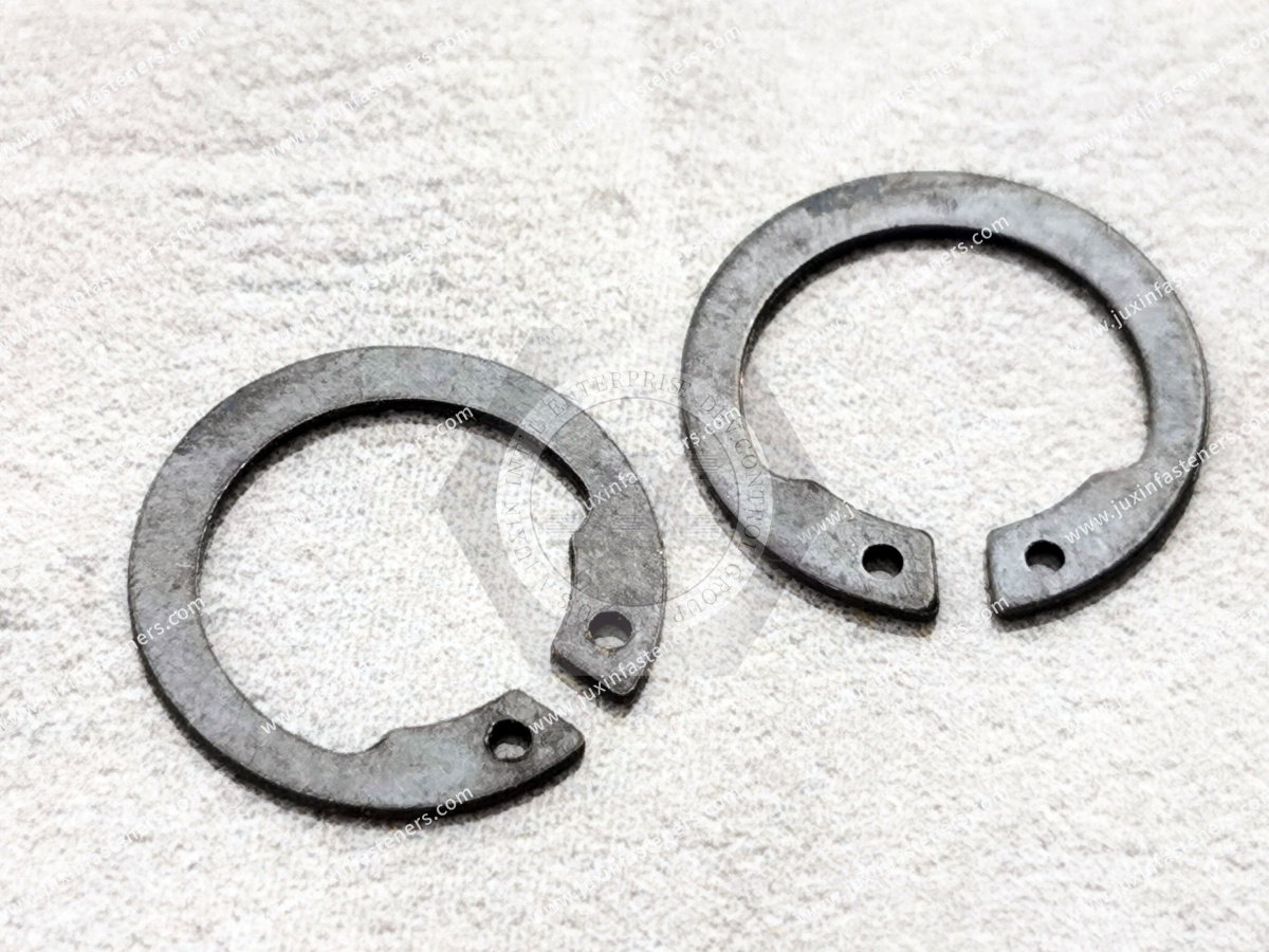
Internal retaining rings require materials capable of providing the elastic behavior needed for installation and retention.
Depending on the design and application, material selection may involve suitable spring steels, stainless steels, or other engineered alloys.
The correct choice depends on:
Required spring behavior
Corrosion environment
Temperature
Ring geometry
Installation deformation
Fatigue considerations
Customer specifications
Material should not be selected solely from ring diameter.
Spring-steel retaining rings are widely used in industrial machinery and general mechanical equipment.
Where corrosion protection is required, an appropriate finish may be applied.
Material and heat-treatment requirements should be controlled according to the applicable product specification, drawing, or validated manufacturing process.
Exact material and hardness requirements should not be inferred from appearance alone.
Stainless steel may be considered for environments where corrosion resistance is important.
Potential applications include:
Food-service equipment
Medical and diagnostic equipment
Laboratory machinery
HVAC equipment
Outdoor equipment
Humid environments
Selected chemical-processing equipment
However:
Stainless Steel ≠ Corrosion-Proof
Performance depends on alloy grade, environment, chloride exposure, temperature, surface condition, and cleaning chemicals.
Depending on material and customer requirements, suitable surface treatments may include appropriate:
Trivalent zinc systems
Zinc-nickel
Phosphate/oil
Black finishes
Other engineered coating systems
Stainless steel passivation where applicable
Surface treatment should be selected according to:
Corrosion exposure
Dimensional requirements
Installation behavior
Ring flexibility
Customer restricted-substance requirements
A coating specification should not be replaced by a color description alone.
Retaining rings are dimensional spring components.
Coating thickness can influence:
Ring thickness
Surface friction
Groove fit
Installation behavior
Corrosion protection
For close-tolerance applications, coating and dimensional requirements should therefore be reviewed together.
A change in coating can require engineering review even when the base ring dimensions appear unchanged.
Salt-spray testing may be used as a comparative corrosion test when required by a customer specification.
However:
Salt-Spray Hours ≠ Guaranteed Field Service Life
Actual corrosion performance depends on the real operating environment, including moisture, chlorides, temperature, chemicals, cyclic exposure, coating damage, and mating materials.
The test method and acceptance requirement should be defined separately from field-life expectations.
Retaining rings can experience deformation during installation and removal.
Repeated reuse should not automatically be assumed.
Relevant considerations include:
Amount of installation deformation
Material
Ring geometry
Previous overload
Corrosion
Wear
Permanent set
Surface damage
For critical applications, reuse policy should be defined by the equipment manufacturer or engineering specification.
These terms can overlap in industrial usage.
“Internal retaining ring” is the clearest functional term for a ring installed in a bore groove.
“Internal circlip” is widely used in European and international industrial markets.
“Internal snap ring” is also common in North American search and sourcing terminology.
However, the terminology alone does not define:
Exact geometry
Standard
Groove
Material
Load capacity
Installation method
For RFQs, the drawing or applicable standard should take precedence over the generic product name.
A spiral retaining ring uses a different geometry from a conventional stamped internal circlip.
The two may differ in:
Cross-section
Installation method
Groove interaction
Axial space
Removal method
Load distribution
They should not be treated as automatically interchangeable.
If an existing assembly uses a spiral retaining ring, replacement should be evaluated against the actual groove and functional requirements.
Some bore-mounted components can alternatively be retained using:
Threaded retaining nuts
Threaded rings
End caps
Plates
Shoulders
Press fits
Other mechanical retention systems
An internal retaining ring can reduce component count and axial packaging in suitable applications, but it requires a compatible groove.
The correct architecture depends on:
Load + Space + Serviceability + Machining + Installation + Cost + Maintenance
Internal retaining rings are widely used in industrial machinery to retain:
Bearings
Bushings
Rollers
Sleeves
Gearbox components
Actuator components
Internal shaft-support elements
Their compact axial envelope can make them useful where space is limited.
However, groove geometry and housing strength remain part of the design.
Internal retaining rings can be found in suitable automotive and EV mechanical systems involving:
Bearings
Motors
Pumps
Actuators
Gear mechanisms
Transmission-related assemblies
Seat or adjustment mechanisms
Production equipment
Automotive use does not automatically establish qualification for a specific vehicle program.
Drawing, material, traceability, validation, and quality requirements remain customer- and application-specific.
Motors and drive systems frequently require axial retention of bearings and internal components.
Potential applications include:
Motor housings
Gear motors
Pump motors
Actuators
Drive units
Industrial servo systems
Designers should consider bearing arrangement, thermal expansion, operating speed, axial load, and service requirements.
Robotic and automated equipment can use internal retaining rings in:
Actuators
Gear mechanisms
Roller assemblies
Bearing housings
Grippers
Positioning equipment
Conveyor modules
For high-cycle equipment, dynamic loading and maintenance requirements should be evaluated rather than relying only on static dimensions.
Semiconductor equipment may use retaining rings in suitable:
Motion systems
Actuators
Pumps
Handling equipment
Bearing housings
Automation mechanisms
Material, particle, lubricant, cleanliness, vacuum, and corrosion requirements are application-specific.
A standard industrial retaining ring should not automatically be described as cleanroom- or vacuum-qualified.
Internal retaining rings are not generic AI server chassis fasteners.
Their more realistic applications are in supporting mechanical and electromechanical systems such as:
Cooling equipment
Pumps
Motors
Fans
Actuators
Power-equipment mechanisms
Automated infrastructure
CDU equipment
The product should be selected according to the actual mechanical assembly rather than the industry label.
Cooling Distribution Units and related cooling equipment can contain:
Pumps
Motors
Fan assemblies
Actuators
Valve mechanisms
Bearing assemblies
Internal retaining rings may be used where components require compact axial retention inside housings.
They should not automatically be represented as pressure-retaining, sealing, or fluid-contact components.
HVAC systems contain many rotating and actuated mechanical components.
Potential retaining-ring applications include:
Fans
Blowers
Dampers
Actuators
Pumps
Motors
Compressor-related mechanical equipment
Corrosion, vibration, temperature, maintenance access, and dynamic loading should be considered according to the actual assembly.
Commercial food-service equipment can contain:
Motors
Pumps
Mixers
Dispensing mechanisms
Conveyor systems
Refrigeration equipment
Bearing assemblies
Rotating mechanisms
Internal retaining rings may be used inside suitable mechanical assemblies.
Material and finish selection should consider moisture, cleaning chemicals, corrosion, washdown exposure, and whether the component is inside or outside the food-contact boundary.
A standard retaining ring should not automatically be described as food-contact compliant or hygienic-design certified.
Potential non-implant applications can include:
Laboratory automation
Diagnostic equipment
Sample-handling machinery
Pumps
Actuators
Bearing assemblies
Equipment mechanisms
Material, cleaning, corrosion, precision, and documentation requirements should be specified by the customer.
A retaining ring does not itself establish medical-device certification, biocompatibility, or sterilization compatibility.
Suitable applications may include:
Actuators
Bearing assemblies
Door mechanisms
Maintenance equipment
Mechanical subsystems
Manufacturing equipment
Rail-specific fatigue, fire, vibration, safety, and documentation requirements remain program-specific.
Internal retaining rings may be used in suitable:
Hydraulic equipment
Actuators
Pumps
Machinery
Bearing housings
Mechanical mechanisms
Shock, contamination, corrosion, groove strength, and maintenance requirements should be considered.
A generic retaining ring should not automatically be treated as a safety-critical structural component.
Small internal retaining rings may be used to retain:
Bearings
Bushings
Sleeves
Adjustment mechanisms
Sensor components
In precision instruments, axial clearance and groove location can be as important as nominal ring size.
Potential applications may include suitable:
Tooling
Ground-support equipment
Test equipment
Laboratory systems
Automation
Non-flight-critical mechanical equipment
where program requirements permit.
Generic industrial retaining rings should not be represented as flight-qualified without the required qualification evidence.
Possible causes include:
Incorrect installation
Groove contamination
Wrong ring
Incorrect groove geometry
Tool-access limitations
Ring distortion
Possible causes include:
Excessive compression
Incorrect installation tooling
Wrong ring size
Material or heat-treatment issue
Improper installation procedure
Potential causes may include:
Insufficient groove engagement
Incorrect groove dimensions
Excessive axial load
Housing deformation
Groove-edge failure
Wrong ring type
Incorrect component interface
Potential causes can include:
Excessive groove width
Incorrect ring thickness
Groove-position tolerance
Component-width tolerance
Assembly tolerance stack
Potential causes may include:
Unsuitable material
Unsuitable coating
Chloride exposure
Moisture
Chemical cleaning
Coating damage during installation
Failure analysis should evaluate the complete ring-groove-component system rather than replacing the ring without identifying the root cause.
A procurement team may receive an RFQ described only as:
“Internal retaining ring for 50 mm bore.”
That information is not sufficient for a reliable second-source evaluation.
Two rings associated with the same nominal bore can differ in:
Standard
Ring thickness
Free diameter
Lug geometry
Installation-hole geometry
Groove dimensions
Material
Heat treatment
Finish
Heavy or normal configuration
Functional requirements
Therefore:
Same Nominal Bore ≠ Same Retaining Ring
The approved drawing, standard designation, groove information, or physical sample should be reviewed.
For OEM and second-source projects, JUXIN FASTENERS distinguishes among several sourcing paths.
Critical ring and interface dimensions follow the approved drawing.
Some non-critical details may differ while the ring performs the required retention function after engineering review and customer validation.
A controlled change may be made to:
Ring geometry
Material
Finish
Installation feature
Other non-critical or customer-approved features
A new retaining solution is developed around the actual:
Bore + Groove + Component + Axial Load + Installation + Environment
requirements.
A visually similar retaining ring should never automatically be assumed to be a drop-in functional equivalent.
When an original drawing is unavailable, a physical sample can support reverse-engineering and sourcing evaluation.
A practical workflow is:
Physical Sample → Dimensional Review → Functional Review → Critical Feature Identification → Available Material / Finish Information Review
→ Groove and Application Review → Drawing Confirmation → Manufacturing Feasibility → Prototype / Sample Development → Customer Validation → Production
A physical sample can help establish:
Ring geometry
Thickness
Free diameter
Lug geometry
Installation holes
Visible finish
Dimensional relationships
However, the sample alone may not reveal:
Exact alloy chemistry
Heat-treatment history
Hardness profile
Original coating chemistry
Required axial load
Fatigue requirement
Original manufacturing specification
Where possible, application and groove information should accompany the sample.
Engineering and procurement teams often search for the same component differently.
Engineers may search for:
Internal retaining ring groove design
Internal circlip groove dimensions
Bearing retaining ring
DIN 472 retaining ring
Internal retaining ring axial load
Internal snap ring installation
Heavy-duty internal retaining ring
Circlip groove failure
Their main question is:
Will this ring-and-groove system safely retain the component in the actual assembly?
Procurement teams may search for:
Internal retaining ring manufacturer
DIN 472 supplier
Custom internal circlip manufacturer
Stainless internal retaining ring supplier
Retaining ring from drawing
Retaining ring from sample
Custom snap ring supplier
Retaining ring second source
Their main question is:
Can another supplier reproduce the critical geometry, material, finish, and function consistently?
A strong sourcing process must connect both questions.
For efficient technical review and quotation, provide as much of the following information as possible.
Applicable standard, if known
Customer part number
Ring type
Normal or heavy configuration where applicable
Existing drawing or sample
Nominal bore diameter
Bore tolerance
Groove diameter
Groove width
Groove location
Edge margin
Housing material
Housing hardness where relevant
Component type
Component dimensions
Contact-face geometry
Chamfer or radius
Required axial clearance
Bearing information where applicable
Axial load
Load direction
Static or dynamic loading
Shock or impact
Operating speed where relevant
Expected installation/removal frequency
Ring material
Hardness requirement where specified
Surface finish
Corrosion requirement
Environmental restrictions
Temperature
Moisture
Chlorides
Chemicals
Cleaning processes
Outdoor exposure
Other relevant service conditions
Sample quantity
Pilot quantity
Production quantity
Estimated annual usage
Packaging
Traceability requirements where specified
Target schedule
Long-term supply requirements
For OEM, replacement, and second-source projects, supplier evaluation should consider capabilities relevant to the specific program, including:
Drawing review
Ring-geometry control
Material control
Heat-treatment control where applicable
Dimensional inspection
Surface-finish control
Prototype and sample development
Production consistency
High-volume manufacturing capability
Automatic optical sorting where applicable
Packaging
Change communication
Long-term supply support
Automatic optical sorting can be useful for compatible externally measurable characteristics in suitable high-volume programs.
It does not replace material verification, mechanical validation, fatigue evaluation, or complete assembly testing where those requirements are critical.
Standard DIN or catalog retaining rings do not cover every assembly.
Custom internal retaining rings may be considered when the application requires differences in:
Diameter
Thickness
Radial section
Lug geometry
Installation-hole geometry
Component clearance
Material
Finish
Other drawing-defined features
Custom development should begin with the assembly rather than simply modifying a catalog ring.
The engineering question should be:
What geometry is required to retain this component in this bore under the actual operating conditions?
JUXIN FASTENERS supports standard, drawing-based, and custom industrial fastener projects for
OEM manufacturers, engineering teams, procurement organizations, supplier-development teams, and global supply chains.
Internal retaining ring projects can be reviewed from:
Customer 2D drawings
3D models where applicable
Physical samples
Standard references
Bore and groove dimensions
Material requirements
Surface-finish requirements
Application information
Production quantities
For replacement projects, the first step is determining whether the requirement is:
An exact dimensional replacement
A functional equivalent
A modified alternative
A custom redesign
Prototype or sample evaluation can then be used before volume production so the customer can validate:
Groove fit
Installation
Ring seating
Component retention
Axial clearance
Assembly access
Required mechanical function
A practical engineering and sourcing path is:
What component must be retained inside the bore?
→ What axial load must be controlled?
→ Is a groove-mounted internal retaining ring appropriate?
→ What is the nominal bore diameter?
→ What standard or ring architecture is required?
→ What groove diameter, width, location, and edge margin are available?
→ What is the housing material?
→ What is the retained component's contact geometry?
→ What axial clearance is acceptable?
→ What installation and removal access is available?
→ What material and finish are required?
→ What corrosion, temperature, dynamic, or shock conditions apply?
→ Is the project an exact replacement, functional equivalent, modified alternative, or custom design?
→ How will the sample be validated in the actual assembly?
→ What production quantity and long-term supply requirements apply?
This changes the sourcing question from:
“Do you have an elastic retaining ring for this hole?”
to:
“What internal retaining ring, groove geometry, material, and installation condition are required to retain this component under the actual axial load and service environment?”
That is the more useful question for design engineers, mechanical engineers, procurement managers, strategic sourcing teams, and supplier-development engineers.
For internal retaining rings, internal circlips, DIN 472 retaining rings, bearing retaining rings, custom retaining rings,
drawing-based parts, physical-sample development, or second-source programs, send your available drawing, sample, groove information, application requirements, material, finish, and quantity to:
JUXIN FASTENERS can review the available information and evaluate an appropriate sample-development and manufacturing path for your application.
 MORE NEWS

Sep. 27, 2026

Sep. 27, 2026

Sep. 27, 2026
Contact Us
Tel.:
+86 020 8621 0320
+86 020 3121 6067
E-mail:
Technical Support:
Navigation
SEND INQUIREY