
Call Us
+86 136 6007 9809
Call Us
+86 136 6007 9809

Oct. 27, 2023
Which type of hose clamp should an engineer use?
The answer depends on more than hose diameter.
Worm-drive clamps, non-perforated band clamps, ear clamps, spring-band clamps, constant-tension clamps,
and T-bolt clamps use different mechanical principles and are suited to different assembly requirements.
The correct selection should consider the complete connection:
hose + fitting + clamp architecture + installation method + temperature + vibration + corrosion + service requirements
For procurement teams, another issue is terminology.
Commercial descriptions such as American-style hose clamp, German-style hose clamp, British-style hose clamp, ear clamp, pinch clamp, and T-bolt clamp are widely used in global sourcing.
However, these names do not always define an exact technical specification.
For OEM and second-source projects, the clamp should ultimately be identified by its actual geometry, materials, diameter range, interface requirements, and customer specification.
This guide explains the differences between major hose clamp types and provides an engineering decision path for selecting and sourcing them.
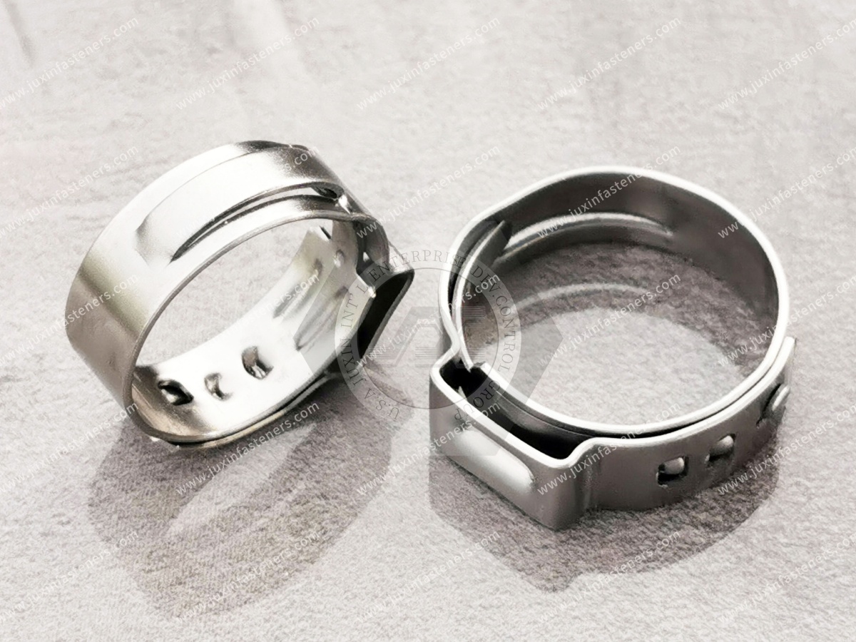
Common hose-clamping technologies include:
Perforated-band worm-drive clamps
Non-perforated or embossed-band worm-drive clamps
Ear clamps
Spring-band clamps
Constant-tension clamps
T-bolt clamps
Each architecture applies and maintains clamping action differently.
They should not be treated as interchangeable simply because they fit around the same hose.
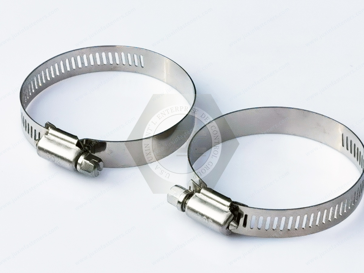
A perforated worm-drive hose clamp uses a screw that engages openings formed in the band.
Turning the screw moves the band through the housing and changes the clamp diameter.
These clamps are commonly selected where engineers require:
Adjustable diameter
Straightforward installation
Serviceability
Removal and reinstallation where appropriate
Broad size availability
They are frequently associated with the commercial term American-style hose clamp.
However, the regional name alone does not define the complete specification.
The functional sequence is:
screw rotation → band engagement → band movement → diameter reduction → hose compression
Performance depends on:
Screw geometry
Band geometry
Housing
Band width
Material
Clamp range
Hose
Fitting
The presence of perforations alone does not determine the performance of the complete clamp.
One important characteristic of a worm-drive clamp is its adjustable diameter range.
This can be useful for:
Service applications
Maintenance
Assembly variation within the intended range
Multiple hose sizes where appropriately specified
However, a wide adjustment range should not be used to compensate for an incorrectly sized hose or fitting.
The hose-to-fitting interface must still be compatible.
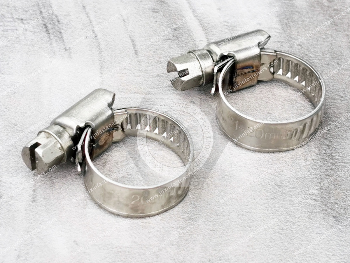
Another worm-drive architecture uses embossed or formed band features instead of fully perforated openings.
These clamps are frequently associated with the commercial description German-style hose clamp.
The non-perforated band provides a different hose-contact surface from a fully perforated design.
Depending on the specific design and application, this architecture may be considered where hose surface interaction is important.
But “German style” should not be interpreted as a universal performance specification.
This is a useful engineering comparison.
The screw engages openings through the band.
The screw engages formed features without the same fully open perforation structure.
The correct choice depends on:
Hose material
Hose surface
Clamp geometry
Required adjustment range
Installation requirements
Customer specification
Neither should automatically be described as universally stronger or better.
The edges of the clamp band contact or sit close to the hose surface.
Depending on hose material and installation condition, band edge geometry can influence local hose stress.
This can be particularly relevant for:
Soft hoses
Silicone hoses
Thin-wall hoses
Applications sensitive to surface damage
When qualifying a second source, compare band edge design as well as width and thickness.
“British-style hose clamp” is another commercial term encountered in the global market.
As with American-style and German-style descriptions, the name can help identify a general product family but should not be treated as a complete engineering specification.
Different suppliers can use regional labels differently.
For OEM sourcing, specify the actual:
Clamp range
Band width
Band construction
Screw
Housing
Material
Finish
This avoids ambiguity across suppliers and regions.
Suppose an RFQ says only:
“German hose clamp, 30–50 mm.”
Several technical questions remain unanswered:
What band width?
What band thickness?
What material?
What screw material?
What housing material?
What band profile?
What finish?
What hose is being clamped?
What fitting is underneath?
What installation requirements apply?
For repeatable B2B sourcing, regional terminology should be supplemented by technical specifications.
Ear clamps use one or more formed ears that are mechanically compressed during installation.
They are also commonly described as:
Pinch clamps
Single-ear clamps
Double-ear clamps, depending on design
Unlike a worm-drive clamp, an ear clamp does not normally use a screw for diameter adjustment during installation.
Instead, a suitable installation tool deforms the ear according to the clamp design.
The basic installation sequence is:
position clamp → compress ear with appropriate tool → reduce clamp diameter → establish hose compression
Because installation involves permanent deformation of the ear, service behavior differs from a screw-adjustable worm-drive clamp.
This distinction is important when considering maintenance and replacement.
Ear clamps should be installed using tooling appropriate for the specific clamp design.
Tooling and installation geometry can affect:
Ear deformation
Clamp closure
Alignment
Hose compression
Assembly repeatability
For production programs, the installation process should be defined and validated.
Avoid assuming that any general-purpose pliers will produce the required result.
An ear clamp that is permanently deformed during installation should not automatically be considered reusable.
If an application requires routine removal and reinstallation, this should be considered during clamp selection.
Serviceability is therefore one of the major differences between ear clamps and adjustable worm-drive clamps.
Depending on the design and application, ear clamps can offer:
Compact installation
Defined mechanical closure method
No protruding adjustment screw
Production-friendly assembly when tooling is controlled
Their suitability still depends on the hose, fitting, environment, and customer requirements.
No hose clamp should be described as universally leak-proof.
Connection integrity depends on the complete assembly:
hose + fitting + clamp + installation + fluid + pressure + temperature
An ear clamp can be appropriate for many applications, but the complete connection must be validated under actual service conditions.
Spring-band clamps use the elastic behavior of the clamp material to apply clamping action over a designed operating range.
Their working principle differs from both worm-drive and ear clamps.
They can be considered where the hose connection experiences dimensional changes caused by factors such as:
Temperature
Hose relaxation
Material behavior
The clamp architecture should be matched to the intended hose and fitting.
The major difference is how clamping action is established and maintained.
The installer mechanically adjusts the diameter using a screw.
Elastic spring behavior provides the clamping action within the clamp's designed range.
This difference can matter in thermally cycled hose systems.
Neither technology is universally preferable.
Constant-tension clamp designs are intended to accommodate dimensional changes within their designed operating range.
This can be relevant where:
Hose material relaxes
Temperature varies significantly
Interface dimensions change during service
The exact behavior depends on the specific clamp architecture.
“Constant tension” should not be interpreted as literally identical clamping force under every possible operating condition.
A conventional worm-drive clamp is adjusted to an installed condition.
If the hose changes dimension significantly afterward, the joint condition can change.
A constant-tension design uses an additional mechanical principle intended to respond to dimensional change.
For thermally demanding applications, engineers may compare these technologies during design validation.
A T-bolt clamp uses a different tightening architecture from a conventional worm-drive clamp.
Typical components can include:
Band
T-bolt
Nut
Bridge or related structural components, depending on design
T-bolt clamps are commonly considered for applications with different size, load, or mechanical requirements from general-purpose worm-drive clamps.
However, a T-bolt clamp should not automatically be described as “higher performance” without defining the application.
A useful comparison includes:
Worm-drive clamps use screw-to-band engagement.
T-bolt clamps use a bolt-and-nut tightening architecture.
The band and load-transfer geometry differ.
Tool access and tightening processes differ.
Selection depends on hose size, fitting geometry, operating conditions, and customer requirements.
The appropriate technology should be chosen from the joint requirements, not appearance.
A practical selection process starts with the assembly rather than the clamp catalog.
Identify:
Hose ID
Installed OD
Wall thickness
Material
Reinforcement
Compression behavior
Review:
Fitting OD
Bead or barb geometry
Engagement length
Surface
Material
Wall thickness where relevant
Consider:
Fluid or media
Temperature
Pressure requirements
Vibration
Corrosion
Outdoor exposure
Thermal cycling
Ask:
Is repeated removal required?
Is production tooling available?
Is screw access available?
Is installation space limited?
Is automated or controlled assembly required?
Then evaluate:
Worm-drive
Ear clamp
Spring-band
Constant-tension
T-bolt
Other application-specific technologies
The final selection should be validated under the actual service conditions where required.
A worm-drive clamp may be considered when the application benefits from:
Diameter adjustability
Screw installation
Service access
Removal capability
Broad availability
But the actual clamp range and hose compatibility must still be defined.
An ear clamp may be considered where:
Compact geometry is useful
Production assembly can use dedicated tooling
Screw adjustment is not required
Routine clamp reuse is not required
The actual installation process should be validated.
These technologies may deserve consideration where:
Temperature cycling is significant
Hose dimensions change in service
Hose relaxation is an engineering concern
The decision should be based on the actual hose and fitting system.
T-bolt clamps may be considered where the application geometry and mechanical requirements favor that architecture.
Relevant factors can include:
Hose size
Available space
Band construction
Required installation method
Joint requirements
Do not select them simply because they appear heavier than worm-drive clamps.
Automotive hose systems can experience:
Vibration
Temperature cycling
Fluid exposure
Tight packaging
Production assembly requirements
Different clamp technologies can therefore appear in different vehicle systems.
Potential applications include suitable:
Cooling connections
Air-intake connections
Heater-related hose assemblies
Auxiliary fluid circuits
Thermal-management equipment
Clamp selection should follow the OEM's specific engineering requirements.
EV thermal-management systems can contain:
Coolant hoses
Pumps
Heat exchangers
Battery thermal components
Power-electronics cooling components
Depending on system architecture, different clamp technologies may be considered.
Selection should account for:
Coolant compatibility
Temperature
Vibration
Hose behavior
Fitting geometry
Leak-control requirements
Assembly process
The complete coolant connection should be validated rather than relying on a generic clamp performance claim.
HVAC and industrial thermal-management systems can use flexible hoses around:
Pumps
Heat exchangers
Cooling loops
Chillers
Auxiliary thermal equipment
Worm-drive, spring-based, or other clamp technologies may be used depending on the equipment architecture.
For equipment manufacturers, hose behavior under temperature changes is an important selection factor.
Data center and AI/HPC cooling infrastructure increasingly includes liquid-cooling equipment.
Depending on equipment architecture, flexible connections may occur around:
Cooling distribution equipment
Pumps
Heat exchangers
Auxiliary coolant circuits
Clamp selection should consider:
Hose construction
Fitting design
Coolant
Temperature
Pressure requirements
Installation
Serviceability
Leak-control requirements
No hose clamp architecture should be assumed suitable without evaluation of the actual liquid-cooling connection.
Industrial machinery can use hose clamps in systems involving:
Cooling
Lubrication
Air handling
Fluid transfer
Pumps
Serviceability can be especially important in industrial equipment.
A worm-drive clamp may be convenient where maintenance access is required, while other clamp architectures may be selected for production-controlled connections.
Outdoor equipment can expose hose connections to:
Water
Dirt
Fertilizers
Chemicals
Vibration
Temperature variation
Material and coating selection should therefore be part of the clamp decision.
Clamp architecture alone does not determine environmental durability.
Marine-related equipment requires careful corrosion evaluation.
Consider the materials of:
Clamp band
Screw
Housing
Fitting
Adjacent components
A product described only as a “stainless hose clamp” may not define every component material.
The actual stainless grade and complete assembly should be reviewed where corrosion requirements are critical.
General-purpose hose clamps should not be automatically treated as sanitary process clamps.
Food, beverage, pharmaceutical, and biotechnology systems may use purpose-designed sanitary connection technologies.
Similarly, industrial process piping can use:
Flanged connections
Sanitary clamp systems
Grooved couplings
Quick-connect couplings
Other engineered piping connections
These are different technologies from general-purpose hose clamps.
The connection method must be selected according to the equipment and process requirements.
A buyer may request:
Automotive hose clamp
Marine hose clamp
HVAC hose clamp
These descriptions provide useful application context but do not define the component.
The supplier still needs:
Clamp type
Diameter range
Band width
Material
Hose information
Fitting information
Environment
Industry name should complement the technical specification, not replace it.
It does not.
Two suppliers can offer products described as American-style clamps with different:
Band widths
Band thicknesses
Screw designs
Housing geometry
Materials
Finishes
For second-source qualification, compare the actual parts.
A non-perforated band provides a different interface with the hose, but that does not make it universally superior.
Performance depends on:
Hose
Fitting
Clamp geometry
Installation
Service conditions
Select the architecture for the application.
Rubber, silicone, thermoplastic, and reinforced hoses can respond differently to clamp compression.
The same clamp and installation condition may not produce the same result on each hose.
Validation should use the actual production hose where possible.
Leakage can originate from:
Wrong hose size
Wrong fitting
Damaged hose
Incorrect clamp position
Hose relaxation
Incorrect clamp range
Surface contamination
Thermal cycling
Increasing torque without diagnosing the interface can damage the hose or clamp.
The clamp alone does not define the pressure capability of a hose connection.
The complete assembly determines performance:
hose + fitting + clamp + installation + fluid + temperature + operating conditions
Pressure-sensitive systems should be validated as complete assemblies.
Depending on design and customer requirements, hose clamps may use:
Carbon steel
Stainless steel
Mixed component material combinations
Where corrosion resistance matters, procurement should define which components require a specific material.
For example, requirements can separately apply to:
Band
Screw
Housing
Avoid assuming that a commercial description fully defines all three.
Depending on clamp architecture, useful drawing requirements can include:
Clamp type
Diameter range
Band width
Band thickness where controlled
Band architecture
Screw or closure geometry
Housing geometry where applicable
Component materials
Finish
Critical dimensions
Customer-specific requirements
Installation or performance requirements should be specified only where properly defined for the application.
For second-source development, do not compare clamps only by diameter.
Review:
Clamp architecture
Diameter range
Band width
Band thickness where controlled
Band profile
Screw or closure mechanism
Housing
Material
Finish
Hose interface
Fitting interface
Installation method
The replacement should be validated according to the customer's qualification process.
A drawing provides controlled dimensional and material requirements.
An approved physical sample can provide additional information about:
Form
Band geometry
Edge condition
Housing construction
Screw design
Assembly relationship
For existing production parts, providing both where available gives the supplier a stronger basis for technical review.
Provide:
Clamp type
Required diameter range
Actual hose OD
Band width
Material
Finish where applicable
Application
Quantity
Annual demand
Provide:
Hose specification
Hose ID and relevant OD
Fitting drawing or dimensions
Fluid or media
Temperature conditions
Pressure requirements
Vibration conditions
Corrosion environment
Installation requirements
Serviceability requirements
Expected production volume
The clamp architecture can then be reviewed against the actual joint.
For an existing production clamp, provide where available:
drawing + unused approved sample + existing part number + hose specification + fitting information + installed OD + material + finish + annual demand
Also identify the sourcing objective, such as:
Supply continuity
Alternative supplier qualification
Capacity expansion
Lead-time reduction
Regional sourcing
Cost review
This connects technical qualification with the procurement objective.
Related engineering and sourcing resources include:
Worm-Drive Hose Clamps
How Worm-Drive Hose Clamps Work
Hose Clamps for Reducer Connections
Stainless Steel Hose Clamps
Automotive Fasteners
HVAC Fasteners
Thermal Management Fasteners
Custom Fasteners
Second-Source Fasteners
These resources can support engineers and sourcing teams evaluating the complete assembly rather than selecting a clamp from a product name alone.
JUXIN FASTENERS supports industrial fasteners, hose clamps, and drawing-controlled components for global OEM, equipment-manufacturing, and supply-chain projects.
Technical review can begin from:
Customer drawing
Existing specification
Approved sample
Hose information
Fitting information
Material requirements
Application environment
Installation requirements
Order quantity
Annual demand
For second-source development, the objective is to match the required interface and specification rather than simply supply a clamp with a similar commercial name.
The most useful engineering question is not:
Which hose clamp type is best?
It is:
Which clamp architecture is appropriate for this hose, fitting, installation process, environment, and service requirement?
A practical engineering decision path is:
hose → fitting → installed OD → operating conditions → assembly method → service requirements → clamp architecture → material → installation → validation
For procurement and supplier-development teams:
drawing/sample → clamp type → diameter range → band/closure geometry → component materials → hose/fitting interface → annual demand → qualification requirements
If you require worm-drive hose clamps, ear clamps, T-bolt clamps, other industrial hose clamps, or second-source development for an existing OEM program, send JUXIN FASTENERS your available technical information.
For an existing production part, provide the drawing and unused approved sample where available.
For a new application, provide the hose specification, fitting information, actual hose OD, operating environment, required clamp type or application requirements, and expected volume.
For second-source development, provide the existing clamp specification, approved sample, mating hose and fitting information,
and annual demand so the proposed part can be reviewed against the actual assembly.
Email: info@juxinfasteners.com
Website: www.juxinfasteners.com
 MORE NEWS

Sep. 27, 2026

Sep. 27, 2026

Sep. 27, 2026
Contact Us
Tel.:
+86 020 8621 0320
+86 020 3121 6067
E-mail:
Technical Support:
Navigation
SEND INQUIREY