
Call Us
+86 136 6007 9809
Call Us
+86 136 6007 9809

Oct. 27, 2023
A worm-drive hose clamp looks mechanically simple: turn a screw and the metal band tightens around the hose.
But what actually happens inside the clamp?
Understanding the mechanism is important for engineers selecting a clamp, manufacturing teams defining an assembly process,
maintenance technicians diagnosing a clamp that will not tighten, and procurement teams qualifying an alternative supplier.
A conventional worm-drive hose clamp should not be confused with a worm gear and worm wheel transmission.
Instead, the basic mechanism normally consists of:
A metal band
A screw
A housing
Formed engagement features in the band
When the screw rotates, its thread engages the corresponding features in the band. This converts screw rotation into movement of the band through the housing, changing the clamp diameter.
The engineering principle is therefore:
screw rotation → screw-to-band engagement → band movement → diameter reduction → radial compression around the hose
That mechanism explains both how worm-drive clamps work and why they sometimes slip, strip, deform, or fail to tighten correctly.
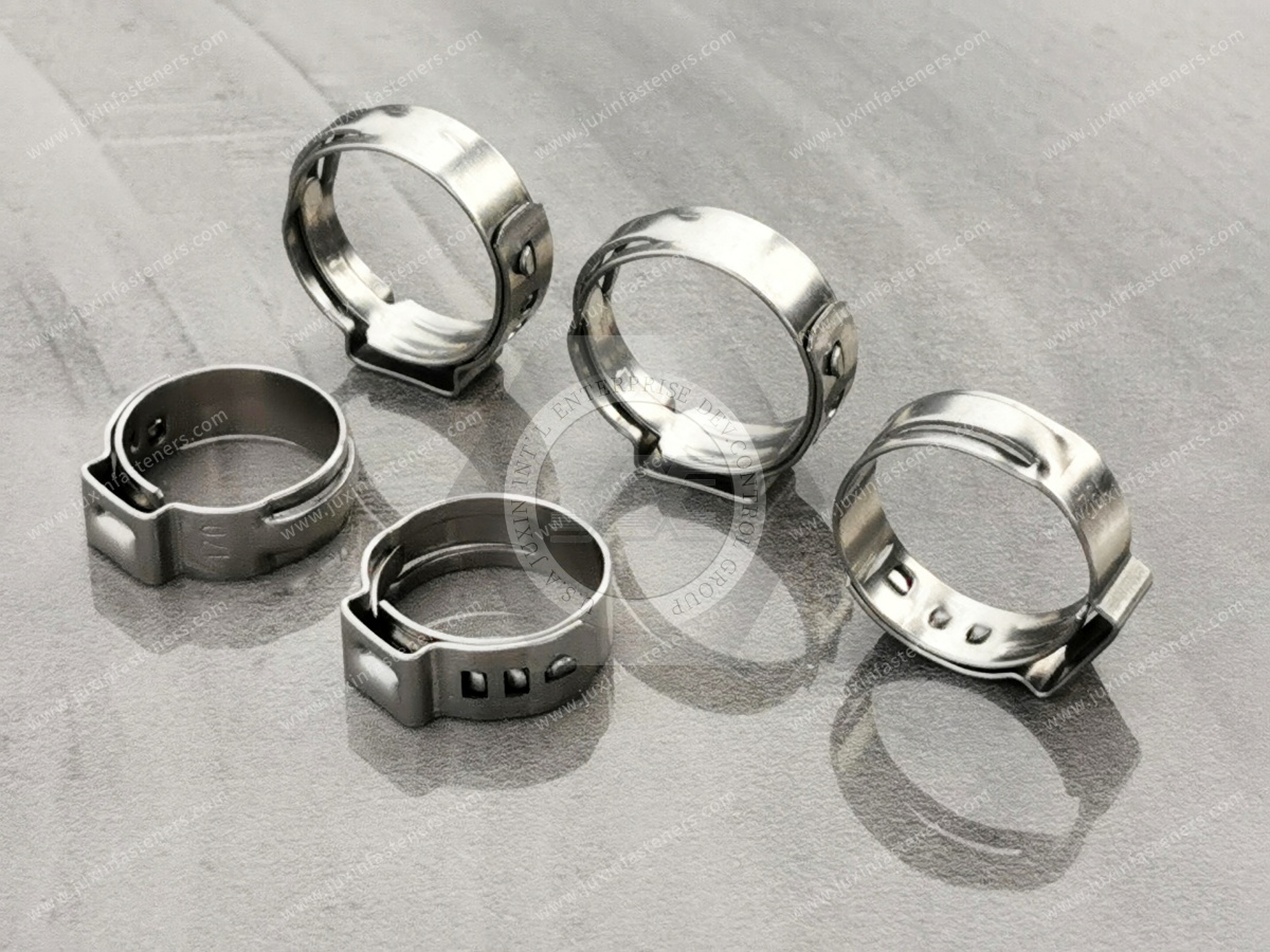
The term “worm gear hose clamp” is widely used commercially, but it can create confusion.
A traditional worm gear transmission normally involves a worm interacting with a separate worm wheel or gear.
A conventional worm-drive hose clamp does not normally contain a separate worm wheel.
Instead, the screw engages features formed directly into the clamp band.
This distinction matters because a hose clamp should not be evaluated using assumptions intended for industrial worm gearboxes, such as transmission efficiency, gear reduction, shaft loading, or worm-wheel materials.
A hose clamp is a clamping device, not a power-transmission gearbox.
Although designs vary, the basic functional components are straightforward.
The band wraps around the hose and transfers clamping action around the circumference.
Important characteristics can include:
Diameter range
Band width
Band thickness
Material
Edge geometry
Perforated or non-perforated design
The screw provides the input for tightening and loosening.
Its thread interacts with features in the band.
Relevant characteristics can include:
Thread geometry
Material
Head or drive configuration
Dimensional relationship with the band
Surface condition
The housing supports and locates the screw while guiding the band through the engagement region.
Housing geometry influences alignment between the screw and band.
Depending on clamp design, these may be:
Perforations
Slots
Embossed features
Other formed engagement geometries
These features allow screw rotation to move the band.
When the installer turns the screw in the tightening direction, the screw thread engages the band features.
As the screw rotates:
The band is drawn through the housing.
The effective loop diameter decreases.
The band contacts the hose.
Continued tightening compresses the hose against the fitting.
The hose, fitting, clamp and installation condition together establish the final joint.
The screw does not simply “lock the hose.”
It controls band movement.
The resulting connection behavior depends on the complete hose-to-fitting interface.
The clamp can only tighten correctly if the screw and band maintain suitable engagement.
This relationship depends on factors such as:
Screw thread geometry
Band feature geometry
Alignment
Material condition
Housing geometry
Manufacturing tolerances
Clamp operating diameter
If these features are incompatible or damaged, the screw can rotate without producing the intended band movement.
This is why two clamps that appear visually similar may not behave identically.
In a perforated-band design, openings are formed through the band.
The screw engages these openings and moves the band as it rotates.
This architecture is widely used in general-purpose worm-drive clamp families.
Engineering considerations include:
Perforation geometry
Band strength
Screw engagement
Hose contact
Band edge condition
Installed diameter
Perforated construction should not automatically be described as better or worse than other designs without considering the application.
Some worm-drive clamps use embossed or formed engagement features instead of fully perforated openings.
This creates a different band structure and hose-contact surface.
Depending on the application, engineers may compare perforated and non-perforated designs based on:
Hose material
Clamp range
Required band width
Installation requirements
Application environment
Customer specification
The commercial labels “American type,” “German type,” or similar descriptions should not replace the actual technical specification.
Before contact, much of the screw rotation is used to reduce clamp diameter.
After the band contacts the hose, continued tightening increasingly affects the hose-to-fitting interface.
At this stage, several components deform to some degree:
Hose
Clamp band
Housing
Screw engagement
Potentially the fitting, depending on its construction
This means tightening behavior cannot be understood from the clamp alone.
A soft hose over a rigid fitting behaves differently from a reinforced hose over a thin-wall fitting.
Once the hose is compressed against the fitting, additional input torque can be consumed by several mechanisms:
Friction
Hose deformation
Band deformation
Housing deformation
Screw-to-band interaction
Fitting deformation
Therefore:
input torque ≠ universal clamp force
There is no single conversion from screw torque to useful hose clamping force that applies to every worm-drive clamp and hose assembly.
Installation requirements should be based on the specific clamp and joint design.
Engineers sometimes search for a single recommended torque for a hose clamp size.
But the correct installation condition depends on:
Clamp design
Clamp size
Band width
Screw geometry
Hose material
Hose wall thickness
Fitting geometry
Surface condition
Operating environment
A torque appropriate for one assembly may damage another.
For production assemblies, use a validated installation specification where required.
The housing is more than a cover around the screw.
It helps:
Position the screw
Guide the band
Maintain engagement geometry
Transfer reaction forces within the clamp
If the housing deforms excessively, the screw can lose effective alignment with the band.
This can contribute to slipping or failure to tighten.
Housing geometry is therefore an important part of second-source comparison.
Band width influences how the clamp contacts the hose.
A wider band distributes interaction over a broader axial region, while a narrower band creates a different pressure distribution.
But wider does not automatically mean better.
The appropriate band width depends on:
Hose geometry
Fitting engagement length
Available installation space
Hose material
Clamp design
The band should fit within the intended clamping region.
It is tempting to compare two clamps by measuring band thickness and selecting the thicker one.
That is incomplete.
Clamp behavior depends on the system of:
band + screw + housing + engagement geometry + material + installed diameter
A thicker band with unsuitable engagement geometry is not automatically a better clamp.
For supplier qualification, compare the complete design.
Every adjustable worm-drive clamp has an intended operating range.
As the clamp diameter changes, the relative position of the band and housing also changes.
Operating near an unsuitable extreme can affect:
Band overlap
Housing position
Installation access
Circularity
Engagement condition
The selected clamp should match the actual installed hose OD rather than merely being physically capable of fitting around it.
“Clamp slipping” can describe several different failure modes.
Possible causes include:
Damaged band engagement features
Damaged screw threads
Poor screw-to-band alignment
Housing deformation
Clamp operating outside its intended range
Excessive tightening
Manufacturing variation
Incorrect replacement components
The failure should be diagnosed before simply applying more torque.
This is one of the most useful diagnostic questions.
If the screw rotates but the band no longer moves correctly, inspect:
Look for damaged or worn thread features.
Inspect perforations, slots, or embossed engagement features for deformation.
Check whether the housing has opened, distorted, or lost alignment.
Confirm that the clamp is being used within an appropriate diameter range.
Determine whether the clamp was previously over-tightened or damaged.
A clamp with damaged engagement should generally not be relied upon simply because the screw can still rotate.
A “stripped” clamp typically means that the screw and band can no longer maintain the intended engagement.
Potential contributors include:
Excessive tightening
Damaged screw threads
Deformed band features
Housing distortion
Material damage
Incorrect screw/band relationship
The failure may be progressive.
A clamp can begin slipping before it becomes completely unable to tighten.
Applying additional torque after the required assembly condition has been reached can overload the clamp components.
Possible effects include:
Band feature deformation
Screw damage
Housing deformation
Hose cutting
Hose extrusion
Fitting deformation
For this reason, “tighten as much as possible” is not an appropriate assembly instruction.
Insufficient tightening can leave inadequate compression between the hose and fitting.
Depending on the application, symptoms can include:
Hose movement
Leakage
Reduced retention
Clamp migration
However, these symptoms can also result from incorrect hose or fitting geometry.
Diagnosis should consider the complete interface.
A mechanically tight clamp does not guarantee a sealed hose connection.
Possible reasons include:
Hose ID incompatible with fitting OD
Damaged hose
Damaged fitting
Incorrect clamp position
Hose wrinkles
Surface contamination
Incorrect fitting geometry
Thermal cycling
Hose relaxation
This leads to an important engineering rule:
Clamp tightness and joint sealing are related, but they are not the same thing.
The clamp acts on the hose, so hose properties matter.
Depending on construction, a hose may be:
Soft and highly compressible
Reinforced
Relatively stiff
Sensitive to localized pressure
Subject to creep or relaxation
A clamp that performs well on one hose material may require different installation conditions on another.
Validation should use the actual production hose where possible.
Some hose materials can relax over time after initial compression.
Temperature can further influence this behavior.
As the hose changes, the joint condition can also change.
Factors include:
Hose material
Reinforcement
Temperature
Initial compression
Fitting geometry
Time
A conventional worm-drive clamp should therefore not automatically be described as providing constant clamping force under every service condition.
A hose connection can contain materials with different thermal behavior:
Metal clamp
Metal or polymer fitting
Elastomeric or thermoplastic hose
Heating and cooling can alter their relative dimensions and mechanical properties.
For applications with significant thermal cycling, engineers should evaluate whether a conventional worm-drive clamp or another clamp architecture is more appropriate.
These technologies solve the clamping problem differently.
The installer mechanically adjusts the clamp to the required installed condition.
The clamp incorporates a mechanism intended to accommodate dimensional change within its designed operating range.
Where thermal cycling or hose relaxation is important, engineers may compare the two approaches.
They should not be treated as interchangeable technologies without validation.
A spring-band clamp relies on elastic spring behavior rather than a screw-driven band adjustment mechanism.
Spring-band clamps can be suitable for certain production hose assemblies.
The choice between them depends on:
Hose material
Fitting design
Temperature
Assembly process
Serviceability
Application requirements
T-bolt clamps use a different band and tightening architecture.
They may be considered for particular hose sizes or mechanical requirements.
However, the larger appearance of a T-bolt clamp does not make it universally superior.
The complete hose connection should determine the clamp technology.
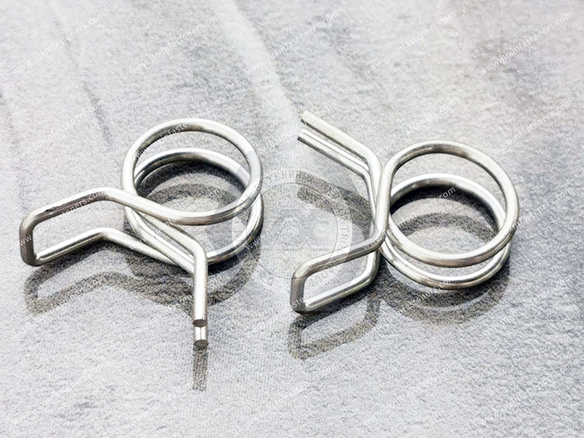
Suppose procurement needs a second source for an existing worm-drive clamp.
Matching only:
minimum diameter + maximum diameter
is not enough.
The replacement can differ in:
Band width
Band thickness
Perforation or embossing geometry
Screw
Housing
Material
Finish
Band edge
Installed geometry
A dimensional fit does not automatically establish functional equivalence.
For an existing OEM clamp, compare the original and proposed source in several areas.
Review:
Clamp range
Band width
Band thickness where controlled
Housing dimensions
Screw dimensions
Compare:
Band feature geometry
Screw engagement
Housing alignment
Define where required:
Band material
Housing material
Screw material
Confirm coating or surface requirements where applicable.
Evaluate with the actual:
Hose
Fitting
Installed OD
Clamp position
Consider:
Temperature
Vibration
Corrosion
Fluid environment
Service requirements
The customer's qualification process should determine final approval.
A drawing may define critical dimensions, but a physical approved sample can reveal additional construction details such as:
Housing form
Band feature geometry
Screw design
Edge condition
Assembly relationship
For second-source development, providing both a drawing and an unused approved sample can reduce ambiguity.
Worm-drive hose clamps can be used in suitable automotive and vehicle-related assemblies involving:
Cooling hoses
Air-handling connections
Auxiliary fluid connections
Serviceable hose assemblies
Clamp selection should follow the vehicle manufacturer's hose, fitting, environment, and assembly requirements.
Not every automotive hose joint uses or should use a worm-drive clamp.
HVAC and industrial thermal-management equipment can contain hose connections around:
Pumps
Heat exchangers
Cooling loops
Auxiliary fluid systems
For these systems, engineers should consider:
Hose material
Fitting geometry
Temperature
Fluid
Vibration
Corrosion
Serviceability
The clamp mechanism should be selected as part of the complete connection.
Liquid-cooling equipment for data centers and AI/HPC infrastructure can include flexible hose connections in certain system architectures.
Potential equipment can include:
Cooling distribution equipment
Pump assemblies
Heat exchangers
Auxiliary cooling circuits
Where worm-drive clamps are considered, engineers should evaluate the complete interface, including:
Coolant
Hose
Fitting
Pressure
Temperature
Installation
Leak-control requirements
The clamp should only be used where appropriate for the specific equipment design and validated service conditions.
Worm-drive clamps can be used in suitable machinery connections involving:
Cooling
Lubrication
Air handling
Fluid transfer
Maintenance-accessible hoses
For equipment manufacturers, consistent clamp geometry and controlled installation can improve assembly repeatability.
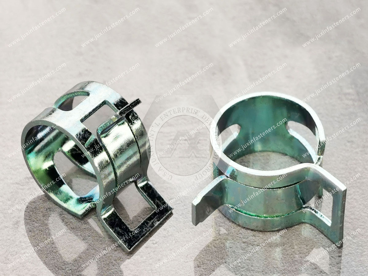
Outdoor equipment can expose clamps to:
Water
Dirt
Chemicals
Vibration
Temperature changes
The required clamp material and finish should be selected according to the environment.
Do not assume that every stainless or plated clamp provides the same corrosion performance.
Depending on the product design and customer specification, worm-drive clamps can use carbon steel, stainless steel, or combinations of materials.
Procurement should define whether requirements apply to:
Band
Housing
Screw
This is important because a commercial description such as “stainless steel hose clamp” may not by itself define the material of every component.
For a drawing-controlled worm-drive clamp, consider defining:
Clamp diameter range
Band width
Band thickness where required
Band architecture
Housing geometry
Screw requirements
Band material
Housing material
Screw material
Finish
Critical dimensions
Customer-specific requirements
Avoid specifying universal torque, pressure, or sealing claims unless they are tied to a defined assembly and validated requirement.
For standard sourcing, provide:
Required clamp range
Actual hose OD
Band width
Material
Finish where applicable
Application
Quantity
Annual demand
If replacing an existing clamp, include its part number or sample where available.
For custom or drawing-controlled clamps, provide:
2D drawing
Clamp range
Band geometry
Band width
Component materials
Finish
Hose specification
Fitting information
Application environment
Quantity
Annual volume
Any special performance requirements should be clearly defined.
For an existing production part, provide where available:
drawing + unused approved sample + hose specification + fitting information + installed OD + material requirements + finish + annual demand
Also identify the commercial objective, such as:
Supply continuity
Alternative supplier qualification
Capacity expansion
Lead-time reduction
Regional sourcing
Cost review
This allows technical and sourcing requirements to be reviewed together.
Related engineering and sourcing resources include:
Worm-Drive Hose Clamps
Hose Clamps for Reducer Connections
Stainless Steel Hose Clamps
Automotive Fasteners
HVAC Fasteners
Thermal Management Fasteners
Custom Fasteners
Custom Stamped Components
Second-Source Fasteners
These resources can support engineers and procurement teams working on complete OEM assemblies rather than isolated fastener selection.
JUXIN FASTENERS supports industrial fasteners, hose clamps, and drawing-controlled components for global OEM and equipment-manufacturing projects.
Technical review can begin from:
Customer drawing
Existing clamp specification
Approved sample
Hose information
Fitting information
Material requirements
Application environment
Expected order quantity
Annual demand
For second-source programs, the objective is not simply to find a clamp that looks similar.
The proposed component should be reviewed against the dimensional interface, screw-to-band architecture, material requirements, assembly conditions, and customer qualification requirements.
The essential operating principle of a worm-drive hose clamp is:
screw rotation → engagement with the band → controlled band movement → diameter reduction → compression of the hose around the fitting.
For engineers, the decision path should be:
hose + fitting → installed OD → clamp architecture → band and screw engagement → material → installation condition → service environment → validation.
For procurement and supplier-development teams, the sourcing path should be:
drawing/sample → clamp range → band geometry → screw and housing → component materials → hose/fitting interface → annual demand → qualification requirements.
If you require worm-drive hose clamps, custom clamps, replacement clamps, or second-source development for an existing OEM program, send JUXIN FASTENERS your available technical information.
For an existing part, provide the drawing and unused approved sample where available.
For a new application, provide the hose OD, hose specification, fitting information, required clamp range, material, environment, and expected volume.
For second-source development, provide the existing clamp specification, approved sample, mating hose and fitting information,
and annual demand so the proposed part can be reviewed against the actual assembly.
Email: info@juxinfasteners.com
Website: www.juxinfasteners.com
Previous: Hose Clamp Types: Selection Guide
Next: Hose Clamps for Reducers
 MORE NEWS

Sep. 27, 2026

Sep. 27, 2026

Sep. 27, 2026
Contact Us
Tel.:
+86 020 8621 0320
+86 020 3121 6067
E-mail:
Technical Support:
Navigation
SEND INQUIREY