
Call Us
+86 136 6007 9809
Call Us
+86 136 6007 9809

Oct. 27, 2023
How do you securely connect hoses or tubes with different diameters?
A common assumption is that a sufficiently adjustable hose clamp can compensate for the size difference.
In many engineered assemblies, that is the wrong starting point.
A hose clamp provides radial clamping around a hose. It does not normally create the required diameter transition by itself.
Where two parts have different connection diameters, the assembly may require an appropriately designed:
Reducer fitting
Stepped hose fitting
Reducing hose
Molded transition hose
Adapter
Other engineered transition interface
The clamps then secure the hose at the respective connection points.
For engineers and procurement teams, the complete system should therefore be evaluated as:
large-side interface → transition component → small-side interface → correctly sized clamps
Understanding this distinction can prevent leakage, hose damage, poor retention, and incorrect clamp selection.
Usually, the first question should not be whether the clamp has enough adjustment range.
The more important question is:
Is the hose-to-fitting geometry designed to accommodate the diameter difference?
A worm-drive clamp can adjust around a range of hose outside diameters, but excessive compression should not be used as a substitute for proper interface geometry.
If a hose is significantly larger than the fitting underneath it, tightening the clamp further can create:
Hose folding
Wrinkling
Uneven compression
Localized stress
Poor circumferential contact
Hose damage
Unreliable sealing
The appropriate solution is generally to design the diameter transition first and then select the clamp for each interface.
This distinction is fundamental.
The clamp applies radial compression around the hose at a defined connection.
The reducer provides the geometric transition between different connection diameters.
The two components perform different functions.
A well-designed transition assembly may therefore look like:
large hose + clamp → reducer → small hose + clamp
or:
reducing hose + appropriately sized clamp at each end
The correct architecture depends on the equipment design.
A reducer hose connection transitions between interfaces with different diameters.
Depending on the system, the transition may be created by:
Rigid reducer fitting
Stepped fitting
Molded reducing hose
Flexible reducer
Custom adapter
Each end is designed for a specific hose or tube interface.
The clamp is then selected for the assembled outside diameter at that location.
Not necessarily.
If the two ends have different assembled outside diameters, they may require different clamp sizes.
They can also require different:
Band widths
Clamp constructions
Materials
Installation conditions
For example:
Side A: larger hose OD → Clamp Range A
Side B: smaller hose OD → Clamp Range B
The fact that both clamps belong to the same assembly does not mean they should have identical dimensions.
For each side of a reducer connection, determine the actual assembled hose outside diameter.
Do not select the clamp only from:
Nominal pipe size
Hose inside diameter
Reducer name
Clamp maximum diameter
The installed hose OD can depend on:
Hose ID
Wall thickness
Reinforcement
Fitting OD
Hose tolerance
Compression condition
The selected clamp range should correspond to the real assembly.
A hose described by its nominal inside diameter does not tell the buyer its exact outside diameter.
Two hoses with the same nominal ID can have different wall thicknesses and therefore different ODs.
For clamp sourcing, this matters because the clamp contacts the outside of the hose.
A useful RFQ should therefore identify both the hose specification and the relevant outside diameter.
Consider a hose that is substantially larger than the fitting underneath it.
The installer may attempt to tighten a worm-drive clamp until the hose collapses onto the fitting.
The clamp may become tight, but the joint can still have poor geometry.
The hose can deform unevenly around the circumference.
This illustrates an important engineering principle:
Clamp tightness does not prove interface compatibility.
A properly designed hose-to-fitting relationship should exist before the clamp is tightened.
When an oversized hose is compressed too far, the hose wall may form folds or wrinkles.
This can create nonuniform contact around the fitting.
Potential consequences include:
Local leakage paths
Uneven clamp loading
Hose damage
Reduced retention
Poor assembly repeatability
Increasing tightening torque may make the problem worse.
The solution should address the interface geometry.
A reducer fitting is not defined only by its two diameters.
Relevant features can include:
Large-side OD
Small-side OD
Transition geometry
Bead or barb geometry
Engagement length
Surface condition
Wall thickness
Material
The hose and clamp should be selected to work with these features.
A fitting can use different retention architectures.
A barbed fitting introduces geometric features intended to interact with the hose.
A smooth fitting relies on a different interface condition.
The appropriate clamp and installation process can therefore differ.
Do not assume that the same clamp setup will behave identically on a smooth fitting and a barbed fitting.
Some hose fittings include a bead near the end of the connection.
Depending on the design, the bead can contribute to hose retention and help define the intended clamping region.
Clamp position relative to the bead should follow the engineering design.
Placing the clamp at an arbitrary location can change the connection behavior.
Each clamp should be positioned over the intended hose-to-fitting engagement region.
The clamp should not be placed:
Beyond the fitting engagement area
On an unintended transition
Partially off the fitting
Where it interferes with adjacent geometry
The correct location depends on the specific fitting and hose design.
A reducer fitting may have limited straight engagement length on one or both ends.
This means band width must be considered together with the fitting geometry.
A clamp that is too wide may extend beyond the intended clamping region.
A narrower clamp may fit the available envelope but creates a different contact condition.
The clamp should therefore be selected as part of the complete interface.
Hose wall thickness influences:
Outside diameter
Compression behavior
Local deformation
Clamp selection
Two hoses with the same ID but different wall thicknesses may require different clamps.
This is particularly important when replacing a hose specification while keeping the same fitting.
The existing clamp should not automatically be assumed to remain suitable.
Different hose materials respond differently to clamping.
Potential constructions include:
Rubber hose
Silicone hose
Thermoplastic hose
Reinforced hose
Multi-layer hose
Material behavior can affect:
Compression
Relaxation
Surface damage
Temperature response
The actual hose should therefore be included in connection validation.
A flexible hose may appear capable of accommodating a large dimensional mismatch.
But flexibility alone does not create a reliable engineered interface.
Excessive deformation can produce:
Folds
Nonuniform compression
Wall thinning
Local stress
The transition geometry should carry the diameter change intentionally.
If the hose, fitting, and clamp are dimensionally incompatible, additional tightening torque is not an engineering solution.
Over-tightening can damage:
Hose
Clamp band
Screw engagement
Housing
Thin-wall fitting
The appropriate sequence is:
verify interface geometry → verify clamp range → establish installation requirement
not:
tighten until leakage stops.
When a reducer hose connection leaks, inspect the complete system.
Potential causes include:
Incorrect reducer diameter
Wrong hose size
Damaged hose
Poor fitting surface
Clamp outside its intended range
Incorrect clamp position
Excessive tightening
Insufficient tightening
Hose relaxation
Thermal cycling
Chemical degradation
Changing clamp suppliers without identifying the failure mechanism may not solve the problem.
A clamp alone should not be given a universal system pressure rating.
Pressure capability depends on the complete connection:
fluid + pressure + temperature + hose + fitting + clamp + installation
The reducer interface can introduce additional geometry that also requires evaluation.
For pressure-sensitive applications, the complete assembly should be validated under the intended operating conditions.
Different components in the joint can respond differently to temperature.
The system can contain:
Metal fitting
Polymer or rubber hose
Metal clamp
These materials have different thermal and mechanical behavior.
Temperature cycling can therefore change contact conditions.
The actual hose connection should be evaluated for its expected thermal environment.
Clamp material should be selected according to the service environment.
Depending on the application, engineers may consider carbon steel with a suitable finish or stainless steel.
However, the clamp is only one metal component.
Also consider:
Reducer material
Pipe material
Moisture
Chemicals
Chlorides
Dissimilar-metal contact
For corrosive environments, define the complete material combination.
Even if the clamp is stainless steel, other components can still corrode.
The hose connection may contain:
Stainless clamp
Carbon steel fitting
Aluminum fitting
Other metallic components
Environmental exposure and material interaction should be evaluated at system level.
Avoid treating one stainless component as proof that the complete joint is corrosion-proof.
Worm-drive clamps can be useful where:
Adjustable diameter is required
The hose and fitting geometry are compatible
Installation access permits screw tightening
The service environment suits the clamp architecture
The required clamp range should be selected independently for each side of the reducer where diameters differ.
Some hose systems experience dimensional changes due to:
Temperature cycling
Hose relaxation
Material behavior
Where maintaining clamping action through such changes is important, engineers may evaluate constant-tension clamp technologies.
This is a different mechanical architecture from a conventional worm-drive clamp.
Selection should follow the application requirements.
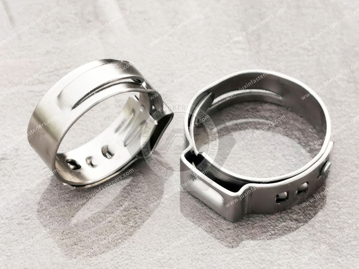
Spring-band clamps use elastic spring behavior over a designed operating range.
They may be considered for certain hose systems where:
Production assembly requirements
Thermal cycling
Hose behavior
Service requirements
favor that technology.
They should not be treated as equivalent to worm-drive clamps simply because both secure hoses.
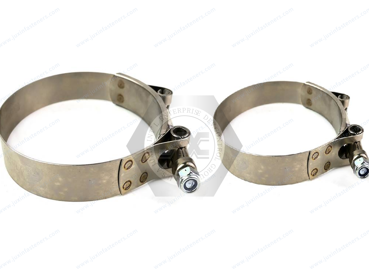
T-bolt clamps use a different band and tightening architecture.
They may be considered for particular hose sizes or mechanical requirements.
The correct selection depends on the complete connection and should not be based on the assumption that a larger clamp is automatically a higher-performance solution.
Automotive and vehicle systems can contain hoses and fittings with different diameters in suitable:
Cooling circuits
Air-handling systems
Auxiliary fluid systems
Thermal-management assemblies
Depending on the architecture, a molded reducing hose, adapter, or stepped fitting may provide the diameter transition.
The clamps should then be selected for the actual interfaces.
Production automotive applications may use different clamp technologies according to OEM engineering requirements.
EV thermal-management systems can include multiple hose and coolant connection sizes.
Where flexible hoses are used, engineers may need transitions between:
Pumps
Heat exchangers
Coolant lines
Auxiliary thermal components
The appropriate transition component and clamp technology depend on the specific system.
For coolant-related assemblies, connection integrity should be validated according to the vehicle or equipment manufacturer's requirements.

HVAC and thermal-management equipment may require diameter transitions between:
Pumps
Flexible hoses
Heat exchangers
Cooling units
Auxiliary fluid equipment
A reducer can provide the geometric transition while correctly sized clamps secure each hose interface.
For equipment manufacturers, defining both ends of the connection improves sourcing accuracy.
Liquid-cooling infrastructure for data centers and AI/HPC equipment can contain hoses, pumps, heat exchangers, distribution equipment, and other fluid-system components.
Where different connection sizes occur, an engineered transition may be required.
Depending on the equipment architecture, this can involve:
Reducer fittings
Reducing hoses
Custom adapters
Other connection technologies
If hose clamps are used, their suitability should be validated against the actual hose, fitting, coolant, temperature, pressure, and equipment requirements.
A hose clamp should not be treated as a substitute for a properly engineered reducer interface.
Industrial machinery can require hose diameter transitions in:
Cooling circuits
Lubrication systems
Pneumatic-related assemblies where appropriate
Pump systems
Process equipment
Maintenance teams should avoid forcing an available hose onto an incompatible fitting simply because an adjustable clamp can be tightened around it.
The correct interface should be defined first.
Agricultural equipment can contain hose connections exposed to:
Vibration
Dirt
Water
Chemicals
Temperature changes
Reducer connections should consider both mechanical fit and environmental exposure.
Clamp material and finish should be selected accordingly.
The term “pipe clamp” can describe many different products.
A worm-drive hose clamp should not be confused with:
Structural pipe support clamps
Flange connections
Sanitary clamp connections
Grooved pipe couplings
High-pressure pipeline connectors
These technologies use different connection principles.
For process, chemical, pharmaceutical, or high-pressure systems, the connection technology should be selected according to the applicable piping design and engineering requirements.
A worm-drive hose clamp should not automatically be specified simply because two pipes or hoses need to be connected.
Food, beverage, pharmaceutical, and biotechnology equipment can use sanitary clamp connections.
These are not the same as worm-drive hose clamps.
A sanitary clamp connection typically relies on a purpose-designed ferrule, gasket, and clamp system.
Do not describe a general-purpose hose clamp as an interchangeable sanitary process connection.
A flange connection joins mating flanges using the specified bolting and sealing system.
This is fundamentally different from a hose clamp securing a flexible hose over a fitting.
The original terms should not be combined into one product category.
Quick-connect couplings use their own locking and sealing architectures.
They can be selected where rapid connection and disconnection are required.
A quick coupling is not a subtype of worm-drive hose clamp.
Separating these technologies helps engineers and procurement teams select the correct component family.
Symptoms can include:
Heavy wrinkling
Uneven compression
Persistent leakage
Excessive tightening required
Engineering response:
Verify the hose-to-fitting size relationship and consider a proper reducer or compatible hose rather than increasing clamp torque.
A clamp that is too large may operate near or beyond its intended adjustment range.
Possible results include:
Poor band geometry
Installation difficulty
Inadequate tightening
Housing interference
Select a clamp range appropriate to the actual assembled OD.
A clamp that is too small may:
Not fit over the assembled hose
Operate outside its intended range
Be difficult to install
Create incorrect band engagement
Do not force an undersized clamp onto the assembly.
If the large and small sides have significantly different ODs, one clamp range may not be appropriate for both.
Specify each interface independently:
large side → actual OD → Clamp A
small side → actual OD → Clamp B
This simple step can improve assembly consistency.
A maintenance team may replace a hose with another product having the same nominal ID.
But the new hose can have a different wall thickness.
The result is a different OD.
Before reusing the existing clamp specification, verify that the new assembled OD remains within the appropriate range.
Use the following sequence.
Identify:
Large-side fitting OD
Small-side fitting OD
Hose specifications
Available installation space
Determine whether the system needs:
Rigid reducer
Stepped fitting
Reducing hose
Custom adapter
Another engineered connection
Do not rely only on nominal hose ID.
Depending on the application, consider:
Worm-drive clamp
Constant-tension clamp
Spring-band clamp
T-bolt clamp
Another specified technology
Treat both ends independently.
Consider:
Corrosion
Temperature
Fluid
Vibration
Outdoor exposure
Evaluate the hose, reducer, clamps, installation process, and operating conditions together.
For a reducer hose connection, relevant information can include:
Hose specification
Nominal ID
Relevant OD
Material
Wall construction
Connection diameters
Engagement lengths
Bead/barb geometry where applicable
Material
Critical dimensions
Clamp type
Diameter range
Band width
Material
Finish
Installation requirement where specified
This creates a much clearer sourcing package than simply stating:
“dual-interface hose clamp.”
When developing a second source for an existing reducer hose assembly, provide where available:
Existing clamp drawing
Unused approved clamp samples
Hose specification
Reducer/fitting drawing
Fitting sample
Installed diameters
Material requirements
Finish requirements
Application environment
Annual demand
This allows the supplier to understand the complete interface.
Provide:
Large-side hose OD
Small-side hose OD
Hose specifications
Reducer/fitting dimensions
Existing clamp sizes
Clamp material
Finish
Application
Quantity
Annual demand
If a current assembly has a leakage or retention problem, explain the observed failure mode.
For a new design, provide:
Fluid or media
Hose specification
Large-side fitting
Small-side fitting
Required transition architecture
Temperature conditions
Pressure requirements
Vibration/environment
Available installation envelope
Expected production volume
The responsible engineering team should establish and validate the complete connection requirements.
If only the clamp needs replacement, provide:
Existing clamp sample
Clamp markings or part number
Minimum/maximum range
Band width
Material
Hose OD
Fitting information
Quantity
For an OEM second source, a drawing and unused approved sample are preferred where available.
Related engineering and sourcing resources include:
Worm-Drive Hose Clamps
Stainless Steel Hose Clamps
Automotive Fasteners
HVAC Fasteners
Thermal Management Fasteners
Custom Fasteners
Custom Stamped Components
CNC Machined Components
Second-Source Fasteners
These resources can support OEM projects where clamps and custom components form part of a larger equipment assembly.
JUXIN FASTENERS supports standard and custom industrial fasteners and components for OEM, equipment-manufacturing, and supply-chain projects.
For hose clamp sourcing and second-source development, technical review can begin from:
Customer drawing
Existing specification
Approved sample
Hose information
Fitting information
Material requirements
Application environment
Annual demand
For custom adapters or related drawing-controlled components, customers can provide 2D/3D drawings for manufacturing review.
The most important engineering principle is:
A hose clamp provides clamping force; it should not be expected to create a poorly defined diameter transition.
For engineers, the decision path is:
large interface + small interface → reducer architecture → hose compatibility → installed OD at each end → clamp technology → clamp range → material → installation → validation.
For procurement teams, the sourcing path is:
drawing/sample → hose specifications → reducer geometry → Clamp A specification → Clamp B specification → material → environment → annual demand → qualification.
If you are sourcing hose clamps for a reducer connection, send JUXIN FASTENERS the actual hose ODs, hose specifications,
fitting or reducer information, clamp requirements, material, application, and expected quantity.
For an existing assembly, provide the drawing and unused approved samples where available.
For second-source development, include the hose, reducer/fitting, existing clamp specification, application conditions,
and annual demand so the components can be reviewed against the actual interface rather than an ambiguous product name.
Email: info@juxinfasteners.com
Website: www.juxinfasteners.com
 MORE NEWS

Sep. 27, 2026

Sep. 27, 2026

Sep. 27, 2026
Contact Us
Tel.:
+86 020 8621 0320
+86 020 3121 6067
E-mail:
Technical Support:
Navigation
SEND INQUIREY