
Call Us
+86 136 6007 9809
Call Us
+86 136 6007 9809

Jul. 03, 2024
How to Remove Stripped Screws: Industrial Repair Methods and Screw Failure Prevention
A stripped screw head is a common maintenance and manufacturing problem.
When the drive recess becomes damaged, the screwdriver or power-tool bit may no longer transmit sufficient torque to loosen the fastener.
In industrial equipment, this can create problems beyond the cost of replacing a screw.
A damaged screw may interrupt maintenance, delay equipment servicing, increase assembly scrap or require additional work to protect the surrounding components during removal.
The problem can occur in:
Automotive and electric vehicle assemblies
Industrial machinery
Electrical cabinets
Electronic equipment
Communication systems
Precision instruments
HVAC equipment
Manufacturing fixtures
OEM production lines
The correct removal method depends on the type of damage, the screw head geometry, the mating material and the accessibility of the fastener.
A lightly damaged screw may be removed with a correctly fitted driver. A severely damaged or seized screw may require a dedicated extraction process.
However, removing the damaged screw is only part of the solution.
For OEM manufacturers, preventing recurring drive damage through proper screw selection, tool compatibility and installation control is equally important.
JUXIN FASTENERS supplies industrial screws, stainless steel fasteners, high-strength bolts,
flange screws, locking fasteners and drawing-based OEM fastening components for international industrial customers.
This guide explains how to remove stripped screws, identify the underlying failure mechanism and select more reliable fastening solutions for future assembly and maintenance.
What Is a Stripped Screw?
A stripped screw generally refers to a fastener whose drive feature or threads have been damaged.
However, these are different failure conditions and should not be treated as the same problem.
Stripped Screw Head
The screwdriver recess or external driving feature is damaged.
Examples include:
Rounded internal hexagon sockets
Damaged Phillips recesses
Rounded external hexagon heads
Worn slotted drives
Damaged internal star-shaped drives
The screw may still have intact threads, but the tool can no longer transmit sufficient removal torque.
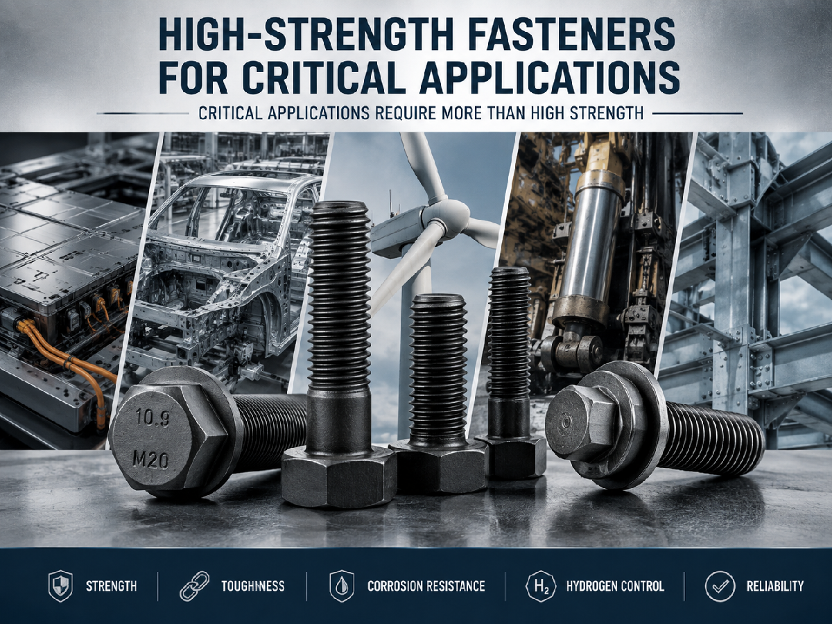
Stripped Screw Threads
The external screw threads or mating internal threads have been damaged.
Symptoms may include:
The screw rotates without loosening or tightening normally
The connection cannot develop the required preload
Threads pull out of the mating material
The screw becomes difficult to remove because of thread deformation
Seized Screw
A seized screw may have an intact drive but resist removal because of:
Corrosion
Galling
Thread deformation
Contamination
Excessive installation preload
Chemical or thermal exposure
Broken Screw
A broken screw has fractured, potentially leaving part of the threaded shank inside the mating component.
These conditions require different removal approaches.
Important Engineering Principle
Before attempting extraction, identify whether the problem involves the drive, the threads, seizure or fracture.
Using the wrong removal method can increase damage and repair costs.
Why Do Screw Heads Become Stripped?
Incorrect Driver-Bit Selection
Using the wrong driver size or drive type is one of the most common causes of screw head damage.
Examples include:
Incorrect Phillips driver size
Using an incompatible cross-recess driver
Undersized internal hexagon bits
Worn driver tips
Poorly fitted external sockets
Drive geometries that appear similar may have different engagement requirements.
For example, different cross-recess systems should not be assumed interchangeable.
Excessive Installation Torque
When the applied torque exceeds the capacity of the drive engagement, the tool may slip or damage the screw recess.
This is especially important for:
Small machine screws
Low-profile screw heads
Precision equipment screws
Screws with limited drive depth
Assemblies with restricted tool access
The drive capacity must be considered alongside the required joint preload.
Incorrect Tool Alignment
A driver that is not correctly aligned with the screw axis can reduce effective contact.
Potential consequences include:
Cam-out
Rounded drive features
Uneven torque transmission
Tool wear
Surface damage
Inadequate Axial Engagement
Some drive systems require sufficient axial force to maintain proper engagement.
Insufficient engagement can cause repeated slipping.
However, excessive axial force may damage delicate components or circuit boards.
Corrosion and Thread Seizure
Corrosion can increase the torque required for removal.
If the screw is seized, applying greater torque through a small or damaged drive may destroy the head before the threaded connection loosens.
Stainless Steel Galling
Certain stainless steel threaded combinations may experience galling.
Galling involves adhesive wear and material transfer between contacting surfaces.
Risk can be influenced by:
Material combination
Surface condition
Lubrication
Installation speed
Thread fit
Applied load
Stainless steel corrosion resistance does not eliminate galling risk.
Repeated Maintenance
Repeated installation and removal can damage screw drives when unsuitable tools or procedures are used.
This is particularly relevant to equipment requiring frequent servicing.
Stripped Screw Failure Diagnosis
| Observed condition | Possible cause | First recommended action |
|---|---|---|
| Driver slips in recess | Worn or incorrect drive | Verify bit type and engagement |
| Internal hexagon rounded | Excessive torque or poor fit | Assess extraction options |
| Screw does not rotate | Corrosion or seizure | Investigate thread condition |
| Screw rotates but remains in place | Damaged threads or retained load | Inspect mating connection |
| Head breaks away | Fracture or severe damage | Evaluate remaining shank |
| Repeated assembly failures | Tooling or process variation | Review installation controls |
| Stainless threads seize | Possible galling | Review material and assembly process |
How to Remove Stripped Screws: Choose the Least Destructive Method First
The objective is to remove the damaged screw while protecting the surrounding component.
A suitable escalation sequence is:
Inspect and identify the damage.
Attempt controlled removal using the correct tool.
Consider limited friction-assisted engagement for minor damage.
Use a suitable extraction tool if necessary.
Consider creating a new drive feature where safe.
Use controlled drilling or professional machining as a last resort.
The appropriate order may change according to the screw geometry and equipment.
Before beginning, make sure the equipment is safely isolated and secured according to the applicable maintenance procedure.
For electrical equipment, follow the required de-energization and lockout procedures.
For pressurized, rotating, suspended or safety-critical equipment, follow the relevant service instructions.
Method 1: Use the Correct Driver with Controlled Axial Pressure
This method is most suitable when the screw drive is only slightly damaged.
Procedure
Clean the screw recess.
Identify the exact drive type and size.
Select a correctly fitted, undamaged driver.
Align the tool with the screw axis.
Apply controlled axial pressure.
Turn slowly in the correct loosening direction.
Most conventional right-hand threads loosen counterclockwise when viewed from the screw head, but left-hand threads and special mechanisms must be identified before applying torque.
Engineering Cautions
Do not continue if the tool repeatedly slips.
Avoid sudden high torque.
Do not force the driver into an incompatible recess.
Protect adjacent surfaces.
When to Stop
If engagement deteriorates, stop and consider another method before the drive becomes completely rounded.
Method 2: Improve Friction for Minor Drive Damage
For some lightly damaged screw heads, a thin friction-enhancing material between the driver and recess may improve engagement.
Possible materials include:
A thin rubber strip
Suitable friction material
Other thin, non-damaging materials compatible with the assembly
Procedure
Confirm that the screw head is only mildly damaged.
Place a thin friction material between the bit and recess.
Maintain alignment.
Apply controlled pressure.
Attempt slow removal.
Suitable Applications
This approach may be considered for low-torque screws in selected:
Consumer products
Electronic housings
Light equipment assemblies
Limitations
This method is unreliable for heavily seized screws or high-torque connections.
Loose material may also contaminate sensitive equipment.
Do not use improvised friction materials where contamination, electrical safety or component damage is a concern.
Method 3: Use a Dedicated Screw Extractor
A screw extractor may be appropriate when the original drive is too damaged for conventional removal.
Different extractor designs are available.
Some engage the damaged drive recess directly. Others require a drilled pilot hole.
General Procedure
Identify the screw size and accessible geometry.
Select an extractor suitable for the screw material and condition.
Secure the workpiece.
Prepare the damaged head according to the extractor manufacturer's instructions.
Use controlled torque to engage and remove the screw.
Important Precautions
Protect surrounding surfaces.
Avoid off-center drilling.
Use suitable cutting tools.
Control chips and debris.
Avoid excessive extractor torque.
Hardened extractors may fracture if overloaded.
A broken extractor can make subsequent machining considerably more difficult.
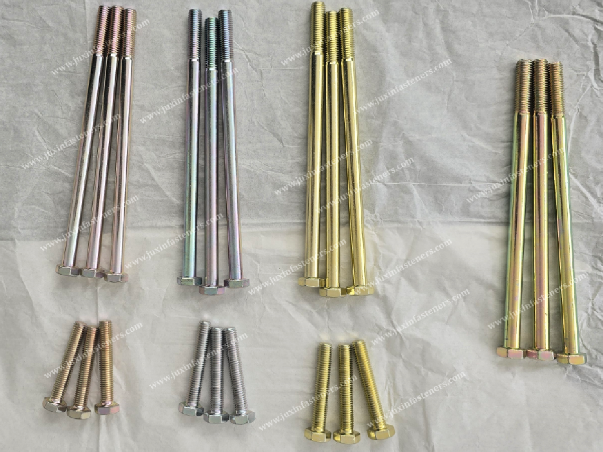
Engineering Recommendation
For expensive equipment or precision threaded components, consider specialist removal before attempting aggressive extraction.
Method 4: Create a New Drive Slot
For certain accessible screw heads, a new slot may be created to permit engagement with a suitable flat-blade driver.
This method may be considered for:
Accessible screw heads
Selected machine components
Noncritical service hardware
General Procedure
Confirm adequate clearance around the screw head.
Protect the surrounding assembly.
Create a suitable slot using controlled equipment.
Engage a correctly sized driver.
Attempt removal using controlled torque.
Important Limitations
This method can create metal debris, sparks or heat depending on the cutting process.
It may be unsuitable near:
Electronic circuits
Batteries
Flammable materials
Sealed components
Precision surfaces
Sensitive coatings
Do not use this method where cutting could compromise the equipment.
Method 5: Controlled Drilling
Drilling may be required when other removal methods are unsuccessful.
Depending on the fastener and joint, the objective may be to remove the head, prepare for extraction or machine out the remaining shank.
Important Considerations
Screw material and hardness
Drill-bit suitability
Hole alignment
Surrounding component thickness
Mating thread condition
Cutting fluid compatibility
Chip control
Risks
Damage to the internal thread
Enlarged mounting hole
Drill breakage
Surface damage
Contamination
Heat generation
For high-value or precision components, controlled machining by qualified maintenance personnel may be preferable.
Method 6: Professional Extraction for Seized or Broken Screws
When a screw is severely seized or fractured below the surface, professional extraction may be required.
Potential techniques depend on the equipment and may include:
Specialized extraction tools
Precision drilling
Controlled machining
Other approved industrial removal processes
The selected method must be compatible with the component material, geometry and service requirements.
Important Safety Note
Heating, welding or aggressive cutting should not be attempted on assembled electrical, pressurized,
flammable or safety-critical equipment without an approved procedure and appropriate qualified personnel.
Which Stripped Screw Removal Method Should You Choose?
| Screw condition | Potential method | Main limitation |
|---|---|---|
| Slightly damaged drive | Correct driver and controlled pressure | Requires remaining engagement |
| Minor recess wear | Friction-assisted engagement | Low-torque applications only |
| Severely damaged recess | Dedicated extractor | Tool compatibility and breakage |
| Accessible damaged head | New drive slot | Cutting access and debris |
| Head cannot be engaged | Controlled drilling | Risk to mating threads |
| Broken or heavily seized shank | Professional extraction | Equipment-specific procedure |
How to Prevent Stripped Screws in OEM Manufacturing
Repair methods are useful, but recurring screw damage should be treated as a manufacturing or design issue.
Prevention begins with selecting a compatible drive system and establishing a controlled installation process.
1. Match the Driver to the Screw
Confirm:
Drive geometry
Bit size
Engagement depth
Bit wear
Tool alignment
A driver that fits loosely can cause damage even when the screw material is acceptable.
2. Specify Suitable Tightening Requirements
Tightening requirements should be based on:
Fastener dimensions
Material and mechanical properties
Joint geometry
Mating material
Friction conditions
Required preload
Assembly process
A generic torque value should not be applied to every screw of the same nominal diameter.
3. Evaluate Drive Capacity
A screw head must provide sufficient drive capacity for the required installation torque.
For example, a shallow internal drive may be unsuitable where the joint requires relatively high tightening torque.
The screw's strength and the drive's torque-transmission capacity are different design considerations.
4. Control Tool Alignment
Manufacturing equipment should maintain appropriate alignment during installation.
For automated screwdriving, review:
Driver positioning
Screw presentation
Bit engagement
Tool calibration
Tightening sequence
Process monitoring
5. Prevent Cross-Threading
Cross-threading can increase installation resistance and lead to drive damage.
Potential causes include:
Misaligned components
Incorrect thread systems
Damaged lead threads
Poor screw feeding
Excessive initial driving speed
6. Consider Corrosion and Galling
Select suitable materials, coatings and assembly conditions.
For stainless steel connections, evaluate the risk of galling rather than assuming that corrosion-resistant materials will always assemble without difficulty.
7. Plan for Maintenance
For equipment requiring repeated access, consider:
Suitable head geometry
Accessible drive location
Appropriate corrosion protection
Replaceable screws
Captive fastening arrangements
Tool-free adjustment where suitable
Production Failure Prevention Matrix
| Production issue | Potential cause | Corrective direction |
|---|---|---|
| Frequent cam-out | Wrong bit or insufficient engagement | Verify drive system |
| Rounded socket heads | Excessive torque or poor tool fit | Review torque and tooling |
| High screw scrap rate | Tool wear or feeding variation | Establish process checks |
| Cross-threading | Misalignment | Improve positioning and starting |
| Stainless thread seizure | Galling or unsuitable assembly conditions | Review material and friction |
| Inconsistent tightening | Friction or tool variation | Validate tightening process |
| Maintenance damage | Poor accessibility | Review head and access design |
Selecting Industrial Screws to Reduce Assembly and Maintenance Problems
A suitable screw should satisfy the mechanical joint requirements while allowing reliable installation and service.
JUXIN FASTENERS supplies relevant categories of industrial screws and fastening components for OEM applications.
Stainless Steel Flange Screws
Stainless steel flange screws may be considered where corrosion resistance and an integrated bearing surface are required.
Potential applications include:
Equipment housings
Outdoor industrial assemblies
HVAC equipment
Selected machinery components
Engineering Considerations
Stainless steel grade
Mechanical property requirements
Flange geometry
Bearing surface
Tool access
Corrosion exposure
Thread galling
Important Distinction
A stainless steel flange screw should not automatically be described as a high-strength replacement for a hardened alloy steel bolt.
Mechanical performance depends on the exact material and property specification.
Stainless Steel Material Selection
Common austenitic stainless steel options include grades associated with 304 and 316.
Other stainless steel families, including certain precipitation-hardening grades, have different properties and heat-treatment requirements.
A designation such as 450 stainless steel must not be used as a blanket substitute for 304 or 316.
Material selection requires the exact grade specification and application conditions.
High-Strength Hex Head Screws
High-strength carbon or alloy steel hex head screws may be suitable for demanding mechanical assemblies.
For specified inch-series products, relevant requirements may include:
SAE J429 mechanical properties
ASME B18.2.1 dimensions
ASME B1.1 thread specifications
SAE Grade 8 is an inch-series mechanical grade and must not be confused with metric property class 8.8.
Engineering Considerations
Mechanical grade
Thread system
Tightening requirements
Head geometry
Corrosion protection
Joint fatigue
Installation tool compatibility
A stronger screw does not automatically prevent drive damage.
Thread-Locking Screws
Some screws use a pre-applied locking feature or coating to provide specified prevailing-torque or retention characteristics.
Potential applications include:
Industrial machinery
Equipment housings
Selected automotive assemblies
Vibration-sensitive equipment
Important Distinction
Thread-locking features address joint retention.
They do not repair a damaged drive recess or compensate for incorrect installation tooling.
Nylon-Patch Screws
A suitable polymer patch may provide prevailing torque in a specified mating thread.
Selection should consider:
Temperature
Chemical exposure
Mating thread
Installation torque
Reuse requirements
Approved performance criteria
Socket Head Cap Screws
Socket head cap screws may be selected where cylindrical head geometry and internal hexagon drive engagement suit the equipment.
For applicable metric products, ISO 4762 defines relevant dimensional requirements.
Engineering Considerations
Internal drive size
Bit engagement
Head clearance
Material strength
Tightening requirements
Maintenance access
A worn or undersized hex bit can damage the socket even when the screw itself meets its specification.
Stainless Steel Thumb Screws
Thumb screws provide manual adjustment or fastening in applications where high tightening torque is not required.
Potential applications include:
Instrument panels
Electronic housings
Equipment covers
Laboratory equipment
Adjustable fixtures
Low-Profile Knurled Head Thumb Screws
These may provide compact manual engagement where suitable clearance is available.
Flared-Collar Knurled Head Thumb Screws
A flared collar may provide a different grip and bearing geometry.
Engineering Considerations
Required manual tightening force
Head diameter
Grip geometry
Thread size
Available clearance
Frequency of adjustment
Thumb screws should not be used as substitutes for high-preload structural bolts without engineering justification.
Industrial Screw Selection Comparison
| Screw category | Primary advantage | Important limitation |
|---|---|---|
| Stainless steel flange screw | Corrosion resistance and integrated bearing geometry | Grade and joint requirements |
| High-strength hex head screw | Specified mechanical strength | Does not prevent drive damage |
| Thread-locking screw | Defined resistance to loosening | Not a substitute for correct preload |
| Socket head cap screw | Compact internal-drive arrangement | Bit engagement and access |
| Thumb screw | Manual operation | Limited tightening capability |
| Custom OEM screw | Application-specific geometry | Drawing and manufacturing review |
Industrial Applications and Screw Failure Prevention
Automotive and EV Manufacturing
Screws may be used in:
Electronic control modules
Equipment brackets
Interior assemblies
Mechanical housings
Production fixtures
Engineering Priorities
Vibration
Fatigue
Corrosion
Tightening consistency
Tool access
Assembly traceability where specified
For safety-critical automotive applications, the complete joint and manufacturing process must be qualified.
Heavy Machinery and Construction Equipment
Potential applications include:
Machinery covers
Structural brackets
Equipment housings
Service panels
Auxiliary assemblies
Engineering Priorities
Mechanical loading
Corrosion
Contamination
Service access
Repeated maintenance
High-strength fasteners should be selected according to the joint design rather than assumed suitable for every heavy-equipment application.
Electronics and Electrical Equipment
Potential applications include:
Electronic housings
Control cabinets
Communication equipment
Server chassis
Instrument panels
Engineering Priorities
Small drive geometry
Controlled tightening
Thread engagement
Tool access
Surface protection
Contamination control
For delicate electronics, removal methods involving drilling, cutting or loose debris require particular caution.
Industrial Automation Equipment
Potential applications include:
Machine frames
Control housings
Equipment covers
Sensor brackets
Maintenance panels
Engineering Priorities
Assembly repeatability
Installation torque
Tool calibration
Vibration
Serviceability
Rework reduction
Medical and Laboratory Equipment
Potential applications include approved equipment housings, instrument panels and laboratory machinery.
Engineering Priorities
Material compatibility
Surface cleanliness
Corrosion resistance
Maintenance access
Applicable equipment requirements
General industrial screws are not automatically qualified for regulated medical or implantable applications.
OEM Custom Screw Design: Preventing Recurring Drive Failures
When an OEM production line repeatedly experiences stripped screw heads, changing the screw material alone may not solve the problem.
A drawing-based review should consider:
Screw head geometry
Drive type
Drive depth
Thread dimensions
Mechanical property class
Material
Surface finish
Mating component
Tool access
Installation torque
Production equipment
Example Engineering Decision
If an assembly repeatedly damages a shallow internal drive, possible corrective directions may include:
Improving bit engagement
Changing the head geometry
Increasing tool clearance
Selecting a suitable alternative drive
Reviewing tightening requirements
Modifying the assembly process
Any design change must be validated against the approved joint requirements.
OEM Supplier Qualification and Production Quality Control
Procurement and supplier development teams should evaluate industrial screws using the complete engineering specification.
Recommended Quality Requirements
Product drawing
Dimensional tolerances
Thread specification
Material grade
Mechanical property requirements
Surface treatment
Drive geometry
Inspection criteria
Packaging
Sample approval
For automated assembly, the supplier and OEM may also need to review dimensional consistency affecting feeding and drive engagement.
Commercial Evaluation
MOQ, tooling requirements, sample arrangements and lead times depend on the actual product specification and quantity.
For custom screws, the feasibility of the selected head and drive geometry should be reviewed before confirming commercial terms.
Total Cost of Screw Drive Failure
The purchase price of a screw is only one part of the manufacturing cost.
Recurring stripped screws may create additional costs through:
Assembly interruptions
Damaged components
Rework labor
Replacement fasteners
Tool wear
Inspection
Scrap
Maintenance downtime
For high-volume manufacturing, reducing recurring screw damage can be more valuable than a small reduction in fastener unit price.
Frequently Asked Questions
What is the easiest way to remove a stripped screw?
For a lightly damaged screw, start with the correct driver size, proper alignment and controlled pressure.
If engagement is insufficient, select a suitable extraction method.
Can a rubber band help remove a stripped screw?
It may help in some minor, low-torque cases, but it is not reliable for severely damaged or seized fasteners.
How do I remove a stripped Allen screw?
First verify the correct internal hexagon bit and inspect the socket.
If it is rounded, a suitable extractor or other controlled removal method may be required.
Can I drill out a stripped screw?
Controlled drilling may be appropriate, but it can damage the mating threads or surrounding component.
Precision equipment may require professional extraction.
Why do screw heads strip during installation?
Common causes include incorrect driver size, tool wear, misalignment, excessive torque and inadequate engagement.
Does stainless steel prevent stripped screw heads?
No. Drive damage depends on the drive geometry, material properties, tooling and installation conditions.
Stainless steel is not automatically more resistant to drive stripping.
Can thread-locking screws prevent stripped screw heads?
No. Thread-locking features are intended to influence joint retention, not prevent damage from incorrect tool engagement.
What is the difference between a stripped screw head and stripped threads?
A stripped head has a damaged drive feature. Stripped threads involve damage to the external or mating internal threads.
Are SAE Grade 8 screws the same as metric class 8.8 screws?
No. They belong to different specification systems and have different mechanical requirements.
Can JUXIN FASTENERS review custom screw drawings?
Yes. JUXIN FASTENERS supports drawing-based OEM inquiries for industrial screws and fastening components.
JUXIN FASTENERS: Industrial Screw and OEM Fastening Solutions
JUXIN FASTENERS supplies standard and drawing-based industrial fastening components for international OEM manufacturers.
Relevant product categories include:
Stainless steel screws
High-strength hex head screws
Flange screws and bolts
Socket head cap screws
Nylon insert lock nuts
All-metal locking fasteners
Self-clinching fasteners
Weld fasteners
Blind rivet nuts
Threaded inserts
Custom CNC-machined fastening components
Specific material, geometry, surface treatment, inspection, MOQ and delivery requirements are reviewed according to the project.
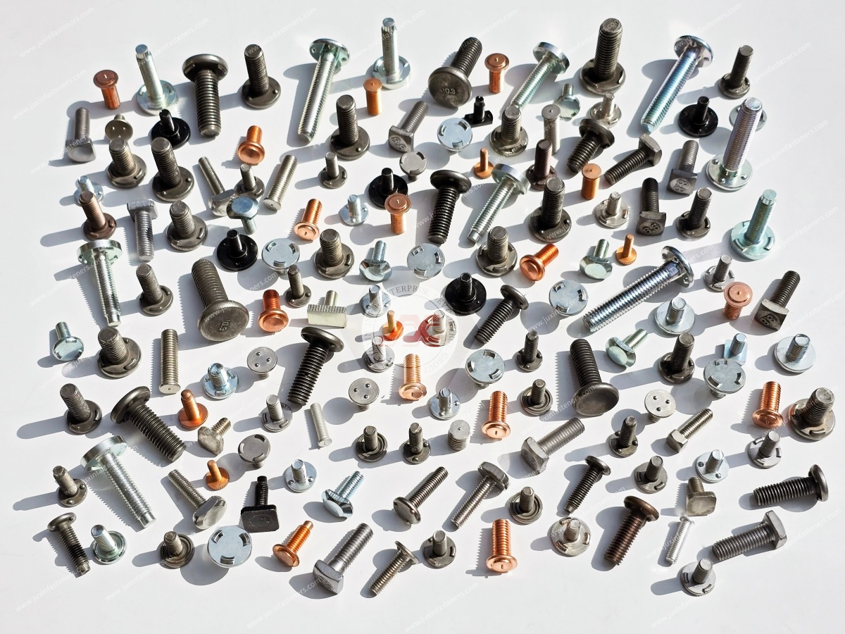
Request an Industrial Screw Engineering Review and OEM RFQ
Are you experiencing repeated screw head damage, assembly difficulties, corrosion-related seizure or excessive maintenance rework?
Or are you sourcing stainless steel screws, high-strength hex head screws, flange screws, locking fasteners or custom OEM fastening components?
JUXIN FASTENERS welcomes technical and purchasing inquiries from mechanical engineers, design engineers, manufacturing engineers,
production managers, procurement specialists, supplier development teams and supply chain managers.
For an efficient review, please provide:
2D drawing or product specification + thread designation + screw dimensions + head and drive geometry + material + mechanical requirements
+ surface finish + mating component material + installation method + tightening requirements + operating environment + sample quantity + order volume + target delivery schedule.
For recurring assembly failures, include photographs of the damaged screw, the mating component and the installation tool where available.
These details help distinguish screw design problems from installation-process problems.
Company: Juxin Fasteners
Website: https://www.juxinfasteners.com/
Email: info@juxinfasteners.com
Send your industrial screw drawings, assembly requirements and RFQ to JUXIN FASTENERS for technical review and quotation.
Contact Us
Tel.:
+86 020 8621 0320
+86 020 3121 6067
E-mail:
Technical Support:
Navigation
SEND INQUIREY



