
Call Us
+86 136 6007 9809
Call Us
+86 136 6007 9809

Aug. 26, 2023
In marine equipment, commercial vehicle bodies, recreational equipment, HVAC systems, electrical enclosures, industrial equipment and composite structures,
engineers often need to create a reliable threaded mounting point in materials that do not behave like conventional structural sheet steel.
Examples include:
Fiberglass-reinforced plastic
Plastic panels
Composite laminates
Plywood
Thin boards
Sandwich panels
Selected low-density substrates
Other materials where a conventional rigid insert may create excessive local stress
Traditional sheet-metal fastening methods can be unsuitable when the parent material is soft, brittle, thin or prone to localized cracking.
A conventional screw may strip the substrate.
A rigid insert may concentrate load around a relatively small bearing area.
A standard blind rivet nut may not provide the deformation pattern required by the application.
Jack blind rivet nuts, commonly called jack nuts, use an expandable body that forms multiple legs or “petals” behind the parent material during installation.
The resulting geometry can create a larger backside bearing area than a simple cylindrical interface.
This makes jack nuts a specialized fastening option for selected soft-material and thin-panel applications.
However, the engineering objective is not simply to obtain the largest possible expansion.
The complete joint must be evaluated through:
Parent material
Panel construction
Panel thickness
Hole diameter
Hole quality
Grip condition
Jack nut geometry
Petal formation
Thread size
Installation method
Mating screw
Applied load
Environmental exposure
Service requirements
For OEM procurement, these characteristics should be controlled through an approved drawing and application-specific specification.
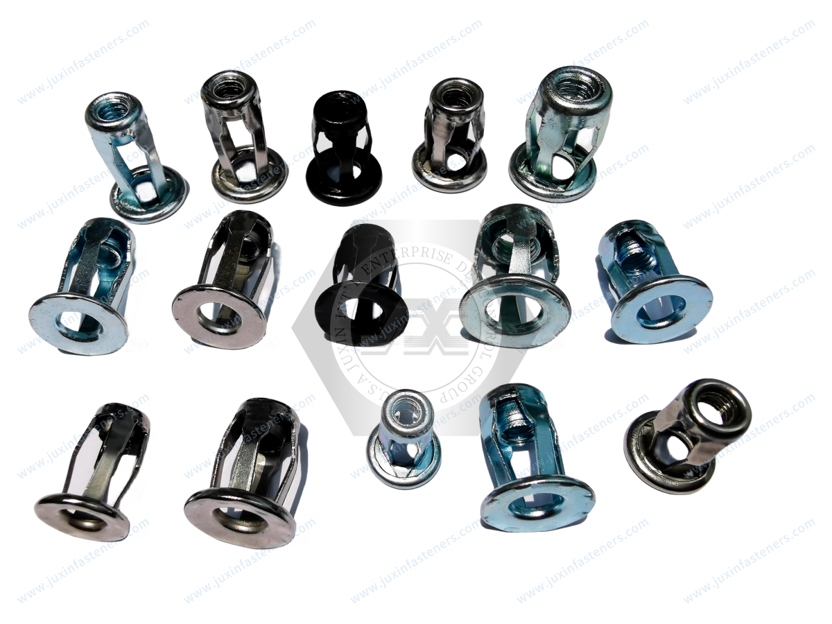
A jack blind rivet nut is a specialized blind threaded insert that creates an internal thread through single-sided installation.
It is commonly known as a:
Jack nut
Jack blind nut
Expandable blind nut
Petal expansion nut
Multi-leg blind threaded insert
The product is inserted into a prepared hole from the accessible side.
During installation, the body deforms behind the panel and forms multiple bearing legs.
The front flange remains on the accessible side while the expanded portion engages the rear side of the substrate.
The resulting assembly provides an internal thread for a mating screw.
Although jack nuts belong to the broader family of blind threaded inserts, their deformation mechanism is different from many conventional blind rivet nut designs.
A typical blind rivet nut forms a controlled collapsed section behind the panel.
A jack nut forms multiple outward-folding legs or petals.
This difference is important when the parent material is:
Soft
Brittle
Thin
Flexible
Composite
Laminated
Low density
The correct product therefore depends on the substrate and loading condition.
For the broader blind rivet nut engineering principles, see Blind Rivet Nuts: Engineering Principles, Installation Mechanics & Industrial Solutions.
The defining feature of many jack nut designs is the formation of multiple legs behind the parent panel.
During installation:
The jack nut is inserted into the prepared hole.
The installation mechanism engages the threaded component.
The internal assembly moves relative to the body.
The deformable section begins to collapse.
Multiple legs fold outward behind the panel.
The legs create a backside bearing interface.
The front flange remains against the accessible surface.
The internal thread remains available for the mating screw.
The exact deformation sequence depends on the product geometry and installation method.
The key engineering value of petal expansion is load distribution.
Instead of relying only on a small localized area around the hole, the expanded legs can create multiple contact areas behind the panel.
This may reduce local stress concentration in suitable soft or brittle substrates.
However, the larger bearing geometry does not automatically guarantee a higher pull-out capacity.
The actual joint depends on the substrate, geometry and installation condition.
Soft materials can fail differently from steel sheet.
Potential failure mechanisms include:
Local crushing
Cracking
Delamination
Pull-through
Hole enlargement
Material tearing
Thread stripping
The metal jack nut may remain intact while the parent material fails first.
This is why the substrate should always be treated as part of the fastening system.
Plastic panels are one potential application area for jack nuts.
Depending on the plastic formulation and panel design, the substrate may have different:
Strength
Stiffness
Ductility
Creep behavior
Stress-relaxation behavior
Chemical resistance
Temperature response
Therefore, “plastic” is not a complete material specification.
The exact polymer and panel construction should be identified when joint performance is important.
Fiberglass-reinforced plastic and other FRP structures can behave differently from homogeneous plastics.
Potential characteristics include:
Fiber orientation
Resin system
Laminate construction
Thickness
Local stiffness
Delamination sensitivity
A jack nut may be considered where the expansion geometry is compatible with the panel.
Prototype validation should use the actual laminate construction.
Composite panels can contain several layers with different mechanical properties.
For example:
Outer skin
Core
Inner skin
The fastening requirement must therefore consider the complete panel architecture.
A jack nut designed for a single solid sheet should not automatically be assumed suitable for a sandwich construction.
Certain equipment and vehicle structures may use plywood or laminated board.
Jack nuts can provide a threaded fastening point where the backside is inaccessible.
The engineer should consider:
Wood species or board construction
Moisture exposure
Panel thickness
Local crushing
Edge distance
Hole quality
Expected service load
The correct configuration must be validated in the actual board material.
Sandwich panels require special attention because the core may not provide the same bearing behavior as the outer skins.
Potential panel constructions include:
Foam core
Honeycomb core
Composite skins
Laminated skins
The jack nut's expansion must interact with an appropriate structural layer.
A fastener should not be installed into a weak core simply because the overall panel appears thick.
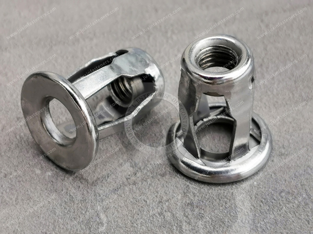
Thin panels can benefit from a fastening design that creates a broader backside bearing interface.
However, thinness alone does not determine suitability.
The engineer should consider:
Panel material
Local stiffness
Hole size
Edge distance
Load direction
Installation condition
A very thin but stiff composite can behave differently from a thicker flexible plastic panel.
Jack nuts are installed from one accessible side.
This is useful where the rear surface is:
Enclosed
Hidden
Difficult to reach
Inside a hollow structure
Blocked by another component
Single-sided installation can simplify assembly planning.
The rear-side expansion occurs automatically during installation rather than requiring an operator to hold a separate nut behind the panel.
Potential applications include:
Hollow equipment housings
Vehicle body sections
Composite enclosures
Tubular structures
HVAC assemblies
Equipment panels
Before selecting a jack nut, the engineer should verify that the internal cavity provides enough space for the expanding legs.
The internal geometry is therefore part of the installation specification.
The expanded legs create multiple bearing interfaces behind the panel.
The effective bearing area depends on the actual deformation geometry.
It is influenced by:
Jack nut design
Panel thickness
Hole diameter
Installation process
Substrate stiffness
Available rear-side space
The nominal number of legs should therefore not be treated as a complete measure of joint performance.
One reason jack nuts are considered for soft materials is that the expanded petals can distribute load across a broader area.
This may reduce localized stress compared with a smaller concentrated contact area.
However, stress distribution depends on the actual geometry.
A poorly matched fastener can still create excessive local loading.
This is why application testing remains important.
Brittle materials can be sensitive to concentrated loading.
Examples may include:
Certain fiberglass laminates
Rigid plastics
Composite skins
Laminated boards
Potential failure can begin around the hole or beneath the expanded legs.
The fastening design should therefore consider:
Bearing area
Edge distance
Hole quality
Installation deformation
Applied load
Panel construction
The mounting hole is a critical part of the jack nut system.
The hole must be large enough to accept the body while remaining compatible with the intended installation behavior.
An oversized hole may reduce effective engagement.
An undersized hole may prevent correct insertion or cause damage.
The required hole diameter should therefore come from the selected product drawing.
Jack nuts can be useful in applications where the parent material has some manufacturing variation.
However, this does not mean that hole tolerance is irrelevant.
Hole diameter, roundness and edge condition can still affect:
Insertion
Flange seating
Petal formation
Final retention
The correct tolerance should be established from the specific product and application.
Burrs may be generated through:
Drilling
Punching
Routing
Cutting
Other fabrication processes
A large burr can change the effective hole geometry.
For production applications, the hole-making process should be controlled according to the assembly requirement.
Grip range is the range of parent-material conditions for which the jack nut is designed to form the intended installation geometry.
The correct grip should consider:
Minimum panel thickness
Maximum panel thickness
Stack-up
Laminate thickness
Coating
Local reinforcement
Grip range should not be selected by panel thickness alone when multiple layers are involved.
Some composite applications contain multiple layers.
For example:
Outer skin + core + inner structural layer
The jack nut may need to engage a specific layer rather than simply the total panel thickness.
The engineer should identify where the expanding legs are intended to bear.
This is a particularly important consideration for sandwich structures.
Installation force depends on:
Jack nut geometry
Material
Grip
Parent substrate
Installation tool
It should be established through the product-specific installation process.
A generic installation-force value should not be applied across different jack nut designs.
Installation stroke is the amount of movement used to create the required petal deformation.
It is different from installation force.
The correct stroke depends on the fastener design and installation method.
Over-forming or under-forming can change the final joint geometry.
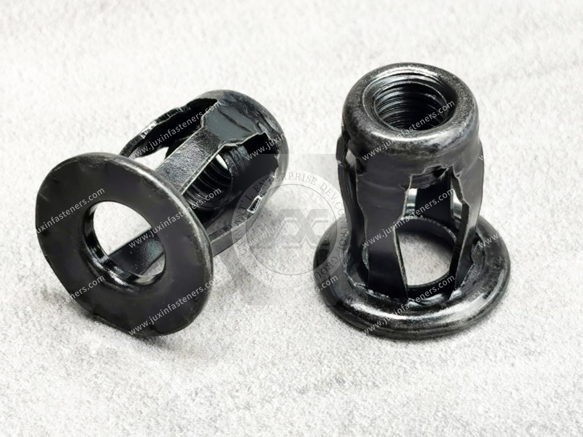
The tool must be compatible with the jack nut configuration.
Consider:
Thread size
Installation mechanism
Tool interface
Required force
Required stroke
Operator access
Production volume
For high-volume production, the installation process should be standardized and validated.
Jack nuts can be designed for metric or inch-series applications depending on the product configuration.
Possible applications may use:
M4
M5
M6
M8
M10
UNC
UNF
These examples should not be interpreted as a universal stocked range.
The actual available configuration should be confirmed against the JUXIN FASTENERS product specification.
The jack nut creates an internal thread for a mating screw.
The engineer should specify:
Nominal diameter
Thread pitch
Thread system
Thread tolerance where applicable
Thread engagement
Screw material
Screw finish
The mating screw is part of the complete joint.
Thread engagement must be adequate for the intended assembly.
The appropriate engagement depends on:
Thread size
Nut material
Screw material
Applied load
Assembly torque
Service conditions
A larger screw does not automatically make a soft-material joint stronger.
The substrate may remain the limiting component.
Pull-out occurs when the installed jack nut is pulled away from the panel.
In soft materials, the substrate may fail before the metal component.
Potential failure modes include:
Petal deformation
Panel pull-through
Hole enlargement
Local crushing
Material tearing
Therefore, pull-out validation should use the actual panel.

Pull-through occurs when the fastening assembly is drawn through the parent material.
This is particularly important for:
Thin panels
Soft plastics
Composite skins
Laminated structures
A wide expansion geometry may help distribute load, but the actual result depends on the substrate.
The mating screw can apply rotational torque to the jack nut.
Potential failure can involve:
Jack nut rotation
Hole enlargement
Petal movement
Substrate deformation
This should be distinguished from axial pull-out.
A jack nut that performs well in axial loading may still require separate evaluation for rotational loading.
Brittle materials may crack around the installation hole if local stress is excessive.
Potential contributing factors include:
Hole geometry
Edge distance
Installation deformation
Substrate brittleness
Fastener geometry
Assembly loading
The installation process should therefore be validated in the actual substrate.
The distance from the hole to the panel edge can influence joint behavior.
If the hole is too close to an edge, the expanded legs may interact with a smaller amount of surrounding material.
Potential consequences include:
Edge cracking
Pull-through
Local deformation
Reduced bearing support
The appropriate edge distance should be established from the actual application.
The engineer should also consider nearby:
Bends
Cutouts
Reinforcements
Other holes
Panel edges
Mounting features
These can change local stiffness and available bearing area.
Some polymers can exhibit creep under sustained load.
This means that a joint that is initially stable may behave differently after prolonged exposure to load and temperature.
For plastic applications, engineers should consider:
Polymer type
Temperature
Sustained load
Load duration
Panel thickness
Fastener geometry
Long-term behavior should be validated for critical applications.
Some polymer materials may also experience stress relaxation.
This is particularly relevant where the fastening system maintains a sustained clamping condition.
The design should therefore consider the long-term behavior of the substrate rather than only initial installation performance.
Plastic and composite materials can change mechanical behavior with temperature.
Potential effects include:
Reduced stiffness
Increased deformation
Dimensional change
Creep
Stress relaxation
For applications exposed to significant temperature variation, validation should use the actual material and environmental conditions.
Marine, HVAC and outdoor equipment may experience:
Humidity
Condensation
Water exposure
Salt-containing environments
The jack nut material and finish should be selected accordingly.
However, a jack nut should not automatically be described as waterproof or sealed simply because it expands behind the panel.
If the assembly requires environmental sealing, the sealing architecture must be engineered separately.
Marine equipment can combine:
Fiberglass
Composite structures
Stainless steel
Aluminum
Moisture
Salt exposure
Jack nuts may be considered for selected interior and equipment mounting applications.
Material compatibility and corrosion behavior should be evaluated as part of the complete assembly.
Commercial vehicle equipment may contain:
Composite body panels
Utility compartments
Interior panels
Equipment housings
Service-access components
A jack nut can provide a threaded mounting point where rear access is limited.
The actual application should be validated against vibration, temperature and substrate behavior.
HVAC equipment may use thin panels and formed housings where access to the rear side is restricted.
Jack nuts may be considered for:
Brackets
Covers
Service panels
Equipment accessories
The substrate and environmental conditions should determine the material and configuration.
Electrical enclosures may use plastic, composite or thin sheet-metal panels.
Jack nuts can create internal threaded mounting points for:
Brackets
Covers
Cable-management components
Internal equipment
Accessories
Where electrical grounding or EMC requirements exist, the fastening system should be separately engineered and validated.
A jack nut should not automatically be considered an EMI/RFI grounding component.
Industrial equipment can combine different substrate materials.
Potential applications include:
Machine covers
Guarding
Equipment panels
Instrument housings
Lightweight structures
The jack nut selection should be based on the actual parent material and loading.
One advantage of using a specialized expandable insert is that the thread is created by a metal component rather than relying directly on a molded or cut plastic thread.
This can simplify component attachment where the panel needs a reusable threaded mounting point.
However, the long-term performance remains dependent on the plastic substrate.
The metal thread does not eliminate plastic creep or substrate deformation.
Fiberglass panels may require careful load distribution because the laminate can have directional and layered mechanical behavior.
The engineer should consider:
Fiber orientation
Laminate thickness
Resin system
Hole quality
Edge distance
Load direction
The actual laminate should be used for prototype validation.
A sandwich panel should be treated as a layered structure rather than a single material thickness.
The engineer should identify:
Skin thickness
Core material
Core thickness
Structural backing
Fastener bearing layer
The jack nut must be positioned so that its expansion interacts with a suitable structural layer.
Potential jack nut material categories may include:
Carbon steel
Stainless steel
Other application-specific materials where available
Selection should consider:
Parent material
Corrosion environment
Joint loading
Weight
Temperature
Surface treatment
The exact material availability should be confirmed for the selected JUXIN FASTENERS configuration.
Carbon steel can provide a practical solution for many general industrial applications.
Possible applications include:
Equipment housings
Commercial vehicle components
HVAC assemblies
General machinery
The appropriate surface treatment should be selected according to the service environment.
Stainless steel may be considered for applications requiring increased corrosion resistance.
Potential applications include:
Marine equipment
Outdoor enclosures
Corrosion-exposed equipment
Industrial environments
A2/A4 terminology may be relevant to certain stainless fastener specifications, but the exact material grade and applicable standard should be confirmed for the specific jack nut product.
For carbon steel jack nuts, potential finishes may include zinc-based coatings or other application-specific treatments.
For stainless steel components, passivation may be considered where applicable.
The finish should be specified based on:
Environment
Parent material
Appearance
Corrosion requirements
Customer specification
A coating designation should not be treated as a universal service-life guarantee.
Dissimilar metal combinations can require corrosion evaluation.
Potential combinations include:
Steel jack nut + aluminum panel
Stainless steel jack nut + aluminum panel
Steel jack nut + composite structure containing conductive components
The engineer should consider:
Moisture
Electrical contact
Surface treatment
Material pairing
Service environment
Jack nuts should not be assigned unrelated fastener standards simply because a standard appears in a general fastener catalog.
The product geometry, material and intended application should determine which standards are applicable.
For stainless steel components, relevant international standards may apply where their scope covers the specific fastener and material requirement.
For dimensions and thread requirements, the customer's drawing should control the final specification.
This approach avoids incorrect references such as treating generic blind rivet or wire-material standards as universal jack-nut product standards.
A supplier should not automatically describe jack nuts as “ISO 8848 / ISO 8849 compliant” without confirming the actual scope and product applicability of those standards.
A correct OEM specification should instead identify the exact:
Product drawing
Dimensions
Thread
Material
Finish
Installation requirement
Functional requirement
This provides procurement teams with a more useful and auditable product definition.
Validation should use the actual:
Jack nut
Parent material
Panel thickness
Hole
Installation process
Mating screw
Load condition
This is particularly important for soft materials.
A test performed in steel sheet cannot automatically predict behavior in fiberglass or plastic.
Where axial retention is important, testing should reproduce the actual substrate.
Important variables include:
Panel thickness
Material
Hole diameter
Edge distance
Jack nut configuration
Installation process
Loading direction
The acceptance criterion should come from the customer engineering specification.
Where the mating screw applies significant torque, rotational resistance should be evaluated separately.
Potential measurements may focus on:
Nut rotation
Hole deformation
Petal movement
Substrate failure
The test configuration should reflect the actual assembly.
For soft-material applications, the question is not simply:
“How strong is the jack nut?”
The more useful question is:
“Which component of the complete joint fails first?”
Potential limiting components include:
Plastic panel
Composite laminate
Hole
Petal interface
Jack nut body
Internal thread
Mating screw
This is a critical engineering distinction when designing lightweight assemblies.
The number of expansion legs should not be converted directly into a strength claim.
Four-leg expansion describes a geometry.
Actual joint capacity depends on:
Petal geometry + bearing area + substrate + hole + installation + load direction
This is why product geometry and application validation must be considered together.
In steel sheet, engineers may focus heavily on fastener strength.
In plastic or composite structures, the substrate can become the limiting component.
The joint may fail through:
Crushing
Cracking
Delamination
Pull-through
Creep
Stress relaxation
This means the correct fastening strategy must be designed around the parent material, not only the metal insert.
A larger backside bearing area can reduce local pressure.
However, a larger expansion geometry may also require:
More internal space
Adequate panel clearance
Suitable substrate thickness
Correct installation deformation
The optimal geometry is therefore application-dependent.
Jack nuts may be suitable for applications where the substrate has some dimensional variation.
But this does not mean that any hole size will work.
The hole still controls:
Initial fit
Flange seating
Body positioning
Petal formation
Final retention
The correct hole should therefore remain a controlled drawing parameter.
A composite panel may have several layers.
Therefore, “panel thickness” can be misleading if the expansion legs must bear against a particular structural layer.
The supplier should understand:
Where is the fastener installed, and what material is actually behind the expansion zone?
This question can be more important than total panel thickness.
PA, PC, POM, PP, PVC and other polymers have different mechanical and environmental behavior.
Therefore, an RFQ stating only:
“Plastic panel”
may not provide enough information for engineering selection.
The supplier should receive the actual polymer or customer material specification whenever joint performance is important.
A fiberglass laminate, a solid plastic sheet and a foam-core sandwich panel may have completely different fastening behavior.
The same jack nut should not automatically be approved across all three structures.
The joint should be validated in the actual panel construction.
A practical engineering selection sequence is:
1. Identify the substrate
2. Define panel construction
3. Determine thickness
4. Identify minimum and maximum stack-up
5. Define hole diameter
6. Confirm rear-side clearance
7. Select thread size
8. Determine required thread engagement
9. Select jack nut geometry
10. Confirm petal expansion clearance
11. Select material
12. Select surface treatment
13. Define installation method
14. Validate pull-out / pull-through / rotation as required
15. Release the approved drawing
Procurement teams should avoid an RFQ that says only:
“Jack nut, M6.”
A controlled OEM RFQ should define:
Part number
Drawing
Revision
Thread
Material
Finish
Panel material
Panel thickness
Hole diameter
Grip range
Installation method
Functional requirements
Annual volume
Packaging
Documentation
This allows suppliers to quote the actual engineered product rather than a visually similar alternative.
Supplier development teams may evaluate:
Drawing control
Material control
Surface-treatment control
Thread inspection
Dimensional inspection
Production consistency
Lot identification
Change management
Nonconformance control
Packaging
Sample approval
The exact requirements should be aligned with the customer's supplier-quality system.
A jack nut drawing may need to identify:
Thread size
Thread pitch
Thread tolerance
Flange dimensions
Body dimensions
Petal geometry
Overall length
Grip range
Material
Surface treatment
Critical tolerances
Functional requirements
The drawing should distinguish product dimensions from application-level requirements.
Where the installation process is critical, the assembly documentation should also define:
Hole diameter
Hole tolerance
Panel material
Panel thickness
Installation orientation
Tooling
Installation parameters
Visual acceptance criteria
This reduces variation between production operators or production sites.
For commercial vehicle programs, procurement teams may require:
Approved drawing
Prototype samples
Production validation
Material documentation
Surface-treatment requirements
Packaging specifications
Forecast volumes
Change-control requirements
The jack nut should be treated as part of the vehicle component assembly rather than as an isolated commodity item.
Marine and outdoor applications require additional consideration of:
Corrosion
Moisture
Salt exposure
Material compatibility
Composite substrate
Service conditions
Stainless steel may be considered where appropriate, but the exact material and application requirements must be confirmed.
JUXIN FASTENERS supports B2B requirements for blind threaded inserts and application-specific fastening components.
For jack nut projects, the engineering evaluation should consider:
Substrate
Panel construction
Thickness
Hole
Grip
Thread
Petal expansion
Material
Surface treatment
Installation
Loading
Environment
This allows the product selection to be based on the actual assembly rather than a generic catalog description.
Jack nuts are part of the broader blind threaded fastening family.
Depending on the application, other solutions may include:
Standard blind rivet nuts
Closed-end blind rivet nuts
Sealing blind rivet nuts
Large-cap blind rivet nuts
Anti-rotation blind rivet nuts
Aluminum blind rivet nuts
Automotive blind rivet nuts
For EV enclosure applications requiring sealing considerations, see Sealing Blind Rivet Nuts for EV Battery Enclosures.
For lightweight aluminum applications, see Aluminum Closed-End Blind Rivet Nuts.
When the parent structure is plastic or polymer-based, the complete assembly may also require:
Plastic screws
Plastic bolts
Plastic nuts
Plastic washers
Spacers
Clips
Cable clamps
Metal-to-plastic fastening combinations
See Custom Plastic & Nylon Fasteners for Industrial Applications for broader polymer fastening considerations.
For a jack blind rivet nut RFQ, provide:
2D drawing
3D model where available
Part number
Drawing revision
Thread size
Thread pitch
Thread system
Panel material
Polymer grade where applicable
Composite construction where applicable
Panel thickness
Minimum and maximum stack-up
Hole diameter
Hole tolerance
Hole-making process
Edge distance
Rear-side clearance
Required thread engagement
Installation method
Mating screw
Assembly torque
Environmental conditions
Material requirement
Surface finish
Prototype quantity
Annual production volume
Packaging requirements
Inspection requirements
Documentation requirements
A product name does not contain enough information to evaluate a soft-material fastening application.
Compare:
“M6 jack nut”
with:
“M6 internal thread jack nut for a fiberglass laminate, defined panel thickness, specified hole diameter, limited rear-side clearance, required screw engagement and controlled installation process.”
The second description gives the supplier an engineering basis for evaluating the product.
This improves communication between:
Design engineering
Manufacturing engineering
Purchasing
Supplier development
Quality
Supply chain
The prototype should represent the production assembly as closely as possible.
Use:
Actual panel material
Actual panel thickness
Actual hole
Actual jack nut
Actual installation tool
Actual mating screw
This helps identify substrate-specific failure modes before production release.
Once the jack nut has been approved, the production process should maintain control of:
Hole size
Hole condition
Fastener orientation
Installation parameters
Stud or screw compatibility
Visual seating
Finished assembly condition
Where a process characteristic is critical, it should be identified in the customer's control plan or assembly specification.
Jack blind rivet nuts provide a specialized solution for creating internal threaded mounting points in selected soft, brittle, composite and thin-panel applications.
The four-leg petal expansion mechanism can distribute load across multiple backside bearing areas.
The most important principles are:
Jack nuts are a specialized type of blind threaded insert.
They create an internal thread through single-sided installation.
Their defining feature is expandable petal or leg geometry.
Petal expansion can increase backside bearing area.
Larger bearing area does not automatically mean higher joint strength.
Soft and brittle substrates may fail before the metal insert.
Plastic, fiberglass and composite panels have different mechanical behavior.
Hole diameter remains a critical specification.
Grip range must reflect the actual substrate and stack-up.
Rear-side clearance must accommodate the expansion geometry.
Pull-out, pull-through, rotation and cracking are different failure modes.
Installation force and installation stroke are separate process variables.
Material and surface treatment should be selected according to the environment.
A sealing requirement must be engineered separately from petal expansion.
Application-level validation should use the actual substrate and installation process.
OEM procurement should control the product through an approved drawing and complete RFQ.
If your application requires jack blind rivet nuts, jack nuts, petal expansion fasteners or specialized blind threaded inserts for plastic, fiberglass,
composite or thin-panel structures, contact JUXIN FASTENERS with your engineering and procurement requirements.
For technical evaluation, please provide:
2D drawing
3D model where available
Thread specification
Panel material
Panel construction
Panel thickness
Hole diameter
Grip condition
Rear-side clearance
Required load direction
Mating screw
Surface treatment
Environmental conditions
Prototype quantity
Expected production volume
Email: info@juxinfasteners.com
JUXIN FASTENERS can review the application information and determine the product configuration and technical parameters that need to be confirmed for sampling, validation and OEM production sourcing.
For broader blind threaded insert requirements, see Blind Rivet Nuts: Engineering Principles, Installation Mechanics & Industrial Solutions.
 MORE NEWS

Sep. 25, 2026

Sep. 25, 2026

Sep. 25, 2026
Contact Us
Tel.:
+86 020 8621 0320
+86 020 3121 6067
E-mail:
Technical Support:
Navigation
SEND INQUIREY