
Call Us
+86 136 6007 9809
Call Us
+86 136 6007 9809

Aug. 16, 2023
In industrial machinery, automation equipment, assembly fixtures, adjustable workstations and modular tooling, components often need to be positioned quickly, held securely and released without tools.
A conventional bolt or screw can provide a strong fixed connection, but it does not provide the controlled linear movement required for repeated indexing and repositioning.
Knob-grip retractable spring plungers solve this problem by combining a threaded mounting body, spring-loaded plunger pin and manual pull knob into a compact positioning mechanism.
When the knob is pulled, the plunger pin retracts from a locating hole or mating feature. When released, the internal spring returns the pin toward its engaged position.
Depending on the design, a twist-to-lock or rest-position mechanism can hold the plunger in the retracted position during setup or workpiece loading.
These components are commonly considered for:
Machine tooling
Automation fixtures
Workholding systems
Indexing tables
Adjustable machine components
Modular manufacturing cells
Assembly equipment
Packaging machinery
Industrial equipment
Electronics equipment
Medical equipment
Aerospace equipment
Semiconductor manufacturing equipment
Inspection fixtures
The correct spring plunger is not selected only by thread size.
Engineers should also consider:
Spring force
Working stroke
Extended length
Retracted length
Nose geometry
Nose material
Mounting thread
Body material
Side loading
Cycle frequency
Environmental exposure
Locking function
Operator access
JUXIN FASTENERS supplies industrial fastening and positioning components for OEM applications, with more than 20 years of fastener experience.
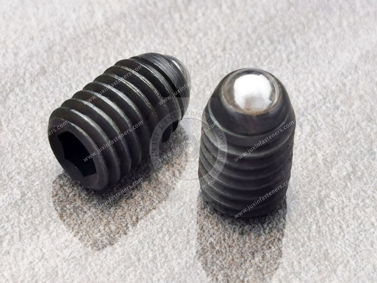
A knob-grip retractable spring plunger is a spring-loaded mechanical positioning device designed to provide controlled linear engagement and manual retraction.
A typical configuration contains:
Threaded body
Compression spring
Plunger pin
Knob or grip
Nose or contact end
The threaded body is installed into a tapped hole in the machine, fixture or structural component.
The internal spring biases the plunger toward the extended position.
The operator can pull the knob to retract the pin.
When the knob is released, the spring returns the pin toward the engaged position.
This makes the component useful for applications where a mechanical element must move repeatedly between an engaged and disengaged position.
The basic operating sequence is straightforward.
The spring pushes the plunger pin toward the mating feature.
The pin may enter:
A drilled hole
Indexing hole
Slot
Groove
Recess
Fixture locating feature
The operator pulls the knob.
The plunger pin moves against the spring force and clears the mating feature.
This allows:
Adjustment
Workpiece loading
Fixture changeover
Component repositioning
Machine setup
When the operator releases the knob, the spring drives the pin toward the extended position.
The actual engagement behavior depends on the geometry of the mating component.
For reliable indexing, the receiving hole or feature should be designed to provide sufficient clearance and engagement without creating unnecessary interference.
Although spring plungers are relatively compact, each component contributes to the operating behavior.
The body provides the mounting interface.
The thread may be selected according to:
Metric specification
Inch specification
Mounting material
Available installation space
Required mechanical retention
The spring provides the return force.
Important parameters include:
Initial force
Working force
Spring rate
Compressed length
Available stroke
The pin engages with the mating feature.
Its geometry can affect:
Engagement
Wear
Contact stress
Alignment tolerance
Release behavior
The knob provides a manual interface for retraction.
Its size and shape can affect:
Operator grip
Accessibility
Required actuation movement
Clearance
One of the most important design distinctions is that spring force is not the same as positioning load.
A spring plunger may have a defined spring force at a particular position, but the actual external load acting on the plunger can depend on:
Equipment movement
Vibration
Gravity
Acceleration
Side load
Contact geometry
Operator force
Workpiece movement
The spring must provide enough force to maintain the intended engagement under the actual application conditions.
However, increasing spring force is not automatically better.
Excessive force can increase:
Operator effort
Contact stress
Wear
Friction
Difficulty during setup
The engineering target is therefore the required operating window rather than the maximum possible spring force.
The internal spring generally has a preload when assembled.
As the plunger moves, spring compression changes and the force changes according to the spring characteristics.
Therefore, the specification should distinguish between:
Initial spring force
Force at a specified stroke
Maximum working force
Spring travel
For an OEM application, the customer drawing may define a force requirement at one or more positions.
This is more useful than simply specifying “heavy spring” or “light spring.”
Threaded spring plungers are commonly installed into a tapped mounting hole.
The installation design should consider:
Thread size
Thread engagement
Body length
Mounting depth
Jam-nut or locking arrangement if required
Available clearance
Plunger travel
The body should be installed sufficiently to achieve secure mounting while preserving the intended operating geometry.
Changing the insertion depth of a threaded plunger can change the installed position of the component relative to the mating feature.
However, insertion depth should not be treated as a universal method of precisely calibrating spring force.
If a specific spring force is critical, the force characteristic should be defined as part of the spring-plunger specification.
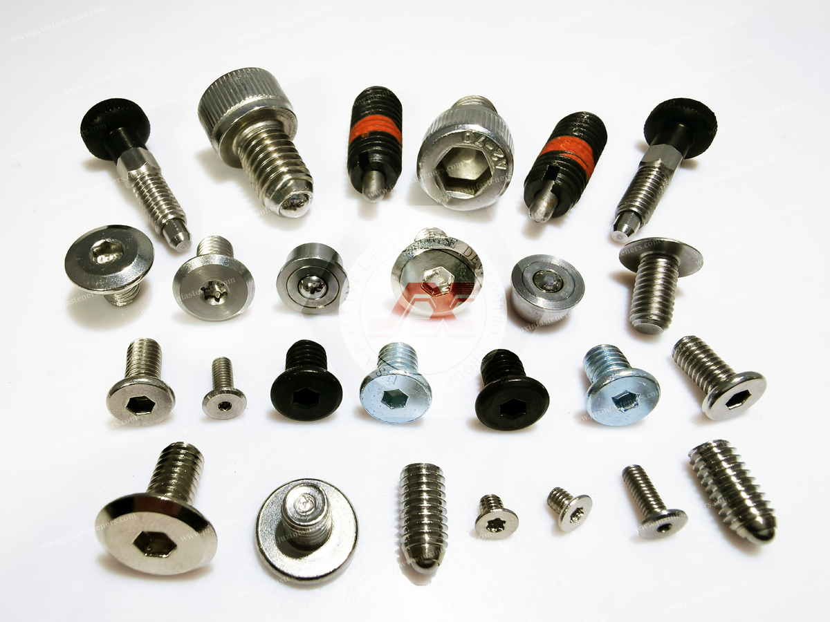
The knob is the human interface of the mechanism.
A practical knob design should consider:
Grip diameter
Pull direction
Available hand clearance
Operating frequency
Glove use
Surrounding equipment
Required retraction distance
In automated equipment, operators may need to release and engage a fixture repeatedly during changeovers.
A properly sized knob can make this operation easier without requiring additional tools.
However, knob size should also remain compatible with the available installation envelope.
Some spring plunger configurations include a rest-position or twist-to-lock function.
The operating principle is generally:
Pull the knob
Retract the plunger
Rotate the knob into the locking position
Hold the plunger in the retracted state
Rotate or release the mechanism to return it to normal operation
This can be useful during:
Fixture setup
Workpiece loading
Machine adjustment
Tool changes
Position changes
Equipment maintenance
The exact locking movement and angle depend on the specific product design.
Therefore, OEM drawings should define the actual mechanism rather than assuming that every retractable spring plunger uses the same locking geometry.
Twist-to-lock functionality should not be evaluated only as a mechanical feature.
It changes the operator workflow.
Without a locking function, the operator may need to continuously hold the knob while positioning a component.
With a rest-position lock, the operator can retract the plunger and keep it disengaged during setup.
This can be particularly useful when:
Both hands are required for workpiece positioning
Components are heavy
Fixtures require repeated loading
Changeovers are frequent
Access is limited
Therefore, twist-to-lock should be selected according to the actual assembly and maintenance workflow.
Machine tooling often requires repeatable mechanical positioning.
Potential applications include:
Indexing plates
Fixture components
Adjustable stops
Tooling tables
Workholding equipment
Machine guards
Positioning mechanisms
The plunger can provide a simple mechanical interface between a moving component and a fixed indexing location.
For higher-load applications, the engineer should evaluate the actual shear and contact loads on the plunger pin rather than assuming that the spring force alone defines the required capacity.
Automation fixtures frequently require quick positioning and release.
A retractable spring plunger can be used to:
Locate a fixture
Position a removable module
Hold a component during setup
Index a rotating or sliding element
Provide a repeatable mechanical stop
In automated environments, the component should be evaluated for:
Cycle frequency
Alignment
Wear
Contamination
Side loading
Operator access
Maintenance
A spring plunger intended for occasional manual adjustment may not be the correct choice for continuous high-cycle indexing.
Quick-change manufacturing systems often require components to move between defined positions.
Examples include:
Modular fixtures
Adjustable worktables
Machine accessories
Assembly stations
Inspection fixtures
Tooling modules
An indexing plunger can provide a compact mechanical positioning solution without requiring a separate removable bolt for every adjustment.
The receiving hole pattern should be designed around the plunger diameter, engagement length and required positional tolerance.
A fixed locating pin and a spring plunger are not interchangeable.
A fixed pin provides a permanent geometric reference.
It is useful when:
The component does not need to retract
High positional rigidity is required
The assembly remains permanently located
A spring plunger provides:
Retraction
Spring-biased engagement
Manual release
Repeated indexing
The spring plunger is therefore better suited to applications where the positioning element must move.
The correct choice depends on whether the application requires a fixed datum or a retractable indexing function.
The nose is the part that contacts the mating component.
Possible nose geometries can include:
Cylindrical pin
Blunt pin
Ball nose
Rounded nose
Flat contact
Application-specific geometry
The nose shape affects:
Contact area
Entry into the locating hole
Alignment tolerance
Surface contact
Wear
Release behavior
A rounded or ball-type nose may help accommodate certain alignment conditions.
A cylindrical pin may provide a more defined locating interface.
The appropriate geometry depends on the application.
Steel and stainless steel noses can be considered where:
Higher wear resistance is required
Contact loads are significant
Industrial machinery is involved
The mating surface is relatively robust
Corrosion resistance is important
Stainless steel can be useful in applications where environmental exposure is a concern.
Material selection should still account for the mating material and actual environment.
For projects requiring other custom stainless components, JUXIN FASTENERS also supplies stainless steel CNC machining parts.
Brass can be considered where a comparatively softer contact surface is desirable.
Potential applications include:
Aluminum components
Decorative surfaces
Equipment panels
Fixtures where surface marking should be minimized
The exact suitability depends on the applied load and wear requirement.
A softer nose can reduce the risk of scratching a mating surface, but it may also have lower wear resistance under high-cycle or high-load conditions.
Therefore, the material should be selected according to the actual contact mechanics.
Acetal, commonly referred to as POM, can be considered where a non-metallic contact material is useful.
Potential benefits can include:
Lower surface hardness than steel
Low-friction characteristics
Reduced risk of marking certain surfaces
Suitability for selected mechanical contact applications
Potential applications can include:
Aluminum extrusion profiles
Painted surfaces
Plastic components
Delicate equipment surfaces
Certain electronics assemblies
The exact grade and performance should be confirmed against the customer's application requirements.
Material names such as “POM” or “acetal” should not be treated as a universal guarantee of wear, temperature or chemical resistance because these properties depend on the specific grade and operating environment.
A spring plunger should not be selected only according to body material.
The nose is the actual contact interface.
For example:
Steel body + steel nose
may be suitable for a robust industrial fixture.
But:
Steel body + softer nose
may be preferable when the mating surface must be protected.
The correct decision depends on:
Load + Surface Hardness + Wear + Friction + Environment + Required Life
This is why the nose material should be specified separately when it is a critical application characteristic.
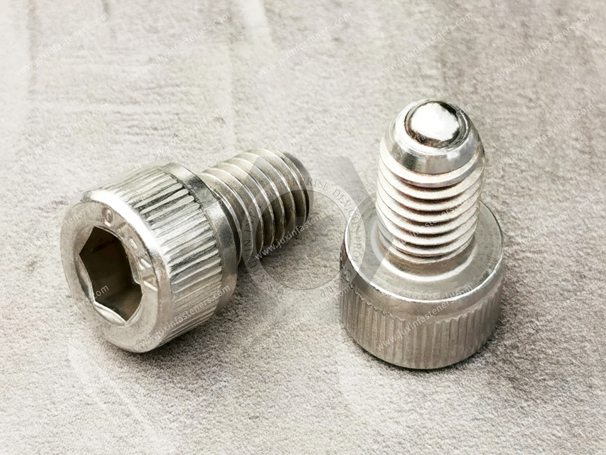
Aluminum extrusion is widely used in:
Automation frames
Machine guards
Workstations
Assembly fixtures
Modular equipment
Spring plungers can provide adjustable positioning between extrusion components and attached mechanisms.
For these applications, engineers should consider:
Aluminum surface marking
Thread strength
Local contact stress
Nose material
Side loading
Repeated adjustment
A softer nose can be considered where protecting the extrusion surface is important.
The mounting thread should also be designed for the actual aluminum structure.
Semiconductor and electronics equipment can contain:
Adjustable modules
Equipment panels
Fixtures
Handling systems
Positioning mechanisms
Service-access components
Spring plungers may provide mechanical positioning where repeatable manual adjustment is required.
For sensitive equipment, the engineer may need to consider:
Particle generation
Surface marking
Material compatibility
Lubrication
Cleanliness requirements
Corrosion
Repeated cycling
The spring plunger should be specified according to the actual equipment environment rather than assuming that a standard industrial component is automatically suitable for clean manufacturing environments.
Spring-loaded positioning hardware can also be used in selected:
Laboratory equipment
Diagnostic equipment
Medical equipment structures
Instrument fixtures
Adjustable mechanisms
For these applications, material, surface condition, cleaning requirements and regulatory/customer specifications should be reviewed carefully.
The use of a spring plunger in medical equipment does not by itself imply medical-device certification.
The final component specification should follow the equipment manufacturer's requirements.
Aerospace and transportation equipment can require lightweight, compact positioning mechanisms.
Potential applications include:
Access panels
Adjustable fixtures
Equipment modules
Control mechanisms
Service components
Positioning systems
Material selection should consider:
Mechanical requirements
Weight
Corrosion
Temperature
Vibration
Applicable customer standards
For regulated or safety-critical applications, the applicable customer and industry qualification requirements should be established before production.
Spring plungers are primarily designed around axial movement.
However, real assemblies can introduce lateral forces.
Side loading can occur because of:
Misalignment
Workpiece movement
Fixture deflection
Vibration
Improper hole geometry
Operator loading
Side loading can increase:
Friction
Pin wear
Body wear
Actuation force
Surface damage
For high-cycle applications, the plunger should therefore not be used as a substitute for a properly designed locating system if substantial lateral loads are present.
Where high positioning loads exist, the surrounding structure should carry the primary structural load whenever possible.
High-cycle applications require attention to contact and wear.
Potential contributors include:
Similar metallic contact pairs
Surface condition
Misalignment
Contamination
Excessive side load
High actuation frequency
Insufficient lubrication where lubrication is permitted
A practical design strategy includes:
Appropriate material selection
Correct alignment
Suitable surface finish
Controlled operating conditions
Correct nose geometry
Maintenance planning
A supplier should not claim that one universal coating or surface treatment eliminates galling in every application.
The correct approach is to evaluate the actual contact system.
Stroke is the distance the plunger can move between its operating positions.
The required stroke should provide sufficient clearance for the mating component.
If the stroke is too short:
The pin may not fully disengage
Workpiece movement may be restricted
Setup may become difficult
If the stroke is unnecessarily long:
Additional installation space may be required
The component may have a larger envelope
Operator movement may increase
Therefore, the stroke should be selected based on the actual clearance requirement.
Machine designers often work with limited installation space.
The required envelope can include:
Threaded body
Knob
Retracted pin
Operator clearance
Adjacent components
Short-body or compact configurations may be considered where installation depth is restricted.
However, a compact body should not be assumed to provide the same stroke, spring characteristics or mechanical capacity as a larger configuration.
The correct comparison should include the complete dimensional envelope and operating requirements.
Spring plungers can be installed in different orientations depending on the mechanism.
Potential orientations include:
Horizontal
Vertical
Angled
Orientation can influence the effect of gravity, contamination and the mating component's movement.
For vertical installations, the engineer should consider whether the plunger's own weight and the direction of the mating load affect engagement.
The surrounding design should prevent the plunger from becoming the unintended primary structural support where loads exceed its intended function.
Industrial machinery may expose positioning mechanisms to vibration.
Potential effects include:
Unintended movement
Fretting
Wear
Noise
Reduced engagement
Where vibration is significant, the engineer should evaluate:
Spring force
Engagement depth
Contact geometry
Direction of vibration
Mating-hole geometry
Required retention force
A spring plunger should not automatically be treated as a vibration-proof locking device.
If the assembly requires positive mechanical locking under vibration, an additional locking mechanism may be appropriate.
This distinction is especially important in machinery design.
A spring plunger can provide:
Positioning
Indexing
Retention
Manual release
It should not automatically replace:
Structural bolts
High-strength screws
Load-bearing pins
Safety locking mechanisms
Where structural loads are significant, the primary load path should be designed using the appropriate mechanical components.
JUXIN FASTENERS also supplies high-strength bolts and nuts for applications where higher mechanical fastening requirements apply.
| Feature | Conventional Screw/Bolt | Retractable Spring Plunger |
|---|---|---|
| Primary function | Clamping | Positioning / indexing |
| Manual retraction | No | Yes |
| Spring return | No | Yes |
| Repeated adjustment | Requires loosening/removal | Designed for repeated operation |
| Tool-free operation | Usually no | Typically possible |
| Typical use | Permanent or semi-permanent fastening | Positioning and quick release |
| Structural load | Application-dependent | Generally not a substitute for structural fastening |
| Maintenance | Fastener removal | Manual engagement/retraction |
The distinction helps engineers choose the correct component for the actual function.
Modular manufacturing equipment frequently requires rapid adjustment.
Potential applications include:
Adjustable fixtures
Modular tooling
Workstations
Inspection stations
Assembly cells
Machine accessories
A retractable indexing plunger can provide repeatable mechanical positions without requiring a loose removable fastener.
This can simplify operator interaction and reduce the number of separate hardware pieces involved in repeated adjustments.
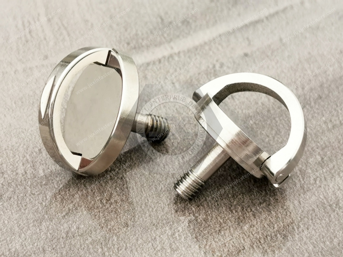
Packaging and material-handling equipment may require adjustable guides, stops and mechanisms.
Spring plungers can be considered for:
Adjustable guide rails
Positioning stops
Changeover mechanisms
Guard adjustment
Fixture indexing
In high-cycle systems, the engineer should evaluate the number of operating cycles and the potential effects of dust, debris and misalignment.
A component suitable for occasional manual adjustment may not have the same suitability for continuous automated cycling.
Procurement should avoid using only a generic description such as:
“Stainless steel spring plunger.”
A production RFQ should define the functional requirements.
Important specifications can include:
Part number
Drawing number
Drawing revision
Thread size
Thread pitch
Body length
Overall length
Stroke
Extended length
Retracted length
Spring force
Nose geometry
Nose diameter
Nose material
Body material
Knob material
Locking function
Finish
Operating environment
Quantity
Packaging
Inspection requirements
This gives suppliers a clear technical basis for quotation.
Where spring force is important, procurement should define how the force is measured.
For example, the specification may identify:
Force at initial position
Force at a defined stroke
Maximum working force
Stroke tolerance
This is more meaningful than simply specifying a nominal spring size.
The supplier and customer should agree on the measurement position and method when force is a critical characteristic.
Inspection can include both dimensional and functional characteristics.
Potential inspection items include:
Thread dimensions
Body diameter
Body length
Overall length
Pin diameter
Pin extension
Knob dimensions
Plunger movement
Retraction
Return action
Locking function where applicable
Spring force
Stroke
Surface condition
Finish
Visible defects
The exact inspection plan should follow the customer drawing and agreed quality requirements.
OEM customers may require documentation covering:
Material designation
Applicable standard
Mechanical properties
Certificate of Conformance
Inspection results
Surface treatment where applicable
Lot identification
Packaging identification
For projects involving regulated industries or customer-specific compliance requirements, documentation should be defined before production.
This avoids the common procurement problem of discovering additional documentation requirements after manufacturing is complete.
Spring plungers may be specified using a combination of product geometry, material requirements and customer standards.
Depending on the product and application, engineers may reference:
ISO
DIN
ASME
ASTM
EN
SAE
Customer-specific engineering standards
Not every spring plunger dimension is governed by one universal standard.
For custom or application-specific designs, the customer's drawing should remain the controlling technical document.
This is especially important for:
Non-standard travel
Custom nose geometry
Special materials
Custom knobs
Modified spring characteristics
Application-specific mounting dimensions
Supplier qualification should evaluate more than unit price.
Relevant areas include:
Can the supplier manufacture the specified:
Body
Thread
Spring
Plunger
Nose
Knob
Locking mechanism?
Can critical dimensions and functional characteristics be inspected consistently?
Can the specified material and documentation be maintained through production?
Can changes affecting material, dimensions, spring characteristics or production processes be controlled?
Can small mechanical components be packaged in a way that protects threads, knobs and contact surfaces during shipment and handling?
These considerations are particularly important for OEM programs with repeat production.
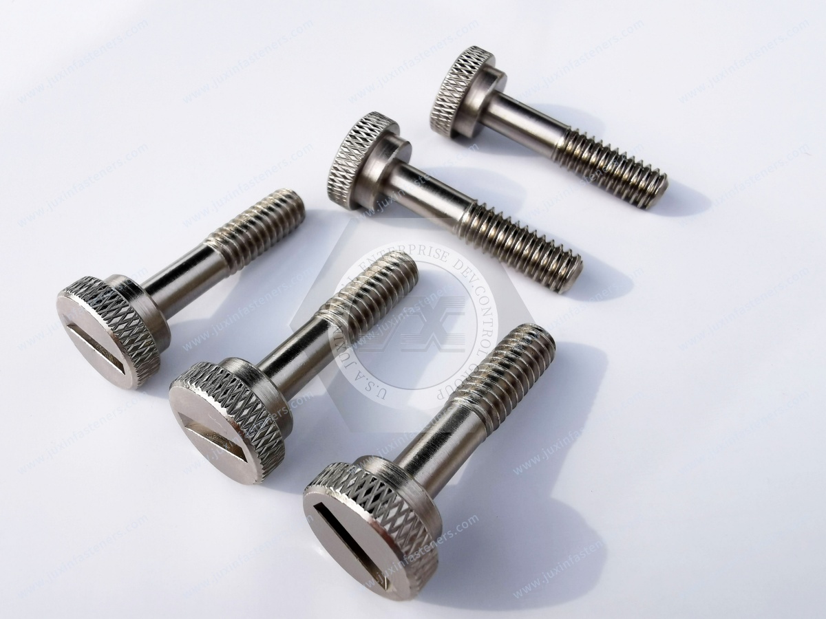
JUXIN FASTENERS can support customer requirements for industrial fastening and positioning components based on available technical information such as:
2D drawings
3D models
Samples
Product specifications
Application photographs
Material requirements
Dimensional requirements
Functional requirements
Custom requirements may include:
Special body lengths
Non-standard threads
Special nose materials
Customized nose geometry
Modified knob configurations
Application-specific spring characteristics
Special finishes
Custom design requirements should be evaluated against manufacturability, application conditions and required production quantities.
JUXIN FASTENERS provides industrial fastening and mechanical component solutions for OEM applications, including positioning and indexing hardware.
Relevant solution areas include:
Knob-grip retractable spring plungers
Indexing plungers
Retractable positioning pins
Twist-to-lock spring plungers
Threaded spring plungers
Compact positioning hardware
Steel spring plungers
Stainless steel spring plungers
Brass-nose configurations
Acetal/POM-nose configurations
Application-specific positioning components
Custom mechanical fastening components
Selection can be based on:
Thread + Stroke + Spring Force + Nose Geometry + Nose Material + Body Material + Locking Function + Environment
This approach helps engineers and procurement teams move from a generic spring-plunger description to a production-ready specification.
Spring plungers often work alongside conventional fastening components rather than replacing them.
An industrial assembly may combine:
Spring plungers
Machine screws
Bolts
Nuts
Self-clinching fasteners
Rivet nuts
Threaded components
Custom machined parts
Each component performs a different function.
A spring plunger may provide positioning.
A bolt may provide structural clamping.
A self-clinching nut may provide permanent internal threading in sheet metal.
A CNC-machined component may provide a custom interface.
For broader industrial fastening requirements, JUXIN FASTENERS also provides industrial and automotive bolts and nuts.
A strong spring-plunger specification starts with the mechanical function.
Instead of asking only:
“Which spring plunger do we need?”
the engineering team should ask:
“What must the plunger accomplish?”
For example:
How accurately must the mechanism locate?
How much force is required to prevent unintended disengagement?
How far must the pin move to clear the mating feature?
How frequently will operators retract the plunger?
Will the component encounter moisture, dust, chemicals or elevated temperature?
How many operating cycles are expected?
These answers provide a much better basis for component selection.
Another commonly overlooked factor is the receiving feature.
A spring plunger cannot provide reliable indexing if the mating hole is poorly designed.
Important characteristics include:
Hole diameter
Hole depth
Edge condition
Chamfer
Position
Alignment
Material
Surface condition
The entry geometry should allow the plunger nose to engage without unnecessary impact or interference.
For a cylindrical plunger pin, the receiving hole should provide sufficient clearance for reliable engagement while maintaining the required positioning function.
Therefore:
Spring Plunger + Mating Hole + Supporting Structure
should be considered one positioning system.
In high-cycle automation, simply selecting a stronger spring plunger does not automatically guarantee longer service life.
Actual life can be influenced by:
Number of cycles
Side loading
Alignment
Contact material
Surface finish
Contamination
Spring stress
Actuation speed
Installation rigidity
Maintenance
For this reason, high-cycle applications should be evaluated using the complete mechanism.
Where cycle life is a critical customer requirement, the expected operating conditions should be communicated during RFQ development.
For an OEM RFQ, provide as much of the following information as possible:
Plunger type
Thread
Body diameter
Body length
Overall length
Stroke
Pin diameter
Nose geometry
Knob dimensions
Initial force
Working force
Force at defined stroke
Required return behavior
Body material
Pin material
Nose material
Spring material where specified
Knob material
Positioning
Indexing
Retention
Manual release
Twist-to-lock
Repeated changeover
Machinery
Automation
Fixture
Workholding
Electronics
Transportation
Laboratory
Other industrial equipment
Indoor
Outdoor
Humidity
Dust
Chemicals
Temperature
Clean manufacturing environment
Prototype quantity
Annual volume
Order quantity
Packaging
Delivery requirements
Drawing revision
Inspection requirements
CoC
Material documentation
Functional testing requirements
A practical development path is:
Positioning Requirement
↓
Required Engagement
↓
Load and Retention Requirement
↓
Stroke
↓
Spring Force
↓
Thread and Mounting
↓
Nose Geometry
↓
Nose Material
↓
Locking Function
↓
Environment
↓
Cycle Requirement
↓
Inspection
↓
Documentation
↓
Supplier Qualification
↓
Production RFQ
This process connects engineering design with procurement requirements.
It also reduces the risk of selecting a component based only on a nominal thread size.
A supplier can quote more accurately when the application is clearly defined.
For example, these two requests are technically different:
“M8 stainless spring plunger.”
and:
“M8 stainless retractable indexing plunger, 6 mm working stroke, reusable manual operation, rounded nose, installed in an aluminum fixture, outdoor environment.”
The second specification provides significantly more information for engineering evaluation.
This reduces ambiguity and helps procurement compare supplier quotations on the same technical basis.
Spring plungers are often only one part of a larger equipment development program.
An OEM may also require:
Custom screws
Bolts
Nuts
Washers
Self-clinching fasteners
Rivet nuts
CNC-machined components
Stainless steel components
High-strength fasteners
Plastic fastening components
JUXIN FASTENERS supports multiple industrial fastening categories so that related components can be evaluated according to the same application and procurement requirements.
For plastic equipment and lightweight assemblies, customers can also review the automotive plastic fasteners solution for examples of plastic fastening applications.
JUXIN FASTENERS works with industrial customers requiring application-specific fastening and mechanical components.
For spring plunger projects, the sourcing process can begin with:
Drawing
Sample
Product photograph
3D model
Technical specification
Application description
The engineering and procurement discussion can then focus on:
Positioning function
Spring characteristics
Stroke
Thread
Nose material
Body material
Locking function
Operating environment
Quantity
Quality requirements
The objective is to establish a clear production specification before quotation and manufacturing.
If you are sourcing knob-grip retractable spring plungers, indexing plungers, positioning pins or custom spring-loaded positioning hardware for machinery,
automation equipment, fixtures, tooling, workholding systems, electronics equipment, transportation equipment or other OEM applications, JUXIN FASTENERS can review your requirements.
Please provide your 2D drawing, 3D model, sample, product specification or application information where available.
For an efficient RFQ, include:
Plunger type
Thread specification
Body dimensions
Stroke
Spring force
Nose geometry
Nose material
Body material
Locking function
Operating environment
Cycle requirements
Inspection requirements
Documentation requirements
Production quantity
JUXIN FASTENERS
20+ Years of Fastener Experience
Knob-Grip Retractable Spring Plungers, Indexing Hardware and Industrial OEM Fastening Components
Website: www.juxinfasteners.com
Email: info@juxinfasteners.com
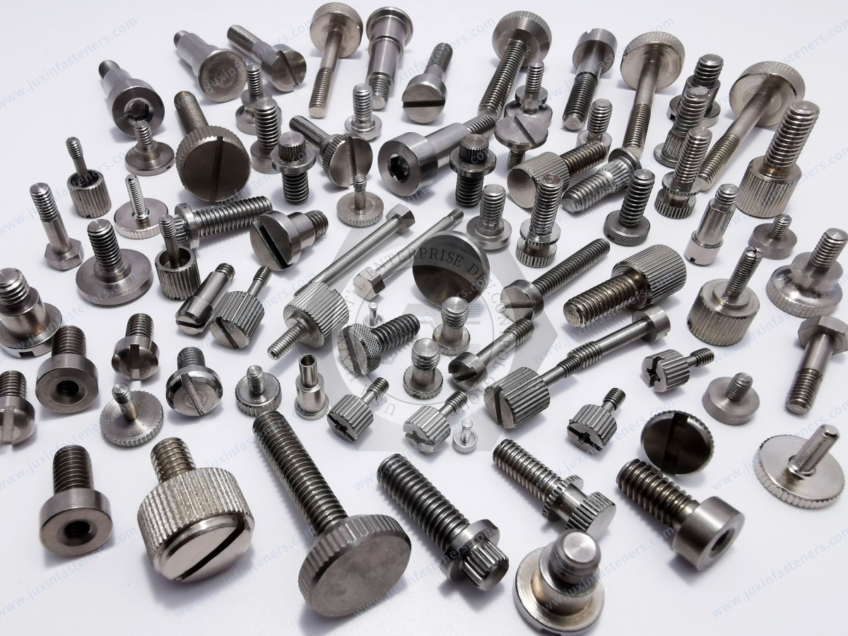
 MORE NEWS

Sep. 25, 2026

Sep. 25, 2026

Sep. 25, 2026
Contact Us
Tel.:
+86 020 8621 0320
+86 020 3121 6067
E-mail:
Technical Support:
Navigation
SEND INQUIREY