
Call Us
+86 136 6007 9809
Call Us
+86 136 6007 9809

Oct. 25, 2023
Spring clip nuts are formed fastening components used to position and retain a screw-engagement feature on sheet-metal panels, flanges and brackets.
Depending on the geometry and industry terminology, related products may be described as:
spring clip nuts
spring nuts
leaf spring nuts
U-clip nuts
U-nuts
panel clip nuts
floating clip nuts
sheet metal spring nuts
Their value is not simply that they replace a conventional nut.
A properly selected spring clip nut can solve several assembly problems simultaneously:
Panel Retention + Thread Positioning + Assembly Access + Tolerance Accommodation + Production Efficiency
For design engineers and procurement teams, however, the spring behavior of the component must be considered together with panel geometry, thread location, screw specification and operating environment.
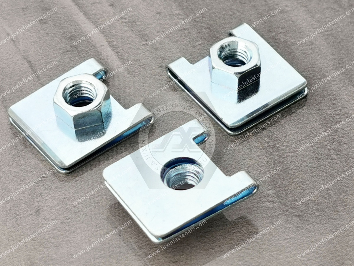
A spring clip nut normally uses a formed metal body that elastically engages a panel or flange.
The component is installed onto the designed panel feature and retained in position before the mating screw is assembled.
Depending on the design, the screw may engage:
a formed thread
an extruded thread
a threaded barrel
a retained threaded element
another engineered screw-engagement feature
The spring section and the threaded section perform related but different functions.
A useful engineering model is:
Spring Feature → Retains and Positions the Clip
Thread Feature → Engages the Screw
Panel → Supports the Clip
Screw Joint → Generates Final Clamp Load
These functions should not be treated as interchangeable.
This distinction is important.
The spring force of the clip helps retain the fastener on the panel before or during assembly.
Once the screw is tightened, the final joint behavior depends on the complete fastening system.
Therefore:
Clip Retention Force ≠ Final Joint Clamp Load
A spring clip that grips the panel strongly does not automatically mean that the completed screw joint has higher load capacity.
Likewise, increasing spring force is not automatically an improvement.
Excessive spring force may create:
difficult installation
panel marking
coating damage
clip deformation
inconsistent assembly force
The spring geometry must be matched to the panel and manufacturing process.
The spring portion of a clip nut is designed around a specific panel condition or grip range.
If the panel is too thin for the selected clip, possible problems include:
insufficient retention
clip movement
poor positioning
reduced assembly consistency
If the panel is too thick, possible problems include:
excessive installation force
permanent clip deformation
panel or coating damage
incorrect thread position
difficulty seating the clip completely
For this reason, an OEM RFQ should include:
nominal panel thickness
panel-thickness tolerance
coating condition where relevant
Thread size alone does not define the correct spring clip nut.
Grip range describes the panel-thickness condition that a particular clip geometry is intended to accommodate.
The actual allowable range is product-specific.
It should not be assumed from appearance.
Two spring clip nuts with the same M5 or M6 thread may have different:
grip ranges
reach dimensions
spring geometry
thread locations
installation forces
They may therefore be unsuitable as direct replacements for one another.
For an edge-mounted spring clip nut, the relationship between the panel edge and screw centerline is critical.
A simplified design relationship is:
Panel Edge → Clip Reach → Screw Centerline
If the reach is incorrect, the screw may not align with the mating thread.
Possible symptoms include:
difficult screw starting
angled screw entry
cross-threading
clip displacement
assembly-line rejection
For sample matching or second-source development, reach should therefore be measured and controlled.
Not every clip nut locates the thread in the same way.
Some designs position the threaded feature relatively rigidly.
Others provide controlled movement to accommodate assembly tolerances.
A fixed design is useful when:
screw position is accurately controlled
precise thread location is required
panel tolerances are relatively tight
A floating design may be useful when:
several panels must align
stamped components accumulate tolerances
the mating screw position varies slightly
assembly needs controlled positional accommodation
This makes floating spring nuts valuable in some automotive, enclosure and industrial assemblies.
A floating threaded element has a designed movement range.
It is not intended to correct unlimited hole-position error.
If the assembly requires more movement than the fastener can accommodate, the screw may:
contact the edge of the hole
enter the thread at an angle
push the clip out of position
cross-thread
create abnormal loading
The allowable movement should therefore be validated for the specific component.
Sheet-metal assemblies often contain multiple dimensional contributors:
Panel A Tolerance
Panel B Tolerance
Hole Position Tolerance
Bracket Tolerance
Assembly Position Variation
A rigid threaded location may make final assembly difficult when these tolerances accumulate.
A controlled floating feature can provide assembly accommodation without requiring every component to align perfectly at nominal position.
This is a tolerance-management function—not an excuse for uncontrolled manufacturing variation.
Both technologies can provide some alignment accommodation, but their structures differ.
A cage nut generally consists of a nut captured within a spring cage and is installed into a compatible panel opening.
A spring clip nut generally uses a clip geometry that engages an edge or other designed panel feature.
Therefore:
Spring Clip Nut → Clip-to-Panel Retention
Cage Nut → Captured Nut in Cage / Panel Opening
The correct choice depends on:
panel geometry
installation direction
access
load
required floating movement
serviceability
A rivet nut is installed into a prepared hole and mechanically set into the panel.
A spring clip nut normally attaches without a rivet-nut setting operation.
panel-edge access is available
rapid installation is important
mechanical clipping is preferred
controlled alignment accommodation may be useful
the fastening point is away from the edge
blind-side threaded installation is required
the application needs an installed threaded insert
setting equipment is acceptable
The two technologies solve different sheet-metal fastening problems.
Weld nuts become permanently attached through a controlled welding process.
Spring clip nuts use mechanical retention.
A spring clip may be useful when:
welding is undesirable
installation occurs late in production
replaceability is beneficial
heat input must be avoided
A weld nut may be more appropriate where a permanently welded threaded feature is required and the manufacturing process supports it.
Selection should follow the complete assembly architecture.
Self-clinching nuts are mechanically pressed into properly prepared sheet material.
They can provide a captive threaded feature without welding, but they require:
suitable panel material
controlled hole geometry
compatible sheet thickness
installation force and tooling
Spring clip nuts follow another installation principle and may be preferable where edge attachment and rapid clipping fit the production process.
Not automatically.
The spring action that holds the clip to the panel should not be confused with a validated screw-locking system.
Screw loosening behavior depends on factors including:
joint design
clamp load
screw specification
mating thread
tightening process
vibration
thermal cycling
joint stiffness
A spring clip nut may be suitable for vibration-exposed equipment, but the complete joint must be evaluated.
When engineers discuss vibration and clip nuts, three different retention mechanisms may be involved.
This is clip-to-panel retention.
This involves the interaction between the clip, panel and completed joint.
This is a threaded-joint loosening question.
These are not the same engineering problem.
Separating them helps avoid incorrect product claims and incorrect testing.
Applications exposed to shock or vibration should be evaluated under representative service conditions.
Potential concerns include:
clip movement
panel deformation
thread movement
screw loosening
wear at the panel interface
coating damage
For critical applications, functional testing may be required rather than relying solely on catalog descriptions.
Spring clip nuts require materials capable of supporting the intended forming and elastic behavior.
Depending on the design and specification, materials may include:
carbon spring steels
alloy spring steels
stainless spring materials
other engineered strip materials
Material selection should consider:
required spring behavior
forming process
fatigue requirements
corrosion environment
temperature
coating process
cost
A generic local material designation should not be used as a universal specification for global OEM sourcing.
Two components manufactured to similar dimensions can behave differently if their material condition differs.
Important variables may include:
material chemistry
strip condition
heat treatment where applicable
hardness where specified
forming history
These factors can influence:
spring recovery
installation force
retention behavior
permanent deformation
fatigue performance
For second-source development, dimensional copying alone may therefore be insufficient.
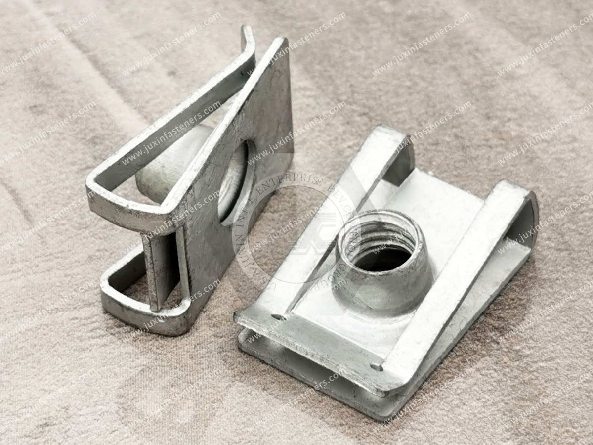
No.
A single hardness value should not be applied to every spring clip nut.
The required hardness or mechanical condition depends on:
material
geometry
manufacturing route
spring requirement
customer specification
Where hardness is a controlled characteristic, it should come from the applicable drawing or approved product specification.
Surface treatment should be selected according to the service environment and customer requirement.
Possible coating systems for steel components may include appropriate:
zinc-based coatings
zinc-alloy systems
phosphate-based treatments
organic or topcoat systems
other customer-specified finishes
Stainless spring materials may be used in suitable applications where corrosion requirements justify them.
However:
Finish Color ≠ Corrosion Performance
and
Coating Name ≠ Complete Coating Specification
When corrosion resistance matters, procurement should specify the required performance rather than simply asking for “zinc plated.”
Useful information may include:
service environment
customer coating specification
corrosion test requirement where applicable
restricted-substance requirements
appearance requirement
mating-material considerations
This provides a more reliable basis for supplier qualification.
For spring clips, surface treatment is not only a corrosion issue.
Coating buildup can affect:
panel grip
dimensional fit
thread condition
installation force
This becomes more important in small or tightly controlled components.
Coating should therefore be considered as part of the finished-component specification.
If a clip does not remain on the panel before final assembly, possible causes include:
incorrect grip range
wrong panel thickness
incorrect clip geometry
insufficient spring retention
permanent deformation
panel edge variation
installation damage
Do not immediately assume that a “stronger spring” is the solution.
First verify the interface.
Possible causes include:
panel too thick
incorrect grip range
excessive spring force
coating buildup
burrs
incorrect installation direction
wrong component
Excessive installation force can reduce production efficiency and may damage the part.
Check:
reach dimension
hole location
clip seating
panel tolerance
floating range where applicable
part number
clip deformation
This is often an interface problem rather than a thread-manufacturing problem.
Potential contributors include:
thread misalignment
incorrect screw
damaged thread
excessive positional error
screw entering at an angle
clip movement during assembly
A floating design may help with controlled tolerance variation, but it cannot correct every assembly error.
Possible causes include:
panel outside the intended grip range
excessive installation deformation
incorrect material condition
wrong clip geometry
damage during handling
A permanently opened clip may no longer provide its intended pre-assembly retention.
Sliding a spring clip over a coated panel can create contact and friction.
Potential considerations include:
clip-edge geometry
installation force
panel coating
burr condition
surface finish
assembly method
Where cosmetic appearance or corrosion protection is critical, panel/clip interaction should be evaluated during validation.
Investigate:
panel retention
clip geometry
thread alignment
screw entry
tightening process
panel deformation
whether the selected fastener architecture is suitable
Increasing tightening torque is not an appropriate general correction for a poorly retained clip.
There is no universal reuse rule.
A removed clip may have experienced:
permanent spring deformation
coating damage
thread wear
corrosion
installation damage
For serviceable equipment, reuse should follow the OEM maintenance requirement or validated product specification.
Where the component is specified as single-use, it should be replaced.
Spring clip nuts are often stamped and formed components.
Production control may involve:
strip-material consistency
stamping accuracy
forming control
tooling condition
heat treatment where required
thread formation
surface treatment
dimensional inspection
functional inspection
For high-volume programs, consistency can be as important as nominal dimensions.
A small change in formed geometry can influence:
panel grip
installation force
thread position
spring recovery
Therefore, supplier evaluation should consider the manufacturing process rather than only the final appearance.
This is particularly important for:
automotive programs
automated assembly
large annual volumes
tight panel tolerances
second-source qualification
Automotive assemblies frequently use clip-style fastening components where fast installation and panel integration are important.
Potential applications can include suitable:
body-panel assemblies
brackets
trim systems
interior structures
underbody covers
HVAC assemblies
electrical brackets
service panels
Actual selection depends on the vehicle program and customer specification.
Automotive body and trim assemblies may involve multiple stamped, molded and formed components.
Controlled floating capability can help accommodate appropriate positional variation between:
body panels
brackets
trim
covers
mating holes
This can improve assembly robustness when designed correctly.
It should not replace proper dimensional control.
Spring clip nuts may be used in suitable:
electrical cabinets
control enclosures
switchgear
power distribution equipment
UPS equipment
industrial electronics housings
They can support removable covers and other sheet-metal assemblies where quick screw installation is beneficial.
Grounding and electrical-bonding requirements must be evaluated separately.
Potential applications include:
equipment housings
fan assemblies
service panels
sheet-metal covers
brackets
thermal-management equipment
Selection should consider:
vibration
moisture
corrosion
temperature
service access
panel thickness
Clip nuts can be useful for:
machine guards
access covers
electrical cabinets
brackets
sheet-metal housings
Where equipment is frequently serviced, maintenance requirements should be included in fastener selection.
Outdoor and mobile equipment can expose fasteners to:
vibration
impact
moisture
dirt
corrosion
repeated service
The clip, coating, panel and screw joint should therefore be evaluated as a system.
A practical engineering sequence is:
1. Define Panel Thickness
↓
2. Define Panel Edge / Mounting Geometry
↓
3. Define Screw Centerline / Reach
↓
4. Define Thread or Screw Type
↓
5. Determine Fixed or Floating Requirement
↓
6. Define Installation Direction
↓
7. Define Load and Vibration Environment
↓
8. Define Material and Corrosion Requirement
↓
9. Prototype the Assembly
↓
10. Validate Before Production
This approach is more reliable than selecting a clip from thread size alone.
Ask:
Does the screw location have meaningful positional variation?
If no:
→ A fixed threaded clip may be appropriate.
If yes:
→ Determine how much controlled movement is actually required.
Then evaluate:
floating clip nut
cage nut
another fastening architecture
The required movement should be defined rather than assumed.
Consider another technology when:
the fastening point is far from a panel edge
high structural loads require another retention method
permanent captive attachment is required
sealing is required at the fastening point
installation geometry does not permit clipping
the panel cannot support the clip geometry
Possible alternatives include:
rivet nuts
weld nuts
self-clinching nuts
cage nuts
threaded inserts
conventional nut-and-bolt joints
The objective is to select the fastening architecture that matches the assembly.
For a spring clip nut, a visually accurate dimensional copy can still perform differently.
A robust second-source evaluation should consider:
Geometry + Material + Material Condition + Spring Behavior + Thread + Coating + Panel Fit + Screw Assembly
This is particularly important when replacing an existing automotive or industrial production component.
When a drawing is unavailable, provide:
original spring clip nut
mating screw
panel sample if possible
panel thickness
photographs of the assembly
annual usage
known installation or quality problems
A panel sample can be especially valuable because spring-clip performance is closely related to the actual panel interface.
For standard spring clip nuts, provide:
product type
thread size
panel thickness
reach
fixed or floating requirement
material
finish
quantity
annual demand
For custom drawing-controlled spring fasteners, provide:
2D drawing
3D model where useful
panel drawing
dimensions and tolerances
thread specification
material
mechanical requirements where specified
finish
inspection requirements
sample quantity
annual forecast
For second-source projects, also provide:
existing part number
physical sample
mating screw
panel sample
application information
current failure issue, if any
Instead of asking only:
“Can you make this clip nut?”
procurement and supplier-development teams can ask:
How will panel fit be verified?
How is spring geometry controlled?
How is the thread inspected?
How is material condition controlled?
How is coating controlled?
Can sample assembly be evaluated with our panel and screw?
What characteristics are treated as critical?
How are production changes controlled?
These questions provide more useful supplier information than a simple unit-price comparison.
For broader design decisions, review related JUXIN FASTENERS resources on:
Clip-On Nuts for Sheet Metal
U-Nuts for Sheet Metal
Floating Clip Nuts
Automotive Panel Fasteners
Cage Nuts
Speed Nuts
Blind Rivet Nuts
Weld Nuts
Self-Clinching Nuts
Custom Stamped Fasteners
Each technology solves a different fastening problem.
JUXIN FASTENERS supplies standard and custom fastening components for global industrial OEM applications.
Our related capabilities include:
spring clip nuts
U-nuts
U-clip nuts
panel nuts
floating clip nuts
automotive clip fasteners
sheet-metal fastening components
custom stamped fasteners
cage nuts
weld nuts
rivet nuts
self-clinching fasteners
For an existing product, send:
Sample / Drawing → Thread → Panel Thickness → Reach → Material → Finish → Quantity
For a new design, send:
Panel → Fastening Position → Thread → Alignment Requirement → Environment → Quantity
For a second-source project, send:
Existing Fastener → Panel → Screw → Application → Existing Problem → Annual Demand
JUXIN FASTENERS can support drawing review, sample matching, panel-fit evaluation,
custom stamped fastener development and volume production sourcing for automotive and industrial OEM programs.
Email: info@juxinfasteners.com
Website: www.juxinfasteners.com
 MORE NEWS

Sep. 27, 2026

Sep. 27, 2026

Sep. 27, 2026
Contact Us
Tel.:
+86 020 8621 0320
+86 020 3121 6067
E-mail:
Technical Support:
Navigation
SEND INQUIREY