
Call Us
+86 136 6007 9809
Call Us
+86 136 6007 9809

Oct. 25, 2023
Clip-on nuts, U-nuts, spring nuts, and threaded clip nuts can provide an efficient way to create threaded attachment points on sheet-metal panels,
brackets, housings, and equipment structures. However, seemingly simple installation problems can create significant production issues.
A clip that falls off before final assembly, a screw that will not start smoothly, excessive push-on force, cross-threading, or inconsistent thread alignment may indicate more than a defective fastener.
In many cases, the actual cause is an interface mismatch between the clip-on nut, panel, coating, hole location, mating screw, and assembly process.
For design engineers, manufacturing engineers, quality teams, and supplier-development professionals,
identifying the real failure mechanism before changing the fastener can reduce unnecessary part revisions and repeated supplier trials.
This guide explains how to troubleshoot common clip-on nut installation problems and what information should be evaluated when developing a replacement or second source.
A typical clip-on nut combines a spring-style body with a threaded feature.
The clip portion positions and retains the fastener on the panel before and during assembly. The threaded feature receives the mating screw.
This distinction matters because a clip-on nut should not automatically be treated as a universal vibration-locking device.
Depending on the design, the spring geometry may influence retention and assembly behavior, but final joint performance depends on the complete fastening system, including:
Clip geometry
Panel thickness
Panel material
Thread engagement
Mating screw
Joint geometry
Clamp conditions
Surface finishes
Installation process
Service loading
Vibration environment
If resistance to vibration loosening is a critical requirement, the assembled joint should be validated under representative service conditions.
One common production complaint is:
“The clip installs, but it does not stay on the panel before the screw is inserted.”
The immediate reaction may be to request a clip with greater spring force. That is not always the correct solution.
Possible causes include:
Panel thinner than the intended grip condition
Clip opening too large for the panel
Incorrect spring geometry
Panel edge geometry mismatch
Clip deformation
Dimensional variation
Surface finish affecting retention
Incorrect replacement part
Installation damage
More retention is not automatically better.
A more aggressive spring geometry can also increase installation force, damage coatings, deform thin panels, or make automated assembly less consistent.
The engineering objective should therefore be:
sufficient retention for the assembly process without creating unacceptable installation force or panel damage.
That balance should be evaluated using the actual finished panel.
Another frequent issue occurs when operators need excessive force to push the clip onto the panel.
Possible causes include:
Panel thickness above the intended range
Paint or powder coating increasing effective thickness
Clip opening too small
Spring geometry mismatch
Burrs or irregularities on the panel edge
Nearby formed features interfering with installation
Material or forming variation
Suppose the drawing identifies a nominal sheet thickness but the production panel receives a surface treatment.
The clip interacts with the finished interface, not the raw sheet specification alone.
Depending on the assembly, paint, coating, plating, sealant, overlapping layers, or other surface conditions can alter the effective grip condition.
For this reason, troubleshooting should include measurements and trial installation using representative production panels.
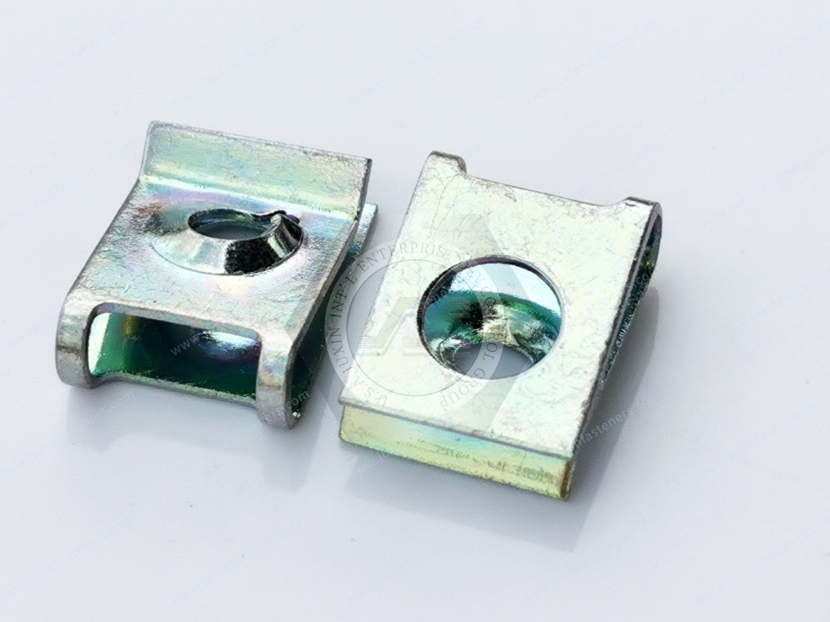
A clip may fit the panel correctly while the threaded feature still fails to align with the screw path.
This is often a geometry problem.
Important variables include:
Edge-to-hole-center distance
Clip reach
Panel-hole position
Thread-center location
Clip seating position
Hole or slot geometry
Nearby bends
Component stack-up
If the reach is too short or too long, the nut thread may sit off-center relative to the panel hole.
The screw may then contact the edge of the threaded feature rather than entering axially.
Small alignment errors can become larger manufacturing problems when screws are installed rapidly or with powered assembly equipment.
Symptoms can include:
Difficulty starting the screw
Increased assembly time
Screw entering at an angle
Cross-threading
Thread damage
Operator rework
Inconsistent assembly behavior
When these problems occur, engineers should examine the full dimensional chain rather than evaluating thread size alone.
Cross-threading is sometimes blamed immediately on the nut thread.
Thread quality should certainly be checked, but cross-threading can also originate elsewhere in the assembly.
Possible contributors include:
Screw entering at an angle
Nut thread not centered with the access hole
Clip movement during screw insertion
Incorrect screw or thread specification
Damaged mating screw
Insufficient alignment between assembled components
Excessive positional tolerance
Assembly tooling or screw presentation
Before changing the clip-on nut design, check:
Does the mating screw match the specified thread?
Can the screw enter the nut axially?
Is the nut center aligned with the panel hole?
Does the clip move during screw engagement?
Does the issue occur with multiple screws?
Does it occur on multiple panels?
Is the problem limited to a particular production batch?
This sequence helps distinguish a fastener issue from a mating-component or process issue.
A clip-on nut that stops before reaching its intended location may create thread misalignment even if the component itself is dimensionally correct.
Check for:
Panel-edge burrs
Local panel deformation
Interference from bends or ribs
Coating buildup
Incorrect insertion direction
Insufficient installation clearance
Clip geometry incompatible with the panel profile
The panel should be evaluated as a three-dimensional interface rather than simply as a thickness value.
Clip-on fasteners typically contact the panel directly, so the relationship between spring geometry and surface treatment deserves attention.
Depending on the application, excessive contact pressure or sliding during installation may mark or damage a coating.
Factors to evaluate include:
Clip edge geometry
Installation force
Panel coating system
Effective panel thickness
Installation direction
Surface condition
Number of installation cycles
If corrosion protection depends on the integrity of the panel coating, installation damage may become more than a cosmetic issue.
The fastener, panel, coating, and installation process should therefore be evaluated as a system.
Some elastic movement is inherent in many spring-style clip designs.
Permanent deformation, however, can indicate that the fastener is being installed outside its intended interface condition.
Potential causes include:
Excessive panel thickness
Incorrect installation method
Interference with panel geometry
Material condition mismatch
Incorrect clip dimensions
Repeated installation beyond what the application has validated
If deformation changes the thread position or panel retention, subsequent screw installation may also be affected.
Depending on the clip design, excessive movement can make screw engagement inconsistent.
Possible causes include:
Insufficient retention on the panel
Incorrect panel thickness
Oversized or incorrectly located panel opening
Incorrect clip geometry
Assembly force pushing the clip out of position
Mismatch between the replacement part and original interface
When evaluating a second-source component, rotational or positional stability should be checked during actual screw installation rather than only during dimensional inspection.
This is a particularly important issue for purchasing and supplier-development teams.
Two clip nuts may share:
The same thread size
Similar overall dimensions
Similar appearance
Similar material description
and still behave differently in production.
Critical differences can exist in:
Clip opening
Spring profile
Clip reach
Thread-center position
Forming radii
Overall height
Material condition
Surface finish
Local contact geometry
This is why sourcing clip-on nuts by photograph and thread size alone can create unnecessary qualification problems.
A fastening problem does not always originate from a single out-of-tolerance dimension.
Consider a simplified assembly involving:
panel edge → clip position → panel hole → mating component hole → screw axis → nut thread
Each feature may be individually acceptable, but their combined variation can reduce the available alignment margin.
This is a tolerance stack-up problem.
For assemblies experiencing intermittent cross-threading or inconsistent screw starting, engineers should examine how positional tolerances accumulate through the entire assembly.
A replacement fastener that changes thread-center position slightly may expose a tolerance-stack problem that was previously hidden.
Panel thickness is one of the first dimensions to verify during troubleshooting.
Do not evaluate only the nominal thickness shown on a material specification.
Consider:
Actual production thickness
Thickness tolerance
Coating
Paint
Multiple sheet layers
Local formed geometry
Burrs
Surface treatments
The effective grip condition at the installation location is what the clip actually experiences.
For edge-mounted U-nuts and clip nuts, clip reach and edge-to-hole-center distance should be evaluated together.
If the nut center does not correspond with the panel-hole center, forcing the screw into engagement can increase the risk of angled entry and thread damage.
For replacement sourcing, these dimensions should be compared directly between:
Original component
Proposed replacement
Actual production panel
This is more reliable than comparing catalog descriptions alone.
Thread identification should be confirmed rather than assumed.
Depending on the application, relevant information may include:
Thread designation
Thread pitch
Mating screw specification
Required thread fit or customer specification
Screw entry geometry
Required engagement
A screw that appears to start correctly may still be incompatible if the thread specification differs.
When an existing part cannot be confidently identified, the drawing and physical sample should be reviewed together.
Material and surface finish can affect both service performance and assembly behavior.
Questions to investigate include:
Has the material changed from the approved part?
Has the surface finish changed?
Does the finish affect effective dimensions?
Is the panel coating different from the qualification condition?
Are mating materials appropriate for the environment?
Has corrosion changed the thread or clip interface?
Where corrosion performance is required, the material and finish should be selected according to the actual environmental conditions and customer specification.
Do not assume that one coating system is universally suitable for every clip-on nut application.
Some clip-on nut applications require service access or repeated disassembly.
However, reusable should not be interpreted as unlimited reuse.
Repeated installation, removal, panel interaction, screw tightening, corrosion exposure, or accidental deformation can change the condition of the fastener.
If repeated service cycles are an important design requirement, the component should be evaluated for the intended maintenance process.
Replacement criteria can also be defined where appropriate.
Automotive applications may combine:
Coated sheet metal
Multiple panel layers
High production volumes
Powered screw installation
Vibration
Temperature variation
Corrosive environments
Tight packaging constraints
As a result, a small dimensional change in a U-nut or clip nut can affect production efficiency.
When investigating an automotive assembly problem, useful information includes:
Original fastener drawing
Production panel
Mating screw
Installation orientation
Assembly sequence
Failure samples
Description of when the failure occurs
The objective should be to reproduce the failure condition rather than inspect the fastener in isolation.
Clip nuts and spring nuts may also be used in:
Electrical cabinets
Power distribution equipment
Control panels
Equipment housings
Industrial automation systems
Data center equipment structures
In these applications, enclosure alignment, panel coatings, service access, corrosion conditions, and equipment-specific electrical requirements may all influence fastener selection.
A replacement fastener should therefore be reviewed against the actual equipment requirements rather than selected solely by mechanical dimensions.
HVAC housings, machinery covers, guards, access panels, brackets, and commercial equipment can use clip-on nuts where rapid assembly and service access are useful.
Common troubleshooting concerns include:
Clips lost during production
Excessive installation force
Misaligned service screws
Damaged panel coatings
Replacement clips that do not match legacy panels
Legacy equipment deserves particular attention because drawings, production methods, or coating systems may have changed over time.
When an assembly problem is identified, changing the fastener is not automatically the best engineering response.
Consider three possibilities:
This may be appropriate when the existing panel geometry is fixed and a custom or revised clip can better match the interface.
For a new design, changing hole location, edge geometry, clearance, or panel thickness may create a more robust assembly.
If the panel edge is difficult to access, retention is inadequate, or the application requirements have changed, another fastening technology may deserve consideration.
Possible alternatives include:
Cage nuts
Self-clinching fasteners
Rivet nuts
Weld nuts
These are different fastening technologies and should be selected according to panel geometry, access, manufacturing process, loading, and service requirements.
If positional adjustment is a primary requirement, some cage-nut architectures may offer movement of the retained nut within the cage.
That does not make a cage nut automatically superior to a clip nut.
The engineer should compare:
Panel preparation
Edge access
Hole geometry
Positional adjustment
Installation method
Packaging space
Service requirements
The correct technology depends on the assembly architecture.
A clip-on nut generally requires an appropriate panel edge or mounting geometry.
A rivet nut is installed through a prepared hole and can provide a threaded attachment where backside access is unavailable.
If an engineer is repeatedly struggling to package an edge-mounted clip, the underlying issue may be fastening-technology selection rather than clip dimensions.
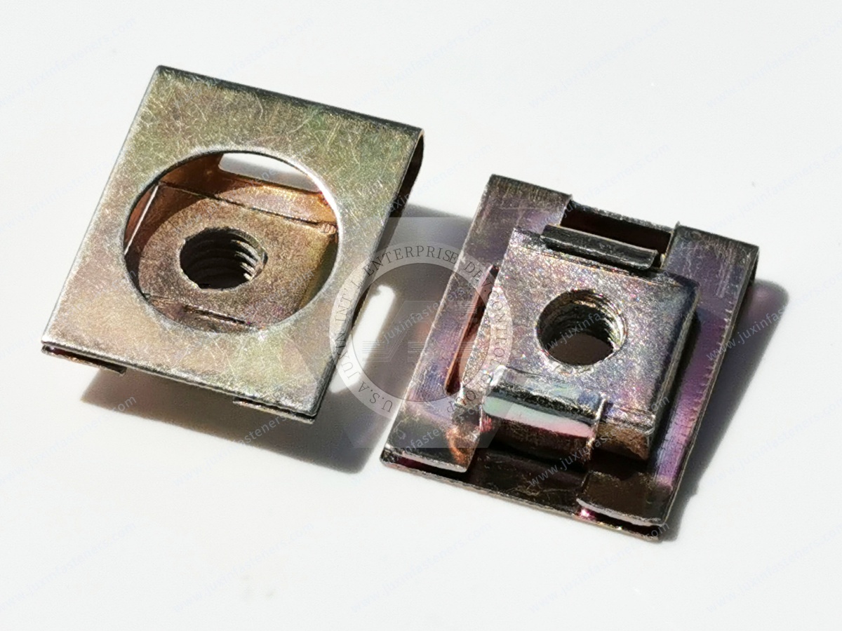
A self-clinching fastener is installed into suitable sheet material using a controlled pressing operation.
It may be considered where a retained threaded feature integrated into the panel is required and the panel and manufacturing process support that technology.
A clip-on nut uses a different installation principle and can be useful where edge installation, removability, or a press-free assembly route is desired.
The two should not be treated as interchangeable without evaluating the complete application.
When a clip-on nut fails during production, use a structured troubleshooting sequence.
Define exactly what is happening:
Clip falls off
Installation force too high
Clip does not seat
Thread does not align
Screw cross-threads
Clip moves during tightening
Panel coating is damaged
Clip permanently deforms
Corrosion develops
Avoid using a general description such as “the nut does not work.”
If possible, compare:
Good fastener vs. failed fastener
Good panel vs. failed panel
Different production batches
Different screws
Different assembly stations
This helps isolate the variable.
Review:
Panel thickness
Clip opening
Clip reach
Edge-to-hole distance
Thread-center location
Panel-hole size and position
Overall assembly alignment
Confirm whether the fastener, panel, coating, or screw specification changed.
A dimensional inspection may not reproduce a dynamic assembly problem.
Where practical, test the clip with representative:
Production panels
Mating screws
Installation tools
Assembly orientation
After identifying a proposed change, verify that solving one problem does not create another.
For example:
Increasing clip retention → may increase installation force.
Changing reach → may improve hole alignment but alter packaging clearance.
Changing finish → may affect corrosion behavior and dimensional fit.
This trade-off analysis is essential for robust corrective action.
When qualifying an alternative supplier for an existing clip-on nut, the objective should be functional equivalence within the customer assembly, not visual similarity.
A useful second-source package may include:
Existing drawing
Approved production sample
Representative mating panel
Panel drawing
Mating screw
Material requirement
Finish requirement
Known critical dimensions
Current assembly issue, if any
Expected annual demand
This information allows the supplier to understand which features actually control assembly performance.
Physical samples can be extremely useful for legacy or drawing-incomplete projects.
However, engineers and buyers should identify whether the sample represents:
A new approved component
A component removed after installation
A failed component
A corroded service component
A previously modified component
A used or failed spring clip may have changed shape.
Whenever possible, use an approved unused sample as the dimensional reference and retain failed samples separately for root-cause investigation.
Provide, where available:
Drawing
Approved sample
Thread specification
Material
Finish
Panel thickness
Panel interface dimensions
Mating screw
Current part number or reference
Annual demand
In addition to the above, describe:
Exact failure symptom
When the problem occurs
Frequency or production condition
Photographs of the installed interface
Failed components
Good comparison samples
Recent material, finish, panel, or process changes
Provide:
Application
Panel material
Finished panel thickness
Edge-to-hole-center distance
Hole geometry
Required thread
Mating screw
Installation direction
Available envelope
Environmental requirements
Expected production volume
Not every application can be solved with a standard catalog U-nut.
Custom geometry may be appropriate when the assembly requires a particular:
Clip reach
Panel grip condition
Thread position
Overall envelope
Material
Finish
Installation orientation
Mating-panel interface
JUXIN FASTENERS supports standard and custom fasteners, spring nuts, U-nuts, clip nuts, custom stamped components, and drawing-controlled parts for industrial OEM applications.
Development can begin from a customer drawing, approved sample, mating components, or defined application requirements.
Engineers troubleshooting a sheet-metal threaded attachment may also evaluate:
Clip-On Nuts Selection Guide
Spring Nuts and U-Nuts
Cage Nuts
Self-Clinching Fasteners
Rivet Nuts
Weld Nuts
Sheet Metal Fasteners
Custom Stamped Components
Custom Fasteners
These technologies should not be treated as different names for the same fastener. Each uses a different retention and installation principle.
A recurring production problem can provide valuable information for improving the specification.
Instead of defining a replacement only as:
“U-nut, M6”
the sourcing package can define the interface that matters:
thread + finished panel thickness + clip reach + hole location + material + finish + mating screw + assembly conditions.
That converts a commodity-style purchase into a controlled engineering requirement and gives procurement teams a stronger basis for comparing alternative suppliers.
If your current clip-on nut falls off the panel, requires excessive installation force, creates screw-alignment problems,
cross-threads during assembly, or needs a qualified second source, JUXIN FASTENERS can review the available drawing, sample, and mating-interface information for sourcing or custom development.
For the most efficient technical review, send the drawing, approved sample, representative panel or panel dimensions,
mating screw, material and finish requirements, application information, and expected volume.
Email: info@juxinfasteners.com
Website: www.juxinfasteners.com
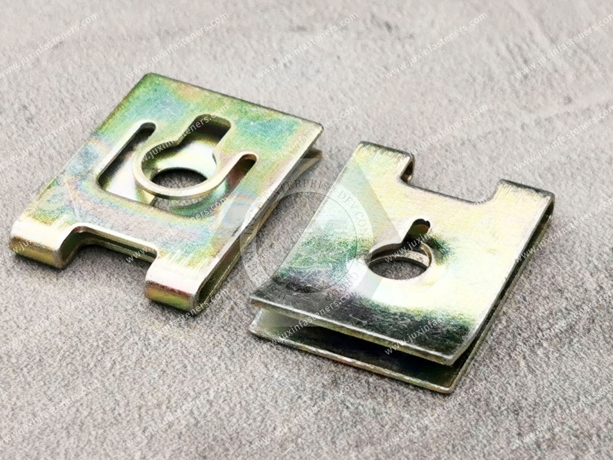
Previous: No-Slip Clip-On Barrel Nuts
Next: Clip-On Nuts Guide
 MORE NEWS

Sep. 27, 2026

Sep. 27, 2026

Sep. 27, 2026
Contact Us
Tel.:
+86 020 8621 0320
+86 020 3121 6067
E-mail:
Technical Support:
Navigation
SEND INQUIREY