
Call Us
+86 136 6007 9809
Call Us
+86 136 6007 9809

Oct. 25, 2023
Clip-on nuts are threaded fastening components designed to create a nut location on sheet-metal edges, panels, brackets,
housings, and similar structures without requiring a conventional loose nut behind the assembly.
Depending on the design and market terminology, related products may be described as U-nuts, clip nuts, spring nuts, threaded clip nuts, or sheet metal clip nuts.
These names can overlap, but the geometry and installation method are not necessarily identical.
For engineering and sourcing purposes, the actual part configuration should therefore be defined by drawing, dimensions, mating screw, panel interface, material, finish,
and application requirements rather than by product name alone.
For OEM and industrial assemblies, successful clip-on nut selection depends on more than thread size. Panel thickness, grip geometry, clip reach,
hole position, thread alignment, coating buildup, installation direction, service environment, and tolerance stack-up can all affect assembly performance.
This guide explains how engineers and procurement teams can evaluate these variables when specifying, replacing, or sourcing clip-on nuts.
A clip-on nut combines a spring-style clip body with a threaded feature to provide a removable threaded attachment point on a panel or structural edge.
The clip is normally pushed or slid over the edge of the mating panel. Its geometry provides retention before the screw is installed, while the threaded portion receives the mating screw during final assembly.
This can eliminate the need to hold a separate loose nut behind the panel and can simplify assembly where rear access is inconvenient.
Typical applications include:
Sheet-metal panels
Equipment housings
Automotive body and interior assemblies
Electrical enclosures
Mounting brackets
HVAC equipment
Industrial machinery covers
Commercial equipment
Appliance structures
Power and control equipment
The exact suitability depends on the clip geometry, panel design, material, finish, screw interface, loading condition, and service environment.
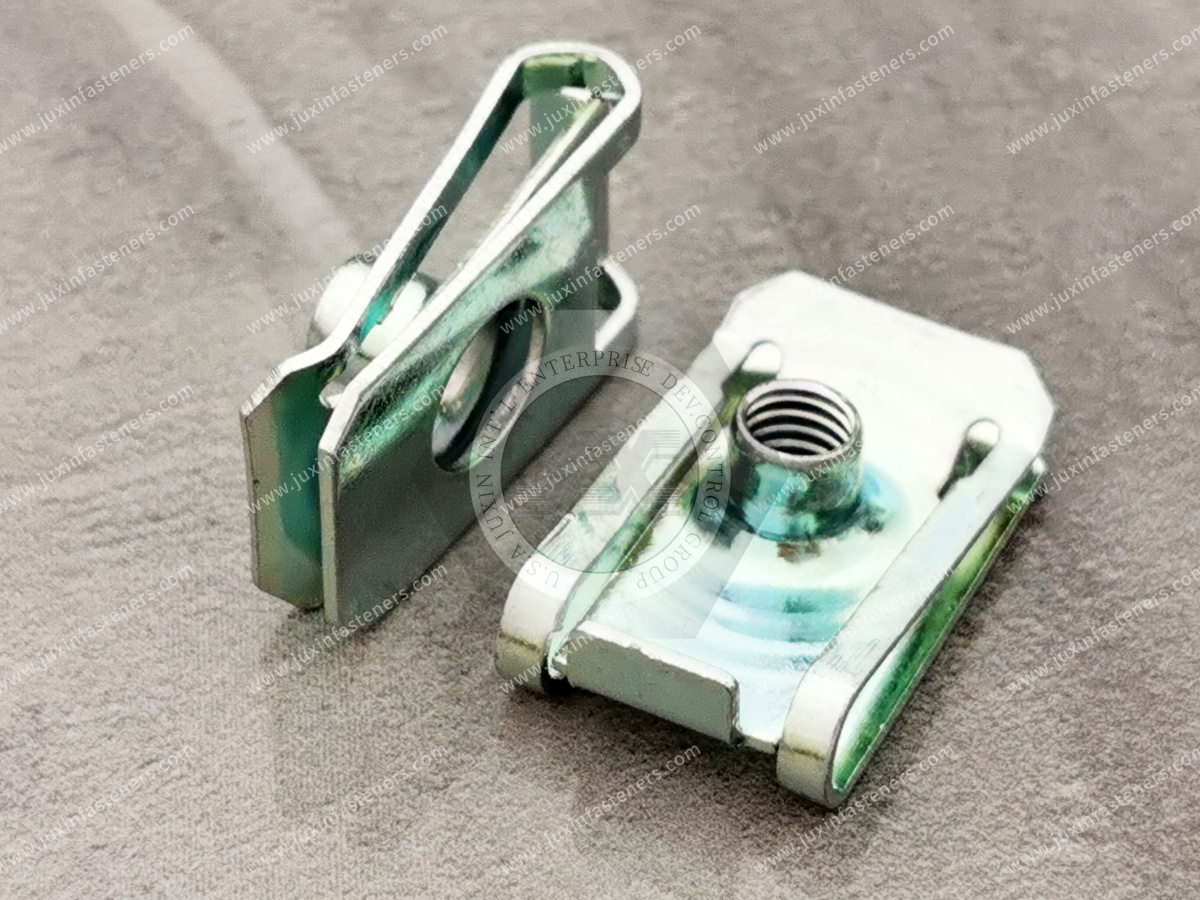
These terms are often used interchangeably in commercial searches, but engineers should not assume that every product sold under these names is geometrically equivalent.
A U-nut commonly has a U-shaped body that clips over the edge of a panel.
A clip nut is a broader commercial term for a nut retained to a panel by a clip or spring feature.
A spring nut can describe several types of spring-based fastening components and therefore requires additional dimensional definition.
A threaded clip nut more specifically indicates that the clip incorporates a machine-screw thread or threaded nut feature.
For replacement and second-source projects, terminology alone is insufficient.
Two parts described as the same type of U-nut may have the same thread but different panel engagement, reach, installation force, hole alignment, or overall envelope.
The drawing and actual assembly interface should control the sourcing decision.
A clip-on nut performs two related functions.
First, the spring geometry retains the component on the panel before final screw installation.
Second, the threaded feature provides the mating interface for the screw.
This distinction is important.
The spring portion should not automatically be treated as a universal thread-locking mechanism.
The final joint behavior depends on the complete assembly, including screw engagement, joint clamp load, mating surfaces,
material properties, geometry, vibration environment, and installation conditions.
Where vibration resistance is a critical design requirement,
the complete joint should be validated under the actual service conditions rather than assuming that the clip geometry alone will prevent loosening.
One of the first dimensions engineers should define is the thickness of the panel receiving the clip.
The clip opening and spring geometry must be compatible with the panel.
If the panel is too thick for the selected geometry, several problems may occur:
Excessive installation force
Permanent deformation of the clip
Damage to the panel finish
Incorrect seating
Poor alignment between the nut and panel hole
If the panel is too thin relative to the intended grip geometry, the clip may not be retained as intended before screw installation.
For this reason, an RFQ for a clip-on nut should ideally identify the actual panel thickness or thickness range rather than only specifying the thread size.
For clip-style fasteners, the relationship between the clip and panel should be treated as an interface specification.
Important factors can include:
Nominal panel thickness
Panel thickness tolerance
Surface coating or paint
Multiple-layer panel construction
Local embossing or formed features
Burrs around the panel edge
Required installation force
Required pre-assembly retention
A clip validated on bare sheet may behave differently after paint, powder coating, plating, or another surface treatment changes the effective interface thickness.
Engineers should therefore evaluate the finished panel condition, not only the nominal raw sheet thickness.
Thread size receives significant attention during sourcing, but clip reach can be equally important.
Clip reach describes the relationship between the panel edge and the location of the threaded feature. It must correspond to the position of the mating hole.
If the reach is incorrect, the thread center may not align with the screw path even when the thread size itself is correct.
For an edge-mounted clip-on nut, engineers should define or verify:
Distance from panel edge to hole center
Hole diameter or opening geometry
Clip insertion direction
Thread center position
Available installation clearance
Nearby bends, flanges, ribs, or formed features
These dimensions become particularly important when qualifying an alternative supplier against an existing production part.
A clip-on nut must allow the mating screw to enter the threaded feature correctly through the assembled components.
Misalignment can result from:
Incorrect clip reach
Panel-hole position variation
Clip movement during assembly
Excessive tolerance stack-up
Deformation during installation
Incorrect clip orientation
Mismatch between the replacement part and existing panel geometry
Possible assembly symptoms include difficult screw starting, angled engagement, cross-threading, inconsistent assembly time, or damage to the mating thread.
When alignment problems occur, changing the screw alone may not solve the issue. The entire panel-hole-clip interface should be reviewed.
Surface finish is not only a corrosion-protection decision.
Coating on either the clip or mating panel can influence:
Effective grip condition
Installation force
Sliding behavior during installation
Dimensional fit
Surface damage during assembly
Corrosion compatibility
The appropriate finish depends on the material combination, service environment, customer specification, appearance requirements, and assembly process.
Where coating thickness materially affects fit, the finished dimensions and assembly should be validated rather than relying solely on uncoated nominal dimensions.
Material selection should reflect both the spring function of the clip and the environment of the final assembly.
Depending on the product design and customer requirements, clip-on nuts may use suitable spring steels, carbon steels, stainless steels, or other specified materials.
Material selection should consider:
Required elastic behavior
Formability
Thread requirements
Corrosion environment
Mating panel material
Mating screw material
Surface finish
Temperature exposure
Assembly and service conditions
Stainless steel should not automatically be selected solely because corrosion resistance is required.
Engineers should also evaluate spring characteristics, forming requirements, thread behavior, mating materials, and the actual environment.
Similarly, plated carbon or spring steel configurations should be specified according to the required corrosion protection and customer drawing rather than treated as universally interchangeable.
Many clip-on nut problems are interface problems rather than defects in a single component.
Understanding the failure mode can make supplier development and troubleshooting more efficient.
Possible factors include:
Panel thickness outside the intended range
Incorrect clip geometry
Insufficient retention for the assembly process
Panel edge geometry mismatch
Dimensional variation
Clip deformation
Surface condition affecting grip
The correct response is to review the clip-to-panel interface rather than simply increasing spring force without considering installation requirements.
Possible factors include:
Thread center misalignment
Incorrect clip reach
Panel-hole positional variation
Clip shifting after installation
Screw entering at an angle
Thread mismatch
Tolerance stack-up
A mating-panel drawing can be particularly useful when diagnosing this issue.
Cross-threading may be related to thread alignment, screw entry angle, assembly tooling, dimensional variation, or mating-component geometry.
For automated or high-volume assembly, screw presentation and positional repeatability should be considered together with the clip design.
Potential causes include:
Panel thickness greater than intended
Coating buildup
Clip opening too small for the finished panel
Material or spring geometry mismatch
Interference with a panel feature
High installation force should not automatically be considered evidence of better retention.
Permanent deformation can indicate that the clip is operating outside its intended geometry or material condition.
The panel thickness, installation path, clip geometry, material, and manufacturing consistency should be reviewed.
Corrosion performance depends on the complete material and environmental system.
Engineers should consider:
Clip material
Panel material
Screw material
Surface treatments
Moisture exposure
Chemical exposure
Dissimilar-metal interactions where relevant
Customer corrosion requirements
Finish selection should therefore be application-specific.
Clip-on nuts and cage nuts can both provide threaded attachment points, but they solve different interface problems.
A clip-on nut is typically installed over an accessible panel edge and can be attractive where rapid edge installation and compact packaging are required.
A cage nut normally uses a captive nut retained within a cage and is commonly associated with panel openings designed for that fastening system.
Some cage-nut designs provide positional movement that can help accommodate assembly alignment.
An engineer should consider:
Panel access
Hole geometry
Required positional adjustment
Installation process
Serviceability
Load direction
Packaging space
The two technologies should not be treated as direct substitutes without reviewing the assembly.
Self-clinching fasteners are installed into properly prepared sheet material by controlled pressing, creating a mechanically retained fastener in the panel.
Clip-on nuts instead attach through clip geometry and generally do not require the same type of press installation.
A clip-on solution may be useful where edge access, rapid assembly, removability, or avoidance of a dedicated clinching operation is important.
A self-clinching solution may be considered where a permanently retained threaded feature integrated into a suitable panel is desired.
Selection depends on panel material, thickness, access, installation equipment, retention requirements, load conditions, and service strategy.
Rivet nuts, also known as blind threaded inserts, create a threaded attachment point by deforming the insert in a prepared hole.
They can be particularly useful where installation is performed from one side of the workpiece.
Clip-on nuts generally require access to a suitable panel edge or compatible mounting feature.
Therefore, an engineer choosing between these technologies should first ask:
Is an accessible panel edge available, or must the threaded attachment be installed through a hole from one side?
That interface question can quickly narrow the appropriate fastening technology.
Weld nuts are permanently attached through a welding process and are fundamentally different from clip-on fastening systems.
Where welding is already integrated into the manufacturing process and a welded threaded attachment is appropriate, a weld nut may be considered.
Where welding should be avoided or a removable clip-based installation is preferred, a clip-on nut may offer a different assembly route.
The decision should consider manufacturing sequence, material compatibility, coating sequence, access, service requirements, and joint performance.
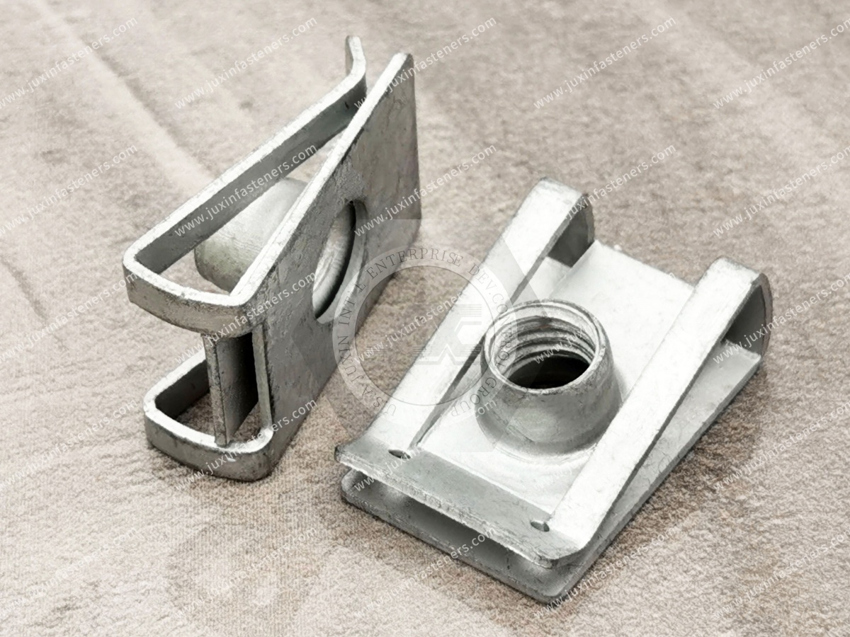
For a new clip-on nut application, engineers can use the following decision path.
Identify:
Panel material
Nominal thickness
Thickness tolerance
Surface finish
Edge geometry
Specify:
Thread size
Mating screw
Required engagement geometry
Screw installation direction
Provide:
Edge-to-hole-center distance
Hole or slot dimensions
Available clip envelope
Nearby bends and obstructions
Installation direction
Consider:
Indoor or outdoor service
Moisture
Chemicals
Temperature conditions
Corrosion requirements
Vibration or dynamic loading where relevant
Determine:
Manual or automated installation
Installation sequence
Required pre-assembly retention
Tool access
Service or replacement requirements
Where fit, alignment, retention, corrosion performance, or dynamic behavior is critical, validation should use representative production components and actual service conditions.
Automotive assemblies are a major application area for clip nuts, U-nuts, and related spring fasteners because vehicle structures contain many sheet-metal and formed-panel interfaces.
Potential applications include:
Body panels
Interior structures
Trim attachment
Brackets
Covers
Equipment mounting points
Selected underbody or enclosure interfaces where the design is suitable
Automotive selection should account for assembly sequence, panel coatings, vibration environment, corrosion exposure, service access, and mating-component tolerances.
A part used successfully in one vehicle assembly should not automatically be assumed suitable for another without reviewing the interface.
Clip-on nuts can also provide efficient threaded attachment points for:
Electrical cabinets
Equipment enclosures
Control panels
Power distribution equipment
Server and data center equipment structures
Cooling equipment
Industrial control systems
These applications often benefit from reducing loose hardware during assembly while maintaining service access.
Selection should consider enclosure material, panel thickness, grounding or electrical requirements where applicable, corrosion conditions, installation access, and equipment-specific specifications.
Machinery guards, covers, access panels, fan assemblies, equipment housings, and HVAC structures may use clip-style threaded fasteners where repeated production assembly or service access is required.
For these applications, engineers should evaluate whether the clip remains correctly located throughout manufacturing, transportation, service, and reassembly.
Repeated service requirements should be validated for the specific part and assembly rather than assuming unlimited reuse.
Second-source development requires more than finding a visually similar component.
For an existing production part, useful qualification information includes:
Existing drawing
Physical sample
Thread specification
Panel thickness
Panel drawing
Edge-to-hole-center dimension
Material
Finish
Mating screw
Installation method
Application environment
Annual demand
A physical sample is especially valuable when the legacy drawing does not fully define the spring geometry.
However, a sample alone may also be insufficient if its dimensions have changed through installation or previous use.
Where possible, the sample should be evaluated together with drawings and mating components.
Two clip-on nuts can look nearly identical on a desk but behave differently in production.
Small differences in:
Clip opening
Spring geometry
Reach
Thread position
Overall height
Material condition
Finish
Forming geometry
can change installation and alignment.
For this reason, second-source qualification should include the mating interface, not just dimensional comparison of the isolated fastener.
Where practical, trial assembly using representative panels and screws can help identify fit or alignment issues before production sourcing.
A drawing-controlled clip-on nut may need to define, as applicable:
Thread specification
Overall dimensions
Clip width
Clip opening
Thread center location
Reach
Material
Finish
Critical formed geometry
Dimensional tolerances
Mating panel requirements
Customer-specific inspection requirements
The exact drawing content depends on the design.
For custom components, identifying the dimensions that control the assembly interface is more useful than adding unnecessary dimensions that do not affect function.
Standard catalog components can satisfy many applications, but custom clip-on nuts may be required when an OEM has a specific panel geometry, packaging constraint,
material requirement, finish, thread location, or legacy assembly interface.
JUXIN FASTENERS supports sourcing and development of standard and custom industrial fasteners, including clip nuts, U-nuts, spring nuts, custom stamped components, and drawing-controlled parts.
Projects can begin from:
Customer drawings
Existing samples
Mating-component information
Application requirements
Existing parts requiring an alternative source
The development path should be based on the actual component and project requirements.
Please provide, where available:
Part drawing
Physical sample
Thread specification
Material
Finish
Panel thickness
Mating panel drawing or key dimensions
Mating screw information
Annual or order volume
Please provide:
Application
Panel material
Panel thickness
Edge-to-hole-center distance
Hole geometry
Required thread
Mating screw
Installation direction
Available packaging space
Service environment
Expected production volume
Providing the existing fastener + drawing + representative panel or interface dimensions + mating screw gives the supplier a stronger basis for
evaluating equivalence than relying on a product name or photograph alone.
Depending on the assembly architecture, engineers and sourcing teams may also evaluate:
Spring Nuts and U-Nuts
Cage Nuts
Self-Clinching Fasteners
Rivet Nuts
Weld Nuts
Custom Fasteners
Custom Stamped Components
Automotive Fasteners
Each technology creates a threaded attachment in a different way. Selection should begin with the panel geometry, access conditions,
manufacturing process, load requirements, service environment, and assembly strategy.
A clip-on nut is a small component, but its performance depends on the geometry around it.
For engineers, the critical questions are often not simply:
“What thread do I need?”
but:
“What panel thickness must the clip fit?”
“Where must the thread center sit relative to the panel edge?”
“Will coating buildup affect installation?”
“Can the screw enter without misalignment?”
“How will the clip behave in the actual assembly process?”
For procurement and supplier-development teams, these same questions help distinguish a visually similar replacement from a component that is properly matched to the production interface.
JUXIN FASTENERS supports standard, custom, OEM, drawing-controlled, sample-matching, and second-source fastener projects for global industrial customers.
For clip-on nut sourcing or custom development, send us your drawing, sample, mating-panel information, required thread, material and finish requirements, application details, and expected volume.
Email: info@juxinfasteners.com
Website: www.juxinfasteners.com
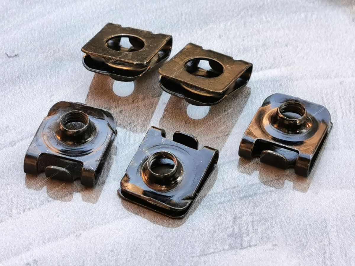
 MORE NEWS

Sep. 27, 2026

Sep. 27, 2026

Sep. 27, 2026
Contact Us
Tel.:
+86 020 8621 0320
+86 020 3121 6067
E-mail:
Technical Support:
Navigation
SEND INQUIREY