
Call Us
+86 136 6007 9809
Call Us
+86 136 6007 9809

Sep. 27, 2026
Nylon P-clips and plastic cable clamps are widely used to secure wire harnesses, electrical cables,
flexible tubing, small hoses, and other routed components to panels, frames, enclosures, and equipment structures.
Unlike a conventional cable tie, which primarily bundles multiple cables together, a screw-mount P-clip creates a defined mechanical attachment point between the routed bundle and the supporting structure.
The loop surrounds the cable or tube while the mounting foot is secured to the assembly with a screw, bolt, stud, or other specified mounting interface.
This apparently simple component can have a significant influence on harness movement, cable-jacket wear, vibration behavior, routing consistency, assembly efficiency, and long-term serviceability.
For engineers, selecting a plastic cable clamp therefore involves more than matching a nominal cable diameter.
Bundle compressibility, mounting-hole geometry, clamp closure, polymer behavior, temperature, moisture, vibration, chemical exposure, installation torque, and cable-jacket sensitivity may all affect performance.
For procurement and supplier-development teams, a visually similar P-clip should not automatically be treated as an interchangeable replacement.
Dimensional comparison, resin requirements, molding geometry, installation conditions, physical samples, and assembly validation should be considered before approving a second source.
Juxin Fasteners supplies standard and custom plastic fastening components for industrial OEM applications and supports projects using existing part numbers,
physical samples, dimensional requirements, 2D drawings, 3D CAD data, and application information.
A nylon P-clip, also called a plastic P-clip, nylon cable clamp, screw-mount cable clamp, cable retaining clamp, or wire harness clamp, normally consists of a molded loop and an integrated mounting section.
When viewed from the side, the installed component often resembles the letter “P,” which is the origin of the common industry name.
The loop retains the cable, wire harness, hose, or tube, while the mounting section provides a mechanical connection to the chassis, enclosure, bracket, panel, or machine structure.
Typical applications include:
wire harness routing
electrical cable retention
control wiring
sensor cable management
automotive harness attachment
EV electrical assemblies
battery and power-system cable routing
industrial automation equipment
machinery wiring
electrical cabinets and enclosures
telecommunications equipment
renewable-energy equipment
HVAC systems
flexible tubing retention
The suitability of a specific clamp depends on the actual assembly conditions rather than the product name alone.
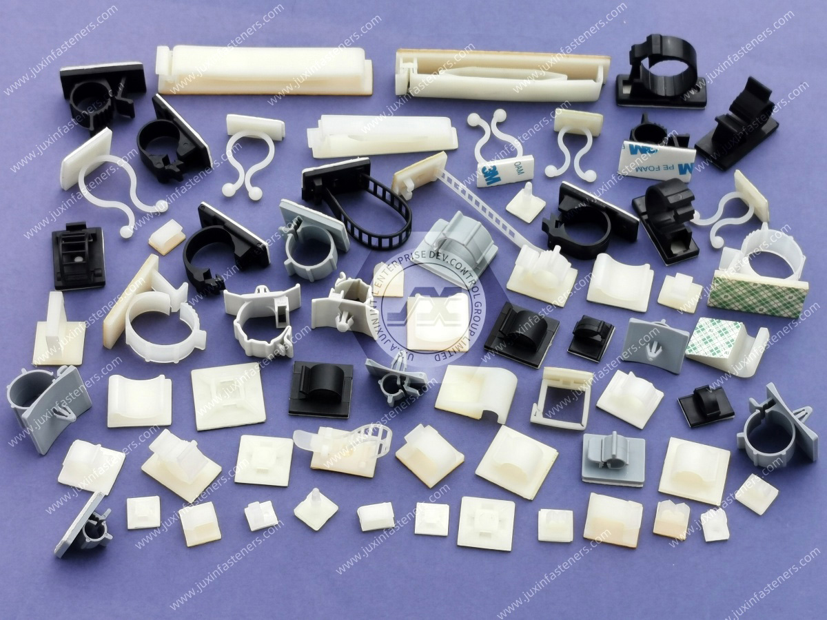
Cable-management products solve different mechanical problems.
A cable tie primarily consolidates a bundle. A cable tie mount provides an anchoring location for a separate tie.
A wire saddle may support or guide cables without completely enclosing them. A snap-in cable clip may attach directly to a panel hole without requiring a separate screw.
A P-clip combines bundle enclosure with a defined screw-mounted attachment point.
This makes P-clips particularly useful where engineers need controlled routing and positive attachment to a structure.
However, a P-clip is not automatically preferable to other cable-management methods. Selection should depend on:
required retention
bundle movement
serviceability
installation access
available mounting features
cable sensitivity
vibration environment
assembly sequence
expected removal requirements
packaging space
The correct decision is based on the complete routing system rather than one component in isolation.
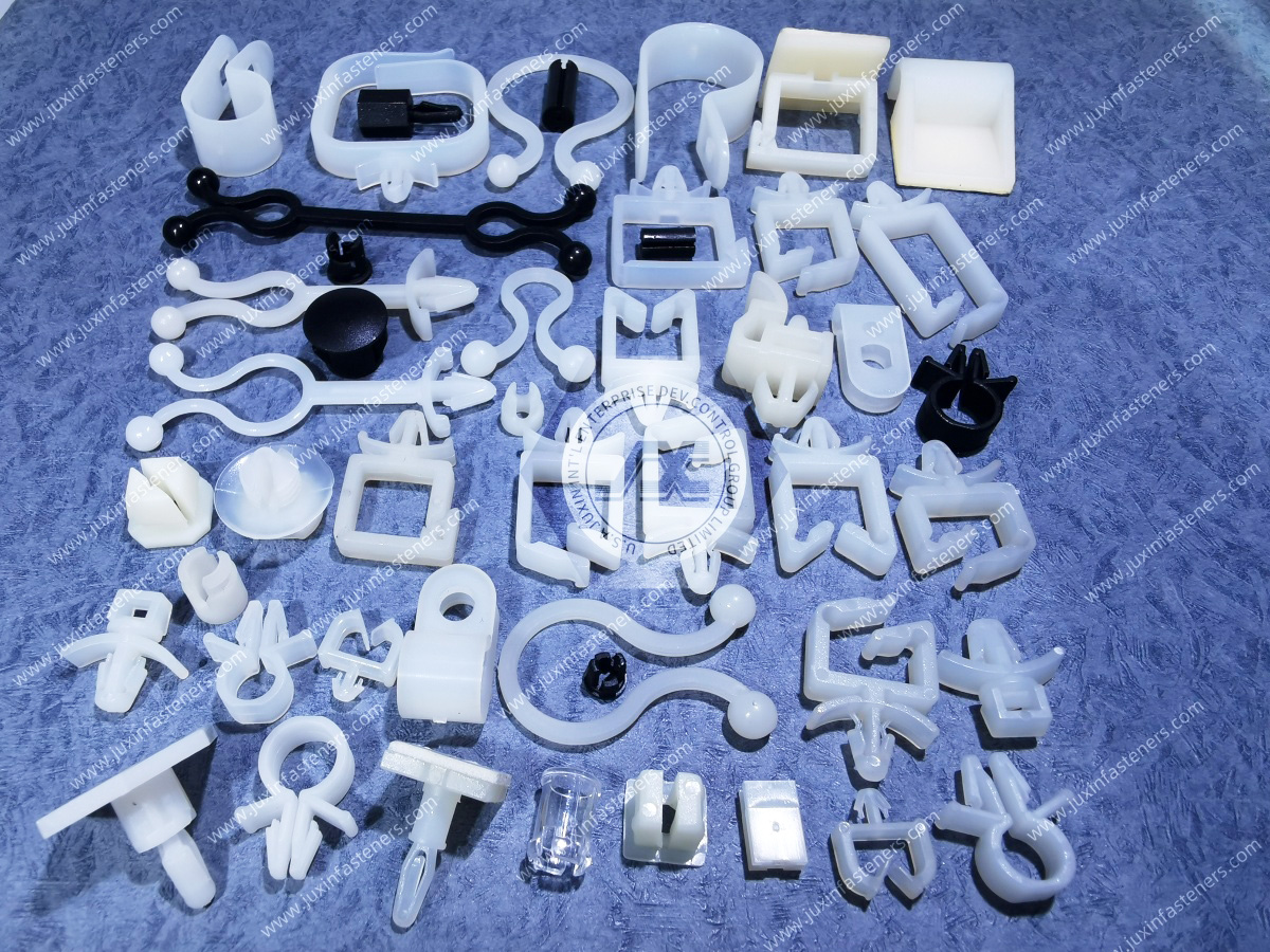
Plastic cable clamps are available in multiple geometries because different assemblies require different combinations of bundle retention, mounting access, clearance, and installation behavior.
Standard P-clips typically use a looped body with two ends brought toward the mounting point.
When the mounting fastener is installed, the geometry retains the enclosed cable or tubing against the supporting structure.
These components are commonly used where a compact, economical, screw-mounted retention point is required.
Some molded cable clamps use adjustable or multi-position locking features.
These can be useful when an application must accommodate a limited range of bundle sizes or when the assembly sequence makes a fixed closed-loop geometry less practical.
The actual adjustment range and retention behavior should be verified from the specific component design rather than assumed from appearance.
Standoff designs create separation between the retained cable and the mounting surface.
This can be valuable when routing requires clearance from:
sheet-metal edges
adjacent components
moving mechanisms
potential abrasion points
surfaces with unsuitable thermal conditions
other harnesses or tubing
The standoff dimension should be evaluated together with the cable bend path and surrounding assembly envelope.
Some applications use wider or structurally reinforced clamp geometries to distribute contact over a larger portion of the cable or tubing.
This may be useful for larger or more jacket-sensitive bundles, but band width alone does not determine suitability.
The cable construction, contact pressure, clamp geometry, vibration, mounting conditions, and required retention should be evaluated together.
A common sourcing mistake is specifying only the nominal diameter.
Two bundles with the same measured outside diameter can behave very differently inside a P-clip.
For example, the retained item may be:
a single electrical cable
a multi-wire harness
corrugated conduit
braided sleeving
flexible tubing
a rubber hose
a wrapped automotive harness
a high-voltage cable
a sensor cable
a pneumatic tube
Each has different compressibility, surface friction, jacket sensitivity, stiffness, and tolerance behavior.
This leads to an important engineering principle:
Bundle outside diameter is necessary information, but it is not sufficient by itself to select a cable clamp.
The engineer should also consider what the bundle is made from and how much compression or movement is acceptable.
The nominal loop diameter of a P-clip should not be interpreted as a universal guarantee of fit.
Actual installed behavior depends on:
free-state clamp geometry
bundle outside diameter
bundle tolerance
bundle compressibility
cable jacket construction
clamp wall thickness
polymer stiffness
mounting-foot geometry
fastener installation
environmental conditioning
An undersized clamp can create excessive local compression, deform cable jackets, increase assembly force, or prevent the mounting features from seating correctly.
An oversized clamp may permit cable movement.
Under repeated vibration, relative motion between the bundle and clamp can contribute to abrasion or chafing.
For this reason, engineers replacing an existing clamp should evaluate the installed condition rather than simply comparing catalog diameter descriptions.
Polymer selection is one of the most important differences between cable clamps that may appear geometrically similar.
PA66 is commonly used for many molded cable-management components because appropriate grades can provide a useful balance of stiffness, toughness, moldability, and fatigue behavior.
However, “nylon” should not be treated as one universal material specification.
Performance can differ significantly according to:
polymer family
resin grade
additives
reinforcement
conditioning
temperature
moisture
UV exposure
chemical environment
molding conditions
If the existing component specifies a particular material or resin grade, a replacement should be reviewed against that requirement rather than approved simply because both products are described as nylon P-clips.
Where cable clamps operate near elevated-temperature equipment, a suitable heat-stabilized polymer grade may be considered.
Potential applications can include areas near:
power electronics
industrial drives
inverter assemblies
machinery heat sources
automotive underhood systems
Temperature capability must be based on the actual resin grade and application conditions. A generic “nylon” designation does not establish a universal operating-temperature rating.
Outdoor applications may require a polymer formulation designed for UV exposure.
Examples can include:
renewable-energy equipment
outdoor electrical equipment
agricultural machinery
transportation equipment
telecommunications installations
Standard nylon should not automatically be assumed to provide the required long-term outdoor weathering performance.
The specified resin grade and exposure conditions should be reviewed.
Polyamides such as PA6 and PA66 are hygroscopic and can absorb moisture from their environment.
This matters because moisture conditioning can influence mechanical and dimensional behavior.
Depending on resin grade and environmental conditions, moisture may affect:
dimensions
stiffness
toughness
strength
flexibility
insertion or closing behavior
retention
contact pressure
creep
stress relaxation
This is especially relevant when a clamp is evaluated immediately after molding or in a dry laboratory condition but will later operate in a humid field environment.
Dry-as-molded properties should therefore not automatically be treated as representative of long-term installed behavior.
For critical applications, engineers should consider the actual conditioning and environmental state expected during assembly and service.
Plastic cable clamps can remain mechanically deflected for long periods after installation.
Polymers are viscoelastic materials, so sustained strain can result in stress relaxation, while sustained load can produce creep.
This means that initial clamping behavior is not necessarily identical to long-term clamping behavior.
The rate and significance depend on factors including:
resin grade
temperature
moisture
clamp geometry
amount of deformation
bundle stiffness
installation condition
service duration
This becomes particularly important when the retained bundle is heavy, rigid, vibration-sensitive, or expected to remain in service for long periods.
The design objective should not simply be maximum initial clamp force. It should be stable and appropriate retention throughout the intended service conditions.
The mounting interface is as important as the cable loop.
P-clips may be used with metric or inch-series screws, bolts, studs, or other attachment systems depending on the assembly.
Common industrial projects may use mounting hardware associated with metric sizes such as M4 or M5,
or Unified inch-series fasteners, but there is no universal mounting-hole size for a plastic cable clamp.
The following should be evaluated:
clamp mounting-hole diameter
mounting-hole tolerance
screw or bolt diameter
head geometry
washer arrangement where applicable
tapped-hole or nut interface
mounting-surface thickness
available tool access
clamp-foot thickness
surrounding clearance
installation torque
A replacement clamp with the correct loop diameter but the wrong mounting-hole geometry may still be unsuitable.
It is tempting to specify one universal tightening torque for a given P-clip mounting screw.
That approach can be misleading.
The appropriate installation condition depends on the complete joint, including:
screw size
screw material and strength
mating thread
mounting surface
clamp-foot geometry
polymer grade
washer arrangement
required retention
allowable clamp deformation
Excessive tightening may deform or damage the polymer mounting feature.
Insufficient tightening may permit movement at the mounting interface.
Installation requirements should therefore be established according to the actual joint design and validated assembly conditions.
A cable clamp can meet nominal dimensions and still create reliability problems if the cable-contact surface is poorly controlled.
Engineers should inspect areas that contact the cable for:
sharp edges
molding flash
gate vestiges
rough surfaces
abrupt geometry transitions
localized pressure points
These features matter because repeated relative motion under vibration can gradually damage cable insulation or protective sleeving.
For wire-harness applications, cable protection should therefore be treated as a functional requirement, not merely a cosmetic molding issue.
In many transportation and machinery applications, the most important function of the clamp is not simply preventing the cable from falling out.
It is controlling relative movement.
A useful engineering sequence is:
Vibration source → harness movement → clamp/bundle relative motion → jacket friction → abrasion → potential insulation damage
This explains why clamp spacing, bundle fit, routing geometry, support location, and surrounding structure can be as important as the clamp material itself.
A P-clip cannot compensate for a poorly designed harness-routing system.
Engineers should evaluate the complete support arrangement, particularly around:
connectors
cable bends
branch points
heavy harness sections
moving assemblies
vibration sources
sharp panel edges
Plastic clamps, copper conductors, polymer cable jackets, aluminum structures, and steel chassis components do not expand identically with temperature.
Thermal cycling can therefore alter local stresses and cable position.
This becomes increasingly important in applications with:
long cable runs
large temperature changes
constrained routing
rigid cable constructions
multiple fixed support points
Engineers should avoid using cable clamps to create unintended axial constraint where the harness requires accommodation for thermal movement.
Many engineering polymers are electrically insulating, which can make plastic cable clamps useful where designers want to avoid direct metal-to-cable contact.
However, the presence of a polymer clamp does not by itself establish electrical-system safety.
A plastic P-clip should not automatically be interpreted as satisfying:
creepage requirements
clearance requirements
dielectric withstand requirements
high-voltage isolation requirements
system-level electrical certification
Those requirements depend on the complete electrical design, geometry, material grade, voltage environment, contamination conditions, and applicable standards.
Plastic cable clamps can contribute to a mechanical and electrical isolation strategy, but they do not replace system-level electrical engineering.
Industrial cable clamps may encounter:
lubricants
greases
hydraulic fluids
coolants
cleaning chemicals
fuels
process chemicals
salt or moisture
other application-specific fluids
No generic plastic material should be described as chemically resistant to all of these environments.
Compatibility depends on the specific polymer grade, chemical, concentration, temperature, exposure duration, stress state, and environmental combination.
For chemically demanding applications, the actual exposure should be disclosed during material selection.
A practical engineering selection process can follow this sequence:
Application → Environment → Bundle → Material → Mounting Interface → Clamp Geometry → Installation → Validation
Determine what must be retained and why the clamp is required.
Identify temperature, moisture, UV, vibration, and chemical exposure.
Define outside diameter, tolerance, construction, compressibility, weight, and jacket sensitivity.
Select a polymer grade according to the actual mechanical and environmental requirements.
Confirm the mounting hole, screw or stud, supporting structure, and available installation space.
Review loop size, band width, mounting-foot geometry, standoff requirements, and surrounding clearance.
Consider assembly access, fastener tightening, cable insertion sequence, and potential polymer deformation.
Evaluate physical samples in the intended assembly before production qualification where application risk justifies validation.
This process is more reliable than selecting a cable clamp from bundle diameter alone.
Failure analysis can also help engineers select replacement components.
Possible causes include:
excessive loop size
incorrect bundle diameter assumption
bundle compression after installation
polymer relaxation
inadequate support layout
Possible contributors include:
relative motion
oversized clamp
rough internal surface
mold flash
unsuitable support location
excessive vibration
Possible contributors include:
excessive installation deformation
unsuitable polymer condition
excessive fastener tightening
environmental degradation
stress concentration
vibration fatigue
Possible contributors include:
creep
stress relaxation
elevated temperature
moisture conditioning
unsuitable geometry
changing bundle dimensions
Possible causes include:
incorrect hole location
dimensional mismatch
incompatible foot geometry
tolerance stack-up
attempting to substitute a visually similar part
These examples demonstrate why dimensional and application review is necessary during replacement or second-source projects.
Nylon cable clamps can be used for wire harnesses, sensor cables, control wiring, low-voltage routing, and other cable-management applications where the selected material and geometry meet the assembly requirements.
EV projects may require additional attention to temperature, cable diameter, electrical architecture, vibration, and routing around battery and power-electronics systems.
Automation systems use cable-management hardware for control wiring, sensors, actuators, machine frames, cabinets, and auxiliary equipment.
Where motion is present, fixed P-clips should be distinguished from cable-management components specifically designed for continuous dynamic flexing.
Plastic cable clamps may support organized routing inside switchgear, power-distribution equipment, power electronics, control cabinets, UPS systems, and related assemblies.
Electrical isolation and flame-performance requirements, where applicable, must be verified against the specified material and complete system design.
Solar, wind, battery energy storage, inverter, and related power systems can require structured cable routing.
Outdoor projects may introduce additional requirements for UV exposure, moisture, temperature cycling, and environmental durability.
Cable clamps can support internal equipment wiring, power cables, control wiring, and auxiliary harness routing.
Selection should consider serviceability, cable density, airflow constraints, and the equipment's electrical and thermal architecture.
HVAC units, pumps, industrial machinery, and process equipment may use plastic clamps to retain electrical cables, sensor wiring, and selected tubing.
Exposure to vibration, heat, oils, cleaning agents, and service operations should be considered.
Plastic cable-management hardware can be used in equipment where compact routing and non-metallic retention are useful.
Material, cleaning-agent exposure, regulatory requirements, and application-specific performance must be evaluated according to the actual equipment design.
This is particularly important for procurement teams seeking a second source.
Two black or natural-colored nylon P-clips may look nearly identical in a catalog photograph but differ in:
loop inside geometry
mounting-hole diameter
mounting-hole position
band width
wall thickness
foot thickness
edge radius
molding details
polymer family
resin grade
conditioning
UV stabilization
heat stabilization
flame-performance classification
dimensional tolerances
A purchasing decision based only on color, nominal diameter, and appearance can therefore create qualification problems.
The correct objective is not to find a part that “looks the same.”
The objective is to determine whether the candidate component is functionally suitable for the actual assembly.
For OEMs and Tier-level manufacturers, cable clamps are often sourced as established production components.
A second-source project can follow this pathway:
Existing Manufacturer / Part Number → Dimensional Review → Material Review → Candidate Cross-Reference → Physical Sample → Assembly Validation → Supplier Qualification → Production RFQ
Provide the current manufacturer and part number where available.
This helps identify the intended product family and specification baseline.
Critical dimensions may include:
loop diameter
band width
mounting-hole diameter
hole position
foot geometry
overall dimensions
wall thickness
relevant tolerances
Confirm whether the existing product specifies:
PA6
PA66
another engineering polymer
heat-stabilized grade
UV-stabilized grade
flame-rated grade
another application-specific resin
Equivalent appearance does not establish equivalent material performance.
A candidate replacement can then be evaluated against the dimensional, material, and application requirements.
A cross-reference should be treated as an engineering candidate until validated rather than automatically described as a fully interchangeable equivalent.
Physical samples allow engineering teams to verify:
bundle fit
mounting alignment
installation behavior
surrounding clearance
cable compression
service access
assembly compatibility
Additional application-specific testing may be required according to the customer's qualification process.
Standard P-clips do not cover every industrial assembly.
Custom development may be considered when a project requires:
non-standard loop geometry
special bundle diameter
unusual mounting-hole configuration
integrated standoff
restricted installation envelope
special material requirement
custom color
customer-specific dimensional interface
Juxin Fasteners can review drawing-based plastic fastening projects using customer-provided dimensional requirements, physical samples, 2D drawings, or 3D CAD information.
The development path can follow:
Application Requirement → Geometry and Material Review → Candidate Design → Sample / Prototype Evaluation → Assembly Validation → Qualification → Production RFQ
For fully custom drawing-based components:
2D/3D Drawing → Engineering Review → Material and Manufacturability Review → Sample / Prototype → Customer Qualification → Production
Industrial procurement involves more than obtaining a unit price.
Supplier-development and sourcing teams may also need to define:
material specification
drawing revision
dimensional requirements
color
required documentation
environmental compliance requirements
lot identification or traceability requirements
packaging
order quantity
estimated annual volume
sample requirements
Where RoHS, REACH, material documentation, or other declarations are required,
those requirements should be identified during the RFQ process and confirmed for the specific product and material rather than assumed.
To evaluate a standard, replacement, second-source, or custom cable clamp project efficiently, provide as much of the following information as available:
existing manufacturer
existing part number
physical sample
2D drawing
3D CAD model
cable or bundle outside diameter
bundle diameter tolerance
cable, harness, hose, or tubing type
bundle compressibility where relevant
mounting-hole diameter
mounting screw or stud size
mounting-surface information
required loop geometry
band width where controlled
standoff requirement
material or resin grade
color
operating temperature requirements
moisture exposure
UV exposure
chemical or fluid exposure
vibration conditions
cable-jacket sensitivity
flame-performance requirement, if applicable
electrical requirements, if applicable
required documentation
sample quantity
production order quantity
estimated annual volume
packaging requirements
Providing the existing component together with its application information is particularly valuable for second-source projects.
For a new application, the sourcing process can follow:
Application Requirement → Bundle and Environment Review → Material and Geometry Selection → Candidate Clamp → Sample → Assembly Validation → Production RFQ
For an existing production component:
Existing Part Number or Sample → Dimensional and Material Review → Candidate Cross-Reference → Sample → Assembly Validation → Second-Source Qualification → Production RFQ
For a custom component:
2D/3D Drawing → Engineering Review → Material and Manufacturability Review → Sample / Prototype → Qualification → Production
This structured process helps engineering, procurement, supplier quality, and supply-chain teams evaluate cable clamps based on actual functional requirements rather than catalog appearance alone.
Juxin Fasteners supplies plastic and nylon fastening components for industrial OEM and manufacturing applications, including cable-management hardware and related plastic fasteners.
Engineering and sourcing teams can submit an existing manufacturer part number, competitor part number, physical sample, dimensional specification,
2D drawing, 3D CAD model, material requirement, application information, and expected purchasing volume for evaluation.
For second-source projects, the objective is to establish a technically appropriate candidate for customer evaluation and qualification rather than assume interchangeability from appearance alone.
For new and custom projects, early communication about the assembly environment, bundle geometry, mounting interface,
material requirements, and expected production volume can reduce unnecessary sourcing iterations and support a more efficient path from engineering review to RFQ.
Email: info@juxinfasteners.com
Website: www.juxinfasteners.com
 MORE NEWS

Sep. 27, 2026

Sep. 27, 2026

Sep. 27, 2026
Contact Us
Tel.:
+86 020 8621 0320
+86 020 3121 6067
E-mail:
Technical Support:
Navigation
SEND INQUIREY