
Call Us
+86 136 6007 9809
Call Us
+86 136 6007 9809

Sep. 27, 2026
Nylon snap bushings and plastic panel hole protectors provide a controlled interface where electrical wires, cable bundles, flexible tubing, hoses,
or other routed components pass through holes in sheet-metal panels, electrical enclosures, equipment housings, brackets, and structural partitions.
Without suitable edge protection, a punched, stamped, drilled, laser-cut, or otherwise manufactured metal opening can expose the routed cable to burrs,
sharp edges, local contact pressure, and repeated rubbing. In vibrating equipment, even relatively small cable movement can create long-term chafing at an unprotected panel edge.
A snap bushing converts that raw panel opening into a smoother polymer-lined pass-through while its molded retaining features hold the component in the panel.
Although the component appears simple, correct selection requires more than matching a nominal hole diameter.
Engineers should evaluate the relationship between:
panel hole diameter and tolerance
panel thickness
bushing retention geometry
cable or bundle outside diameter
connector dimensions where relevant
cable movement
panel burr condition
installation direction
polymer grade
temperature and moisture
vibration
chemical exposure
service and replacement requirements
For procurement and supplier-development teams, visually similar snap bushings should not automatically be treated as interchangeable.
Two components intended for the same nominal panel hole can differ in panel-thickness capability, locking-finger geometry,
flange dimensions, internal clearance, resin grade, molding details, and installed retention.
Juxin Fasteners supplies standard and custom plastic fastening components for industrial OEM applications and supports snap-bushing projects using existing part numbers, physical samples,
dimensional requirements, 2D drawings, 3D CAD models, material specifications, and application information.
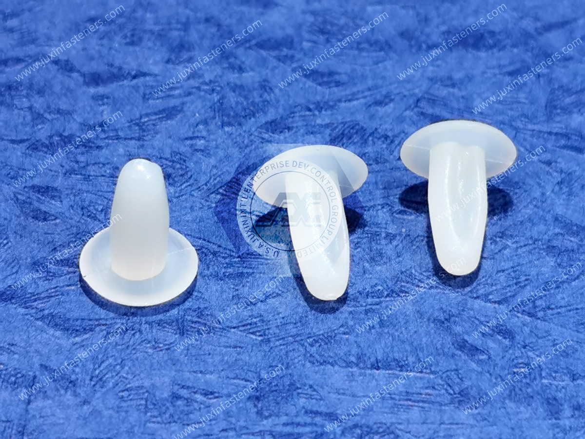
A nylon snap bushing is a molded panel-mounted component designed to fit into a prepared opening and create a protective passage through the panel.
Common industry and procurement terminology includes:
nylon snap bushing
plastic snap bushing
panel hole protector
plastic cable bushing
wire protection bushing
hole liner
snap-in bushing
insulating bushing
sheet metal hole bushing
panel bushing
cable pass-through bushing
The exact terminology varies by manufacturer and industry.
Most snap-in designs use a flange on the insertion side together with flexible molded retaining fingers, shoulders, or locking features that deflect during installation and engage the opposite side of the panel.
The flange controls the front-side seating condition while the retaining geometry resists removal or axial movement.
This makes the panel itself part of the fastening system.
A cable passing through a sheet-metal enclosure can experience several mechanical risks.
These include:
sharp panel edges
burrs
cable movement
vibration
cable jacket compression
repeated rubbing
assembly damage during cable pulling
contact with grounded metal structures
A snap bushing creates a polymer interface between the routed component and the panel edge.
However, the bushing should not be considered a substitute for correct cable routing, strain relief, environmental sealing, or system-level electrical protection.
Its primary role is normally panel-edge protection and cable pass-through management.
These product families are sometimes grouped together commercially, but they perform different functions.
Snap bushings primarily protect wires or cables as they pass through a panel opening.
They generally provide a relatively open internal passage and are not automatically designed to grip the cable.
Flexible grommets may provide edge protection while using a more compliant body or groove around the panel opening.
Their installation method and panel interface differ from rigid or semi-rigid snap bushings.
Strain relief bushings are designed to manage forces transferred from a cable into equipment.
Depending on design, they may grip or constrain the cable and help prevent external pulling or bending forces from being transferred directly to internal electrical connections.
A standard snap bushing should therefore not automatically be specified where cable strain relief is required.
This distinction is important for both engineers and purchasing teams because components can look similar in catalogs while serving different mechanical functions.
Snap bushings are available in multiple configurations to accommodate different assembly sequences and panel designs.
A standard round snap bushing typically uses a front flange and flexible retaining features around the body.
During insertion, the retaining features deflect inward.
After passing through the panel, they recover toward their molded position and engage the rear side of the panel.
The resulting installed retention depends on the interaction between:
Hole Diameter + Panel Thickness + Retaining Geometry + Polymer Condition
Changing any one of these variables can alter installation and retention behavior.
Split, slotted, or open-throat designs can be useful where a bushing must be installed around an existing wire, harness, or tube.
This can be particularly valuable when:
connectors are already installed
harnesses cannot easily be disconnected
tubing is already routed
field retrofit is required
assembly sequencing prevents installation before wiring
The exact closure and retention mechanism varies by design, so split bushings should be evaluated against the actual cable and panel geometry.
Low-profile snap bushings reduce projection from the panel surface where packaging space is restricted.
This can be useful inside compact:
control cabinets
electrical enclosures
telecommunications equipment
electronic assemblies
instrumentation
Reduced projection, however, should not be evaluated independently of flange strength, cable clearance, and retention requirements.
Plastic hole plugs and blanking plugs may use similar snap-fit retention principles but serve a different purpose: closing an unused panel opening.
A standard hole plug should not automatically be described as waterproof, dust-tight, airtight, or capable of meeting a particular ingress-protection rating.
Those performance requirements depend on the specific component geometry, panel interface, material, sealing features, installation condition, and validated system design.
One of the most important engineering concepts for snap bushings is that the sheet-metal cutout is not merely empty space.
It is a functional mating feature.
The bushing and panel work together as a snap-fit system.
The correct selection therefore requires evaluation of both parts of the interface.
Important panel variables include:
nominal hole diameter
hole tolerance
hole shape
panel thickness
panel-thickness tolerance
burr condition
edge condition
coating or finish
local panel flatness
installation direction
A bushing cannot be evaluated correctly without understanding the panel into which it will be installed.
The mounting hole diameter controls how the retaining features interact with the panel.
If the hole is too small, possible problems include:
excessive insertion force
incomplete installation
damaged locking fingers
bushing deformation
flange not seating against the panel
If the hole is too large, possible problems include:
radial looseness
axial play
reduced retention
vibration movement
rattling
inconsistent positioning
This is why selecting a snap bushing from a nominal hole description alone can be risky when replacing an established production component.
The actual panel drawing and tolerance should be reviewed where fit is critical.
Snap-fit retention geometry is normally designed around a particular panel-thickness condition or range.
If the panel is thicker than the intended interface, the locking features may not fully recover behind the panel.
Possible results include:
incomplete seating
reduced retention
excessive installation force
locking-feature deformation
If the panel is significantly thinner than the intended condition, excessive axial movement may occur depending on the design.
Therefore:
Same Hole Diameter ≠ Same Snap-Bushing Compatibility
Panel thickness must be evaluated at the same time as panel hole diameter.
This is a frequent second-source issue.
Two suppliers may describe products for the same nominal mounting hole, yet the parts can still differ in:
recommended panel thickness
retaining-finger geometry
flange diameter
flange thickness
body diameter
inside diameter
overall length
entry radius
polymer grade
stiffness
molding tolerance
One component may install correctly while another produces excessive insertion force, insufficient retention, or inadequate cable clearance.
For procurement teams, nominal hole diameter should therefore be treated as a starting point for cross-reference—not proof of interchangeability.
Many snap bushings use circular holes, but specialized plastic panel hardware can also be designed around other cutout geometries.
Where non-round panel openings are used, the following may become important:
rotational orientation
anti-rotation features
corner radii
cutout dimensions
insertion direction
tolerance stack
Custom panel hardware should therefore be reviewed against the actual cutout drawing rather than simplified to an equivalent circular diameter.
Panel manufacturing processes can influence snap-bushing installation.
Stamped, punched, drilled, or cut openings may have different edge conditions.
A pronounced burr can:
increase installation force
interfere with locking-feature movement
prevent full flange seating
damage the bushing
create inconsistent retention
remain exposed to the cable if the bushing does not fully cover the edge
Engineers should therefore consider:
hole-making process
burr height and direction
deburring requirements
coating thickness
panel edge condition
A snap bushing should not be used as justification for uncontrolled sheet-metal burrs.
Good panel preparation remains part of the assembly design.
Another common design error occurs when the engineer sizes the bushing only for the cable diameter.
If a cable or harness must be pulled through the installed bushing, the largest object that must pass through may actually be:
connector housing
terminal
splice
ferrule
sleeving
conduit fitting
branch point
This creates two different engineering questions:
What diameter must the bushing protect during service?
and
What maximum geometry must pass through the bushing during assembly?
If a connector cannot pass through the bushing ID, the assembly sequence may require:
installing the cable first
using a split bushing
terminating the connector after routing
selecting a different pass-through solution
This assembly-sequence analysis can prevent late-stage production problems.
The internal opening should accommodate the routed component without creating unacceptable compression or abrasion.
Engineers should consider:
maximum cable OD
cable OD tolerance
bundle shape
harness wrapping
conduit dimensions
connector passage requirements
cable movement
required service clearance
An excessively tight opening can pinch or abrade the cable.
An unnecessarily large opening may permit additional movement, although the significance depends on the routing and support system.
The objective is not simply to maximize clearance. It is to provide appropriate protection and assembly access for the actual cable system.
Material choice influences installation, retention, environmental behavior, and long-term durability.
PA66 is commonly used for many molded plastic bushings because suitable grades can provide a practical balance of stiffness, toughness, wear behavior, and moldability.
However, PA66 should not be treated as the universal material for every snap bushing.
Depending on the product and application, other polymers or application-specific resin formulations may be appropriate.
The actual material should be confirmed from the product specification.
Where bushings are used in elevated-temperature environments, a heat-stabilized resin may be considered.
Potential applications include:
power-distribution equipment
industrial drives
power electronics
switchgear
machinery enclosures
selected automotive electronics
The allowable operating environment depends on the specific resin grade, mechanical loading, conditioning, and required service life.
A generic nylon designation does not establish a universal temperature rating.
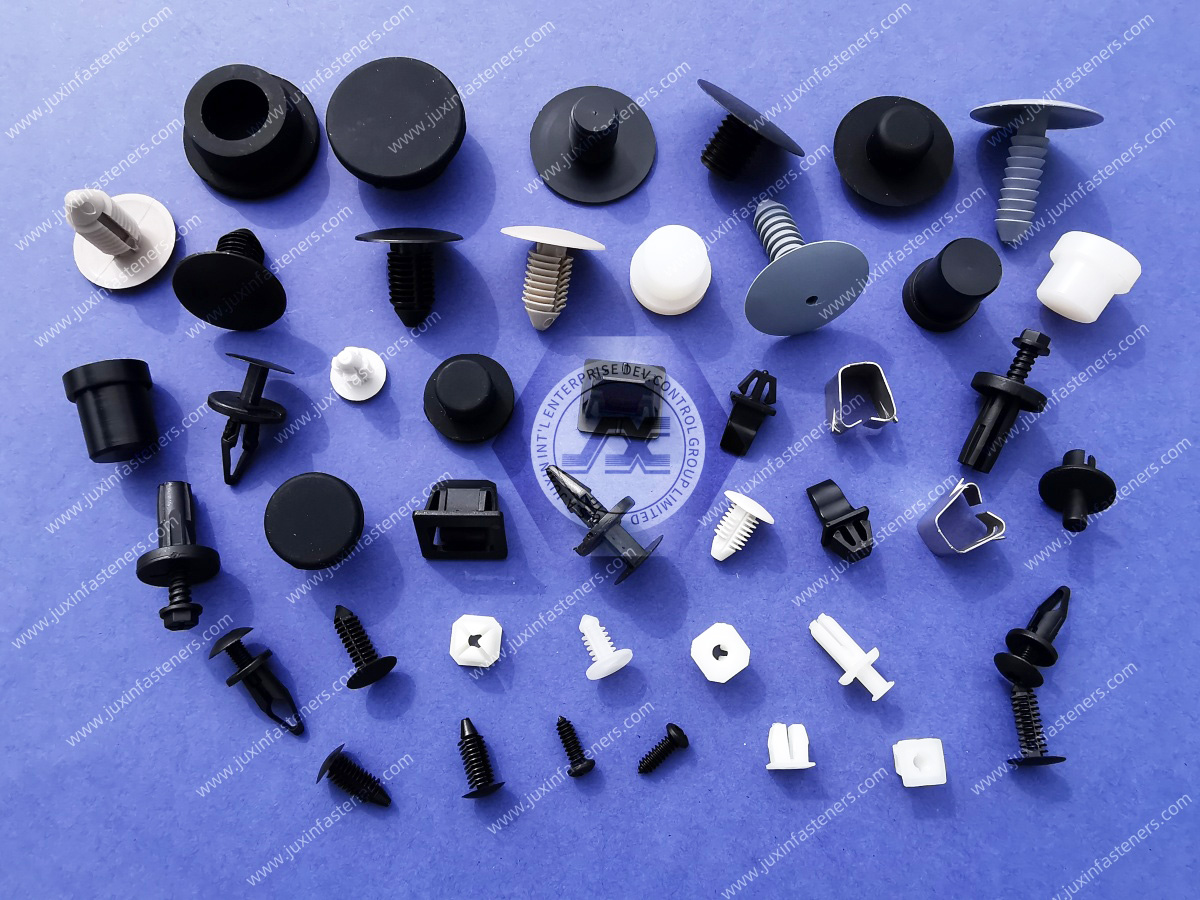
Polyamides such as PA6 and PA66 absorb moisture from their environment.
Moisture conditioning can affect:
dimensions
stiffness
toughness
strength
flexibility
insertion behavior
locking-finger response
retention behavior
creep
stress relaxation
Conditioned nylon may behave differently from dry-as-molded material, but this should not be simplified into a claim that moisture automatically improves the component.
The effect depends on the resin grade, geometry, conditioning state, environment, and functional requirement.
For snap-fit components, this is particularly relevant because locking fingers must deflect during installation and then provide appropriate installed retention.
A sample evaluated under one conditioning state may therefore behave differently after extended environmental exposure.
Snap-fit components can maintain elastic deformation after installation.
Because engineering polymers are viscoelastic, long-term retention can be influenced by creep and stress relaxation.
Relevant variables include:
polymer grade
initial deflection
panel thickness
locking geometry
temperature
moisture
service duration
This does not mean that nylon snap bushings inherently lose retention.
It means long-term behavior should be evaluated according to the specific component geometry, resin, and environment where retention is functionally important.
A snap bushing protects the cable from direct contact with a raw metal edge, but the complete routing system still controls cable movement.
A useful failure sequence is:
Equipment Vibration → Cable Movement → Relative Motion at Pass-Through → Repeated Surface Contact → Jacket Wear
Engineers should therefore evaluate not only the bushing but also:
cable support spacing
nearby cable clamps
strain relief
harness weight
bend geometry
connector location
movement amplitude
surrounding structures
Where substantial cable movement exists, additional harness support may be required.
The snap bushing should be treated as one component in the overall cable-management system.
A polymer bushing can provide a non-metallic interface between a cable and a conductive panel.
That can be beneficial in electrical equipment.
However, a snap bushing should not automatically be described as satisfying system-level electrical isolation requirements.
The component alone does not establish:
required creepage distance
required clearance distance
dielectric withstand capability
insulation coordination
voltage rating
equipment certification
These depend on the complete electrical design, material grade, geometry, contamination environment, voltage, and applicable safety requirements.
The correct engineering statement is that a suitable polymer bushing can contribute to physical separation and cable protection within the overall electrical system.
Electrical and electronic equipment may require a defined polymer flammability classification.
A generic nylon or PA66 designation does not automatically establish a particular UL 94 classification.
If a project requires a specific flame-performance level, procurement should identify that requirement explicitly during the RFQ.
The exact resin grade and supporting documentation should then be reviewed for the specific component.
Snap bushings may be exposed to:
oils
greases
cleaning agents
coolants
humidity
process chemicals
salt-containing environments
UV exposure
other application-specific substances
No plastic material should be assumed to resist every chemical environment.
Compatibility depends on:
polymer grade
chemical type
concentration
temperature
exposure duration
mechanical stress
environmental combination
Chemical exposure should therefore be included in the material-selection process where relevant.
A standard snap bushing should generally be treated as an edge-protection and cable-routing component.
It should not automatically be assumed to provide:
waterproofing
dust sealing
pressure sealing
airtight sealing
liquid-tight cable entry
a particular IP rating
Where environmental ingress protection is required, engineers may need a purpose-designed sealing grommet, cable gland, sealed feed-through, or another validated cable-entry system.
This distinction is especially important for outdoor electrical equipment, transportation systems, energy-storage equipment, and washdown environments.
Another important distinction is between edge protection and cable-load management.
A standard snap bushing can protect the cable from the panel edge while still allowing the cable to move through the opening.
Where external cable pulling, bending, or twisting forces must be prevented from reaching internal connections, a dedicated strain-relief solution may be necessary.
The engineering question should therefore be:
Do I need edge protection, strain relief, environmental sealing—or a combination of these functions?
Answering this before selecting the component can prevent incorrect substitutions.
A practical snap-bushing selection process can follow:
Application → Panel → Cable → Environment → Material → Retention Geometry → Installation → Validation
Define whether the component is required for edge protection, electrical separation, cable routing, retrofit, or another function.
Determine:
hole geometry
nominal hole dimensions
tolerance
panel thickness
thickness tolerance
burr condition
coating
Determine:
cable OD
bundle dimensions
tubing or hose OD
connector size
assembly sequence
expected movement
Review:
temperature
moisture
vibration
chemical exposure
UV exposure where applicable
Select the resin according to the actual mechanical, environmental, electrical, and regulatory requirements.
Confirm compatibility between locking features, panel hole, and panel thickness.
Review insertion direction, access, required assembly force, connector passage, and surrounding clearance.
Evaluate samples in the intended panel and cable assembly before production qualification where required.
This framework provides a more reliable selection process than matching a nominal panel hole alone.
Understanding failure modes provides useful information for both new designs and second-source projects.
Possible contributors include:
hole too small
panel too thick
excessive burr
incorrect locking geometry
dimensional mismatch
coating affecting the effective opening
unsuitable installation direction
Possible contributors include:
oversized panel hole
panel too thin for the selected design
incompatible retention geometry
damaged locking fingers
incorrect cross-reference
Possible contributors include:
excessive interference
panel mismatch
unsuitable polymer condition
damaged or aged component
low-temperature installation conditions
geometry mismatch
The actual cause should be investigated rather than assuming the material alone is responsible.
Possible contributors include:
excessive cable movement
inadequate cable support
unsuitable internal edge geometry
molding defect or flash
bushing movement
cable-to-bushing relative motion
incorrect routing
Possible contributors include:
inadequate snap engagement
panel thickness mismatch
hole dimensional variation
damaged retention features
unsuitable component geometry
assembly conditions outside the intended design
These failure modes illustrate why a physical sample installed into the actual panel can provide significantly more qualification value than catalog comparison alone.
Control cabinets, machine enclosures, electrical boxes, and fabricated housings commonly require protected cable pass-throughs.
Snap bushings can provide a fast installation method without requiring a separate threaded retaining nut where the panel and bushing geometry are compatible.
Power-distribution equipment may use snap bushings for internal wiring, control cables, sensor wiring, and auxiliary circuits.
Electrical, temperature, flame-performance, and documentation requirements should be identified according to the actual equipment specification.
PLC cabinets, industrial controllers, machine systems, robotics equipment, and sensor assemblies can use plastic bushings to protect wiring passing through internal partitions and sheet-metal structures.
Server infrastructure, telecommunications systems, power equipment, network cabinets, and supporting electrical hardware can require organized and protected cable routing through sheet-metal structures.
Selection should consider cable density, airflow, service access, thermal conditions, and equipment-specific electrical requirements.
HVAC systems contain power wiring, control cables, sensors, motors, and sheet-metal structures.
Panel bushings can protect wiring at enclosure and partition penetrations, subject to the required temperature, vibration, and environmental conditions.
Complex equipment can contain multiple internal sheet-metal partitions and cable-routing interfaces.
Where clean routing and cable-jacket protection are required, panel bushings can provide a controlled interface between wiring and structural panels.
Plastic cable-protection hardware may be used where wiring passes through equipment frames or enclosures.
Material requirements, cleaning chemicals, equipment regulations, and application-specific performance should be reviewed for the actual product.
Snap bushings may be used in selected electronic modules, enclosures, brackets, and auxiliary equipment.
Automotive and transportation environments can introduce vibration, temperature cycling, fluids, and long-term environmental exposure that should be included in component validation.
For procurement teams, snap bushings are often deceptively simple components.
A product photograph is insufficient for reliable cross-reference.
A structured second-source process can follow:
Existing Manufacturer / Part Number → Panel Interface Review → Dimensional Review → Material Review → Candidate Cross-Reference
→ Physical Sample → Assembly Validation → Supplier Qualification → Production RFQ
Provide the current manufacturer and part number whenever available.
This establishes the starting specification.
Confirm:
panel hole
panel tolerance
panel thickness
installation direction
burr condition where relevant
Critical dimensions may include:
mounting diameter
inside diameter
flange diameter
flange thickness
body length
locking-feature position
overall height
Confirm whether the existing component requires:
a specific polymer family
specified resin grade
heat stabilization
flame-performance classification
color
another application-specific formulation
The objective is to identify a technically appropriate candidate for validation.
A candidate should not be labeled a fully interchangeable equivalent until the relevant dimensional, material, installation, and application requirements have been confirmed.
Physical samples can be evaluated for:
insertion behavior
flange seating
locking engagement
axial movement
radial fit
cable clearance
connector passage
removal behavior where relevant
assembly compatibility
Additional testing can be specified according to the customer's qualification requirements.
Standard catalog bushings may not fit every enclosure architecture.
Custom development may be appropriate when the project requires:
non-standard panel cutout
unusual panel thickness
special inside diameter
modified flange geometry
low-profile construction
unique locking features
specific resin requirement
custom color
constrained assembly envelope
Juxin Fasteners can review drawing-based plastic fastening components using customer-provided physical samples,
dimensions, 2D drawings, 3D CAD models, material requirements, and application information.
A custom-development path can follow:
Application Requirement → Panel and Cable Interface Review → Material & Geometry Review
→ Candidate Design → Sample / Prototype → Assembly Validation → Qualification → Production RFQ
Professional sourcing teams may need to define more than part dimensions.
Depending on the project, procurement requirements may include:
drawing revision
resin specification
color
dimensional tolerances
required documentation
lot identification
traceability requirements
environmental compliance requirements
packaging
sample quantity
production quantity
estimated annual volume
Where RoHS, REACH, material documentation, flammability documentation,
or other declarations are required, they should be specified during the RFQ and confirmed for the actual product rather than assumed.
For efficient engineering review, provide as much of the following information as available:
existing manufacturer
existing part number
physical sample
2D drawing
3D CAD model
panel hole diameter or complete cutout dimensions
panel-hole tolerance
panel thickness
panel-thickness tolerance
panel material
burr or edge condition where relevant
cable, wire bundle, tubing, or hose OD
maximum connector dimensions if it must pass through the bushing
required inside diameter
flange diameter or space limitation
installation direction
material or resin grade
color
operating-temperature requirement
moisture exposure
vibration conditions
chemical exposure
UV exposure where relevant
flame-performance requirement where applicable
electrical requirements where applicable
removal or serviceability requirement
required documentation
sample quantity
production order quantity
estimated annual volume
packaging requirements
For second-source projects, sending the existing component together with the actual panel dimensions can substantially improve the quality of the cross-reference evaluation.
For a new enclosure design:
Panel Requirement → Cable / Connector Review → Cutout & Thickness Definition → Material and Bushing Selection → Sample → Assembly Validation → Production RFQ
For an existing production component:
Existing Part Number or Sample → Panel Interface Review → Dimensional & Material Review → Candidate Cross-Reference → Sample → Assembly Validation → Second-Source Qualification → Production RFQ
For a custom component:
2D/3D Drawing → Engineering Review → Panel & Cable Interface Review → Material and Manufacturability Review → Sample / Prototype → Qualification → Production
This structured approach allows design engineers, electrical engineers, procurement teams, supplier quality,
and supplier-development professionals to evaluate snap bushings as functional assembly components rather than generic plastic accessories.
Juxin Fasteners supplies plastic and nylon fastening components for industrial OEM and manufacturing applications,
including cable-management hardware, panel-protection components, clips, retainers, spacers, and other molded plastic fasteners.
Engineering and sourcing teams can submit an existing manufacturer part number, competitor part number, physical sample, panel dimensions,
2D drawing, 3D CAD model, material requirement, application information, and expected purchasing volume for evaluation.
For second-source projects, the goal is to identify a technically appropriate candidate for customer validation rather than assume interchangeability based on nominal hole size or visual similarity.
For new and custom applications, early definition of the panel hole, panel thickness, cable or connector geometry, material environment,
and installation sequence creates a much more efficient path from engineering review to sampling, qualification, and production RFQ.
Email: info@juxinfasteners.com
Website: www.juxinfasteners.com
 MORE NEWS

Sep. 27, 2026

Sep. 27, 2026

Sep. 27, 2026
Contact Us
Tel.:
+86 020 8621 0320
+86 020 3121 6067
E-mail:
Technical Support:
Navigation
SEND INQUIREY