
Call Us
+86 136 6007 9809
Call Us
+86 136 6007 9809

Sep. 27, 2026
Snap-fit PCB supports, circuit board spacers, and plastic PCB standoffs provide a fast and space-efficient method for positioning, supporting,
and electrically isolating printed circuit boards inside electronic equipment.
Unlike conventional screw-and-standoff assemblies, many snap-fit PCB supports can be installed without separate nuts, screws, or threaded assembly operations.
Flexible locking features engage the PCB, chassis, or both, helping reduce loose hardware and assembly steps in high-volume electronic manufacturing.
These components are widely used in AI servers, HPC systems, telecommunications equipment, power electronics,
semiconductor equipment, industrial controls, medical equipment, automotive electronics, energy-storage systems, instrumentation, security equipment, lighting, and other electronic assemblies.
However, a PCB support is not simply a plastic post with two snap features.
Reliable selection requires simultaneous evaluation of:
PCB hole geometry + board thickness + chassis hole geometry + chassis thickness + standoff height + component clearance
+ support location + board loading + locking mechanism + polymer material + temperature + moisture + vibration + electrical requirements + serviceability
Juxin Fasteners supplies standard and custom plastic PCB supports, snap-fit circuit board spacers, PCB mounting pillars,
nylon standoffs, and related circuit board hardware for industrial OEM applications.
Engineering and procurement teams can submit existing part numbers, physical samples, PCB and enclosure drawings,
2D/3D models, or dimensional requirements for cross-reference evaluation, sample development, second-source qualification, and custom sourcing.
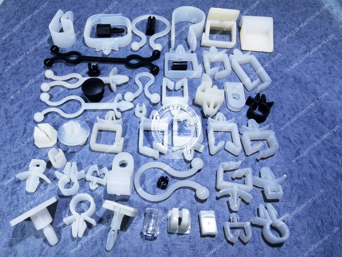
A snap-fit PCB support is a molded component designed to maintain a controlled separation between a printed circuit board and another board, chassis, enclosure, or mounting surface.
One or both ends incorporate flexible retention features that engage corresponding mounting holes or edges.
Depending on the design, the component may provide several functions simultaneously:
Maintain PCB elevation
Support board weight
Reduce local board movement
Position the PCB during assembly
Retain the board mechanically
Separate the PCB from conductive chassis surfaces
Eliminate separate nuts and screws
Simplify high-volume assembly
The terms PCB support, circuit board support, PCB spacer, PCB standoff, mounting pillar, and board support are sometimes used broadly in industrial catalogs.
For engineering purposes, the actual retention geometry matters more than the catalog name.
Snap-fit PCB supports and threaded standoffs solve related but different assembly problems.
A threaded standoff typically uses screws or threaded studs to create a mechanically controlled board mounting interface.
A snap-fit support relies on flexible molded features to engage the PCB, chassis, or both.
Snap-fit designs can provide:
Faster assembly
Reduced loose hardware
Fewer assembly operations
Tool-free installation in suitable designs
Lower component count
Electrical isolation
Threaded standoffs may be preferable when an assembly requires:
Higher controlled clamp load
Frequent board removal
Defined screw torque
High mechanical load
Strong resistance to accidental release
Metal grounding through the mounting hardware
The correct architecture should therefore be selected according to the complete assembly requirement rather than simply replacing one type with another.
Arrowhead-style PCB supports use flexible locking features that compress as they enter a mounting hole and expand after insertion.
Depending on the design, an arrowhead may engage:
The PCB
The chassis
Both sides of the assembly
These supports can provide rapid push-in installation and positive mechanical retention.
They are commonly used where rear-side tool access is limited or where high assembly speed is important.
Barbed supports use ribs or flexible retaining features that create interference with a mounting hole.
Their retention mechanism can resemble other barbed plastic fasteners,
but PCB applications introduce additional requirements such as controlled board elevation and avoidance of excessive stress around the mounting hole.
Snap-lock supports incorporate a molded locking head that engages the circuit board after insertion.
Depending on the geometry, the locking head may be permanent, semi-removable, or intentionally releasable.
These designs are useful where the PCB must remain securely positioned during:
Shipping
Equipment installation
Fan vibration
Service handling
Normal equipment operation
Some circuit board supports use snap-lock retention at both ends.
One end engages the chassis while the other engages the PCB.
This can eliminate threaded hardware entirely in suitable applications.
Both interfaces must be validated independently because PCB thickness and chassis thickness can be different.
Some supports positively lock to the chassis but use a non-locking support feature at the PCB, or vice versa.
A resting end can provide vertical support without fully retaining the board.
This can be useful where thermal expansion, assembly sequencing, or service access makes full locking at every support point undesirable.
Not every circuit board support requires a drilled PCB mounting hole.
Edge-locking designs engage the edge of the board or a designated board feature.
These can be useful when:
Board area is limited
Mounting holes are undesirable
Rapid board installation is required
PCB edge geometry can be controlled
Board-edge thickness and local component clearance become important selection parameters.
Some PCB mounting hardware uses rotational or bayonet-style engagement rather than direct axial snap installation.
These designs can provide positive retention while allowing controlled installation or removal.
The chassis interface must be designed specifically for the locking geometry.
One of the most important differences between ordinary panel clips and PCB supports is that many PCB standoffs must satisfy two separate mechanical interfaces.
The board-side interface can depend on:
PCB hole diameter
PCB thickness
Hole tolerance
Local copper clearance
Locking-head geometry
Board material
Required removal method
The chassis-side interface can depend on:
Chassis hole diameter
Chassis thickness
Hole shape
Burr condition
Panel material
Coating thickness
Locking-barb geometry
Required pull-out retention
A support can fit the PCB correctly while being unsuitable for the chassis, or vice versa.
For this reason, second-source qualification should never be based only on standoff height and overall appearance.
There is no single mounting-hole diameter that applies to all snap-fit PCB supports.
The correct PCB hole depends on the specific locking-head geometry.
Depending on the product family, board-side retention may use:
Arrowhead feature
Snap-lock head
Split post
Barbed post
Edge retention
Resting support
Other proprietary geometry
The PCB mounting hole should therefore be taken from the approved component drawing or validated application design.
Assuming a universal nominal PCB hole can lead to:
Excessive insertion force
Cracking around the hole
Poor board retention
Excessive board movement
Difficult removal
Damaged locking features
The chassis mounting hole controls the engagement of the lower locking feature.
If the hole is too large:
Pull-out retention may decrease
The support may rotate
The PCB may move
Vibration behavior may become inconsistent
If the hole is too small:
Installation force can increase
Locking barbs can be damaged
The chassis can deform
The support may not seat completely
Hole tolerance should therefore be evaluated across the actual production range rather than only at nominal diameter.
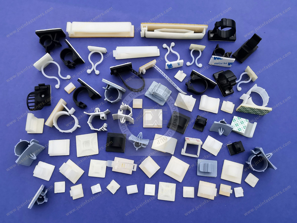
Chassis mounting features can include:
Round holes
Slotted holes
Keyed holes
Rectangular openings
Bayonet interfaces
The support must be selected for the actual geometry.
A component designed for a round hole should not automatically be used in a slot merely because the slot width appears dimensionally compatible.
Slots can change:
Retention
Rotation
Positional freedom
Assembly alignment
PCB thickness influences the engagement of snap-lock and arrowhead features.
If the board is thicker than the intended range:
Locking features may not fully engage
Installation force may increase
Board stress may increase
If the board is too thin:
Excessive axial play may occur
Rattle may develop
The board may not be securely retained
The actual PCB thickness and tolerance should therefore be included in the component specification.
PCB thickness and chassis thickness are independent variables.
A double-locking PCB support may have one grip requirement for the circuit board and another for the sheet-metal or plastic chassis.
For second-source qualification, both interfaces must be reviewed.
Standoff height determines the vertical distance between the PCB and its mounting surface.
This dimension affects:
Component clearance
Airflow
Electrical spacing
Connector alignment
Cable routing
Heat-sink clearance
Enclosure height
Service access
The required standoff height should therefore be derived from the complete mechanical stack-up.
Modern PCBs frequently contain components on both sides of the board.
Under-board features may include:
Surface-mount components
Solder joints
Connectors
Test points
Heat sinks
Shielding
Wiring
A PCB support must provide adequate clearance not only at the nominal board plane but also around its head and locking features.
A support with the correct overall height can still interfere with a component if its head diameter or shoulder geometry occupies restricted PCB space.
Large circuit boards can flex under:
Their own weight
Heavy components
Connector insertion
Cable loads
Heat sinks
Shipping vibration
Service handling
Support placement therefore affects mechanical reliability.
Insufficient support can allow excessive board deflection, while poorly positioned supports can introduce localized stress.
Support layout should consider:
Board dimensions
Board thickness
Heavy component locations
Connector forces
Heat sinks
Cable loads
Cutouts
Mounting-hole locations
Expected vibration
The objective is not simply to maximize the number of supports.
The objective is to control board movement and distribute mechanical loading appropriately.
An often-overlooked mechanical load occurs when external connectors are plugged into or removed from a PCB.
Connector insertion or extraction can create substantial local force and bending moment.
Supports positioned near:
I/O connectors
Power connectors
Backplane interfaces
Large terminal blocks
may therefore play a more important mechanical role than supports located in lightly loaded areas.
PCB support layout should be evaluated together with connector mechanics.
A locking support should retain the board without introducing excessive local stress around the mounting hole.
Potential problems include:
Board cracking
Hole-edge damage
Excessive bending
Local laminate stress
Damage to nearby traces or pads
PCB layout teams should maintain appropriate keep-out zones around mounting features according to the board design and electrical requirements.
PA66 is widely used for molded PCB hardware because suitable grades can provide a useful combination of:
Stiffness
Toughness
Fatigue resistance
Electrical insulation
Moldability
Low weight
It is commonly found in:
PCB supports
Standoffs
Spacers
Card guides
Cable-management components
Insulating hardware
However, the term PA66 does not establish a particular flame rating, thermal rating, moisture behavior, or electrical certification by itself.
The exact resin grade matters.
Electronic equipment may require polymer components with specified flammability characteristics.
UL 94 classifications such as V-0 or V-2 are associated with specific tested materials and test conditions.
A critical engineering distinction is:
PA66 does not automatically mean UL 94 V-0 or V-2.
The applicable classification depends on the specific resin formulation and tested specimen thickness.
When a project requires a defined flammability classification, engineering and procurement teams should specify:
Required rating
Resin grade
Relevant thickness information
Required supporting documentation
A generic statement such as "nylon PCB support" is not sufficient to establish flame performance.
Even when a PCB support is manufactured from a resin carrying a particular UL 94 classification, the final equipment remains subject to its applicable system-level design and certification requirements.
Component material data should therefore be treated as supporting engineering information rather than an automatic certification of the complete product.
PA66 is hygroscopic and absorbs moisture from the surrounding environment.
Moisture conditioning can affect:
Dimensions
Stiffness
Toughness
Locking-feature flexibility
Insertion force
Pull-out behavior
This can become relevant in high-density arrays where multiple PCB supports must align simultaneously with several mounting holes.
Small dimensional changes across one support may appear insignificant, but tolerance accumulation across a large PCB can affect assembly.
Engineering validation should therefore consider the actual environmental condition when dimensional sensitivity is high.
A PCB, metal chassis, and polymer support can have different thermal-expansion behavior.
When a large circuit board is rigidly constrained at many locations, thermal cycling can generate mechanical stress because the board, supports, and chassis do not necessarily expand at the same rate.
Depending on the assembly, engineers may need to consider whether every support should provide identical rigid lateral constraint.
Some designs benefit from a combination of:
Locating supports
Locking supports
Resting supports
Controlled-clearance features
This allows the assembly to maintain position without unnecessarily over-constraining the board.
Adding more locking supports does not automatically create a better assembly.
Excessive constraint can make manufacturing tolerance stack-up more difficult and can increase thermal or mechanical stress.
A useful design question is:
Which support locations must locate the PCB, which must retain it, and which only need to support it vertically?
Separating these functions can improve assembly robustness.
Servers, telecommunications equipment, power electronics, industrial controls, automotive electronics, and other equipment may expose PCBs to continuous vibration.
Sources can include:
Cooling fans
Pumps
Vehicle vibration
Machinery
Shipping
Equipment handling
Plastic supports can help control board movement, but vibration performance depends on:
Support spacing
Board stiffness
Support geometry
Locking fit
Component mass
Chassis stiffness
Temperature
Material condition
The term "vibration resistant" should therefore not be treated as a universal property of all snap-fit PCB supports.
AI servers and high-performance computing equipment combine dense electronics, substantial cooling airflow, high component density, and extensive cable routing.
Plastic PCB hardware can be used in selected applications for:
Control boards
Power-management boards
Auxiliary PCBs
Fan-control assemblies
Sensor boards
Network electronics
Cable-management systems
Internal electronic modules
Engineering considerations can include:
Airflow
Board clearance
Serviceability
Flame-retardant material requirements
Operating temperature
Fan vibration
Dense connector layouts
Cable routing
For high-density equipment, small mechanical components can have a disproportionate effect on assembly efficiency and service access.
Snap-fit PCB supports can be used in:
Routers
Switches
Communication cabinets
Radio equipment
Optical network equipment
Power modules
Control boards
Tool-free mounting can reduce assembly operations where the product architecture permits snap-fit retention.
Power electronics assemblies may include:
Inverters
Power supplies
UPS systems
AC/DC converters
DC/DC converters
Power distribution equipment
Motor drives
PCB support selection should consider:
Temperature
Electrical spacing
Component mass
Heat sinks
Vibration
Flammability requirements
Serviceability
Large power components can create localized PCB loads that require deliberate support placement.
Semiconductor manufacturing and process equipment can contain large numbers of:
Control boards
Sensor modules
Power electronics
Communication boards
Instrumentation assemblies
Depending on the environment, requirements may include:
Electrical insulation
Material cleanliness
Chemical compatibility
Temperature stability
Low particle generation
Customer-specific material controls
These requirements should be specified during RFQ rather than assumed from the generic PCB support product family.
PCB supports are used in:
PLCs
Servo drives
Robot controllers
I/O modules
Sensor equipment
Machine controls
Industrial computers
Industrial environments may add:
Vibration
Elevated temperature
Dust
Long service life
Maintenance requirements
Support design should reflect the complete equipment environment.
Potential applications include:
Electronic control units
Infotainment systems
Sensor modules
Power-control equipment
Charging electronics
Battery-management electronics
Interior electronics
Automotive applications can involve substantial vibration and thermal cycling.
Material and retention requirements should therefore be evaluated against the specific mounting location.
Plastic PCB supports can be used in diagnostic, laboratory, analytical, and electronic medical equipment.
Potential advantages include:
Electrical insulation
Low weight
Clean assembly
Reduced loose hardware
However, medical applications can have customer-specific requirements for materials, cleaning, sterilization, documentation, or regulatory controls.
These requirements must be defined by the OEM and should not be inferred from the fastener material alone.
Plastic PCB supports can provide non-conductive mechanical separation between a circuit board and conductive chassis.
This can help avoid direct metallic contact.
However, the presence of a plastic support does not by itself establish the required:
Creepage distance
Clearance distance
Dielectric withstand
Equipment safety classification
These depend on the complete electrical design, voltage, pollution degree, material properties, applicable standards, geometry, and other system-level factors.
The PCB support should therefore be treated as one element within the insulation architecture.
Standoff height is a mechanical dimension.
Electrical clearance and creepage are electrical-safety design parameters.
They may be related geometrically, but they are not interchangeable.
A 10 mm mechanical standoff does not automatically provide 10 mm of compliant creepage distance,
because creepage follows a surface path and can be influenced by geometry, materials, contamination, and other features.
Electrical engineers should establish the applicable requirement separately.
PCB supports vary substantially in removal behavior.
Some are intended for:
Permanent assembly
One-time snap installation
Limited service removal
Repeated board access
A support that can physically be forced out is not necessarily reusable.
Before specifying a support for serviceable equipment, determine:
Which end releases
Required release tool
Accessibility
Risk of damaging the PCB
Risk of breaking the support
Expected service cycles
This is especially important in servers, telecommunications equipment, industrial controls, and instrumentation where field replacement may be required.
Possible causes include:
Undersized chassis hole
Excessive burr
Incorrect support geometry
Excessive coating buildup
Misalignment
Material condition
Investigate:
Hole size
Sharp edges
Excessive insertion force
Polymer condition
Low temperature
Incorrect part
Possible causes include:
Incorrect PCB thickness
Wrong locking-head geometry
Incorrect standoff height
Component interference
Multiple-hole misalignment
Investigate:
Incorrect locking range
Oversized hole
Thin PCB
Incomplete seating
Excessive support clearance
Possible causes include:
Incorrect support height
Tolerance stack-up
Misaligned holes
Excessive locking force
Over-constrained support layout
Investigate:
Insufficient chassis engagement
Incorrect PCB engagement
Hole tolerance
Component mass
Support placement
Material behavior
Actual vibration load
Specify:
PCB thickness
PCB thickness tolerance
Board dimensions
Mounting-hole diameters
Hole tolerances
Component keep-out zones
Heavy component locations
Connector locations
Specify:
Chassis material
Chassis thickness
Mounting-hole diameter
Hole shape
Hole tolerance
Coating
Burr condition
Consider:
Under-board components
Solder joints
Airflow
Wiring
Heat sinks
Chassis geometry
Electrical spacing
Choose among:
Locking/locking
Locking/resting
Arrowhead
Barbed
Edge-locking
Bayonet
Threaded standoff
Other mounting architecture
Consider:
Temperature
Humidity
Vibration
Chemicals
Flammability requirements
Electrical requirements
Determine whether the PCB must be:
Permanently installed
Occasionally removed
Frequently serviced
Test representative production boards and chassis components rather than validating the support in isolation.
Large boards should be evaluated as mechanical structures.
Useful design inputs include:
Board length and width
Thickness
Component mass distribution
Connector loads
Heat-sink locations
Vibration
Orientation
Supports may be required not only around the perimeter but also in central regions where board deflection could become significant.
The appropriate number and spacing cannot be defined by one universal formula because PCB constructions and loading conditions vary substantially.
For an existing PCB support, provide:
Existing manufacturer
Part number
Physical sample
Product drawing
PCB hole diameter
PCB thickness
Chassis hole diameter
Chassis thickness
Standoff height
Material requirement
Cross-reference evaluation should compare:
Overall height
Functional standoff height
PCB locking geometry
Chassis locking geometry
Head and shoulder dimensions
Hole compatibility
Panel thickness compatibility
Material
Color
Installation behavior
Removal behavior
Two PCB supports with the same nominal standoff height are not necessarily interchangeable.
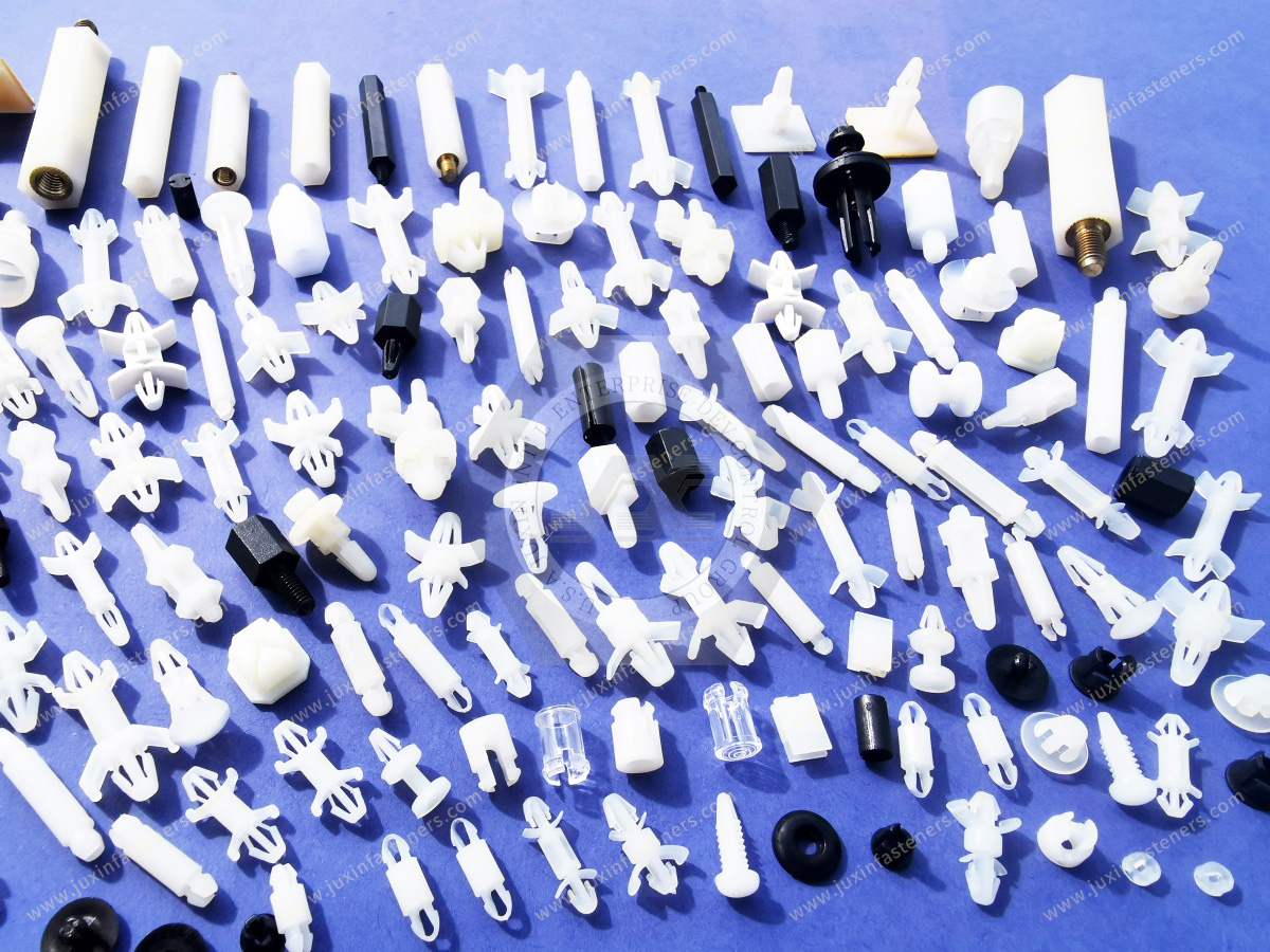
PCB support geometries can look extremely similar in photographs.
Small differences in:
Barb angle
Locking-head diameter
Shoulder thickness
Shank diameter
Standoff height
Release geometry
can change assembly behavior significantly.
For second-source projects, an existing manufacturer part number, drawing, or physical sample is generally much more useful than a photograph alone.
Standard components are preferred where they satisfy the required interface.
Custom development may be considered when the application requires:
Non-standard standoff height
Unique PCB thickness
Special chassis interface
Restricted head diameter
Special locking geometry
Edge retention
Custom material
Custom color
Integrated cable-management feature
Customer-specific dimensions
Custom support development should evaluate both mechanical interfaces and the complete PCB/chassis tolerance stack.
Depending on the application, sample evaluation can include:
PCB insertion
Chassis insertion
Seating confirmation
Standoff-height verification
Pull-out retention
Board removal
Reinstallation
Board deflection
Vibration
Temperature conditioning
Humidity conditioning
Dimensional inspection
For multi-support arrays, testing should use the complete PCB whenever possible because individual-support testing does not reveal array-level alignment and tolerance issues.
For efficient evaluation, provide as much of the following information as possible:
Existing manufacturer part number
Physical sample
2D drawing
3D model
PCB thickness
PCB hole diameter and tolerance
Chassis material
Chassis thickness
Chassis hole diameter and tolerance
Hole shape
Required standoff height
Overall-height limitation
Head-diameter limitation
Required retention type
Required material
Resin grade, if controlled
Required UL 94 classification, if applicable
Color
Operating temperature
Humidity exposure
Vibration requirements
Chemical exposure
Service-removal requirement
Required compliance documentation
Required material documentation
Lot traceability
Order quantity
Estimated annual volume
Packaging requirements
If the exact resin grade is unknown, provide the required performance and existing component information rather than assuming that all nylon PCB supports use the same material.
Depending on the project, requested documentation may include:
Product drawing
Dimensional inspection report
Material information
Resin datasheet
Applicable flammability documentation
RoHS declaration
REACH declaration
Lot traceability
Sample approval documentation
Customer-specific quality records
Documentation requirements should be identified during RFQ and supplier qualification.
For an existing component:
Existing Part Number or Sample → PCB Interface Review → Chassis Interface Review → Standoff Height Verification
→ Material Review → Candidate Cross-Reference → Sample Evaluation → Complete Assembly Validation → Second-Source Qualification → Production RFQ
For a new electronic assembly:
PCB Layout → Chassis Design → Required Board Elevation → Mechanical Load Review → Support Architecture Selection → Material Selection → Prototype → Assembly Validation → Production Approval
For a custom component:
2D/3D Requirement → Dual-Interface Review → Material and Manufacturability Review → Prototype or Sample → PCB/Chassis Testing → Qualification → Production RFQ
This approach prevents PCB supports from being treated as generic plastic spacers and instead evaluates them as functional mechanical interfaces within an electronic system.
Juxin Fasteners supports engineering, procurement, supplier-development, and supply-chain teams sourcing standard and custom plastic electronic hardware, including:
Snap-fit PCB supports
Circuit board supports
PCB spacers
PCB standoffs
PCB mounting pillars
Arrowhead PCB supports
Snap-lock PCB supports
Edge-locking PCB supports
Nylon spacers
Plastic standoffs
Nylon machine screws
Plastic washers
Cable-management hardware
Custom molded plastic components
For standard sourcing, provide the PCB thickness, PCB hole, chassis hole, chassis thickness, standoff height, material, and required quantity.
For second-source qualification, send the existing part number, drawing, CAD model, or physical sample.
For new or custom applications, provide the PCB/chassis interface dimensions, required board elevation,
environmental requirements, material requirements, and available engineering drawings.
Juxin Fasteners can support dimensional review, product cross-reference, sample evaluation, custom component development, second-source qualification,
and production RFQ requirements for global electronics OEM programs.
Email: info@juxinfasteners.com
Website: www.juxinfasteners.com
Previous: Cable & Wire Management Hardware
 MORE NEWS

Sep. 27, 2026

Sep. 27, 2026

Sep. 27, 2026
Contact Us
Tel.:
+86 020 8621 0320
+86 020 3121 6067
E-mail:
Technical Support:
Navigation
SEND INQUIREY