
Call Us
+86 136 6007 9809
Call Us
+86 136 6007 9809

Sep. 27, 2026
Strain relief bushings, cord grips, and molded cable strain relief components are used where flexible power cords,
electrical cables, or wiring enter equipment housings, appliances, electrical enclosures, machinery, and other assemblies.
Their engineering function goes beyond covering a sharp panel edge.
When an external cable is pulled, pushed, twisted, bent, or repeatedly handled, those mechanical loads can otherwise be transferred toward internal terminals,
connectors, splices, solder joints, or conductor terminations. A properly selected strain relief system helps manage those external forces at the equipment-entry interface.
This distinction is important:
A panel hole protector primarily protects the cable from the panel edge. A strain relief bushing is intended to control mechanical loads transmitted through the cable.
Selecting the correct strain relief bushing therefore requires more than matching a nominal cable outside diameter.
Engineers should evaluate the complete interface between:
cable construction
cable outside dimensions
cable jacket material
jacket compressibility
strain relief gripping geometry
panel cutout
panel thickness
installation orientation
axial pull
push forces
twisting or rotational loads
bending near the entry
polymer behavior
temperature
moisture
long-term stress relaxation
applicable equipment requirements
For procurement and supplier-development teams, this also means that two strain relief bushings with similar external dimensions should not automatically be treated as interchangeable.
Juxin Fasteners supplies standard and custom plastic fastening components for industrial OEM applications and supports strain relief projects using existing manufacturer part numbers,
physical samples, cable specifications, panel drawings, 2D drawings, 3D CAD models, material requirements, and application information.
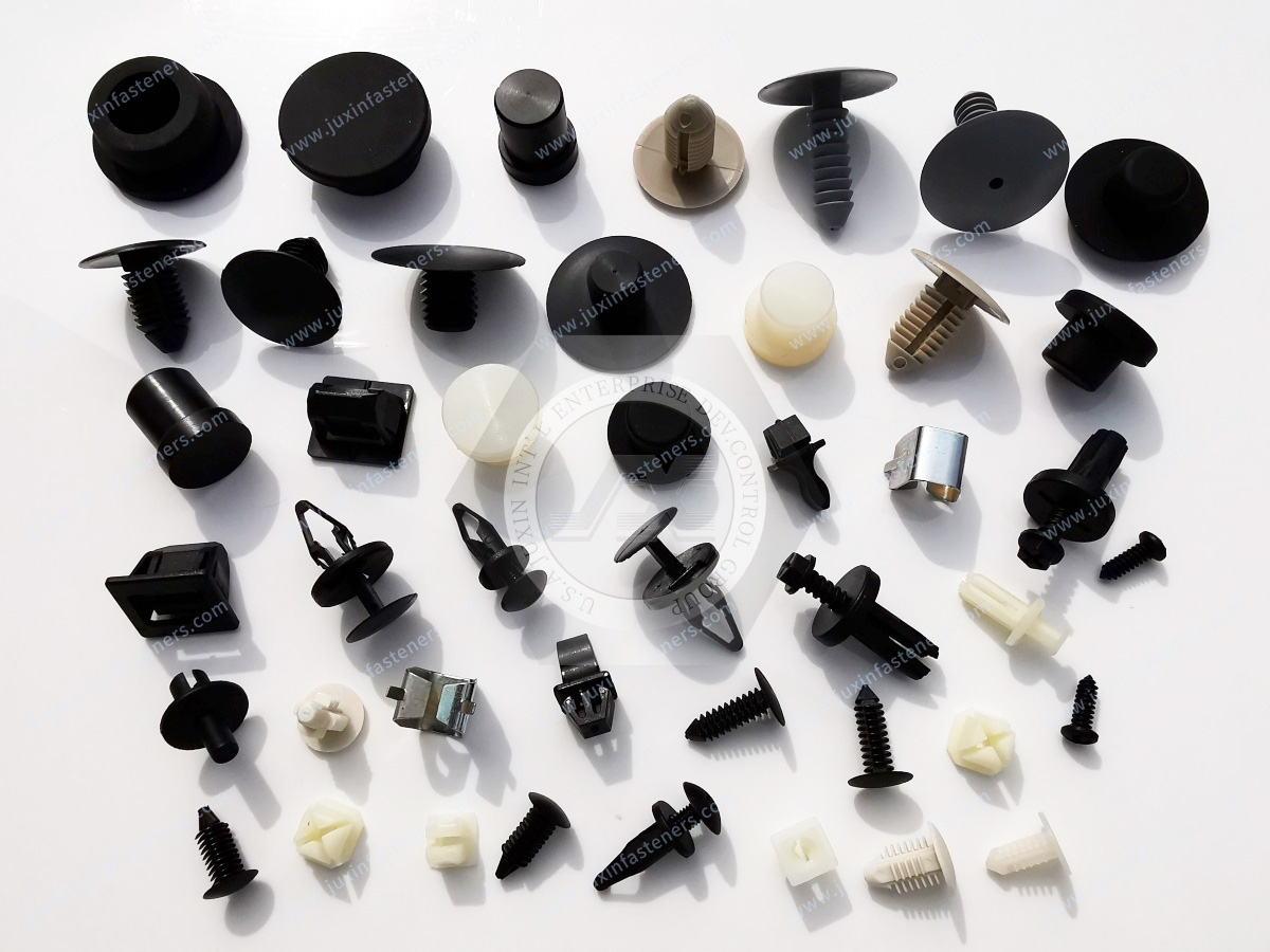
A strain relief bushing is a mechanical cable-entry component designed to help prevent external loads applied to a cable from being transferred directly to internal electrical connections.
Common procurement and engineering search terminology includes:
strain relief bushing
cable strain relief
cord grip
nylon strain relief
power cord strain relief
panel mount strain relief
push-in strain relief bushing
cord protection connector
cable entry bushing
strain relief connector
Depending on the design, the component may grip, compress, bend, redirect, or mechanically constrain the cable jacket while simultaneously engaging the equipment panel.
The cable, bushing, and panel therefore form a functional mechanical system.
These product categories are frequently grouped together but should not be treated as equivalent.
A conventional snap bushing or panel hole protector primarily creates a protective interface between the cable and the edge of a panel cutout.
It may provide electrical separation from the metal edge, but it does not automatically provide meaningful cable strain relief.
A strain relief bushing is designed to mechanically engage the cable and panel so external cable loads can be managed at the entry point.
Its cable-contact geometry is therefore functionally important.
Cable glands use a different mechanical architecture and may combine cable retention with environmental sealing or other functions depending on the specific design.
A standard strain relief bushing should not automatically be treated as a liquid-tight cable gland.
The engineering question should therefore begin with:
Does the application require edge protection, mechanical strain relief, environmental sealing, or a combination of these functions?
The mechanical function can be understood through a simple load path.
Without effective strain relief:
External Cable Load → Cable Jacket / Conductors → Internal Termination
With an appropriately designed and validated strain relief interface:
External Cable Load → Cable Jacket → Strain Relief → Panel / Housing
The objective is to redirect or reduce the mechanical load reaching sensitive internal connections.
This is why strain relief performance cannot be determined by the plastic component alone.
The complete system includes:
Cable + Strain Relief Geometry + Panel Cutout + Panel Thickness + Installation Condition
Different cable-entry architectures require different strain relief designs.
Push-in strain relief bushings can use hinged, multi-piece, interlocking, or other molded geometries that engage the cable and panel during installation.
Depending on the design, the bushing may compress or constrain the cable jacket while locking into the panel opening.
The resulting retention depends on the relationship between:
cable geometry
cable compressibility
internal gripping profile
panel cutout
panel thickness
polymer condition
Right-angle designs redirect the cord close to the equipment housing.
These can be useful where:
equipment must sit close to a wall
rear clearance is limited
cord routing must be controlled
excessive bending near the cable entry should be avoided
However, the bend geometry must still be appropriate for the specific cable construction.
A right-angle strain relief should not create an excessively tight bend that damages or overstresses the cable.
Round power cables require internal gripping geometry compatible with the cable's finished outside diameter and jacket characteristics.
Round cables that share the same nominal OD can still differ in:
jacket material
jacket hardness
compressibility
conductor construction
reinforcement
surface friction
Therefore, nominal cable OD alone does not prove strain-relief compatibility.
Flat parallel cords require a different internal cavity than round cable.
Examples may include appliance cord constructions such as selected SPT-type cords where appropriate to the equipment design.
For flat cable, engineers may need to define both:
cable width
cable thickness
The profile orientation inside the bushing can also affect retention.
Some strain relief components use internal geometry developed around a specific cord construction.
This means a component designed for one cable family should not automatically be used with another cable simply because their maximum outside dimensions appear similar.
Cable outside diameter is one of the first dimensions engineers and buyers use when selecting a cord grip.
It is important, but it does not describe the complete cable.
Two cables with the same nominal OD may react differently under clamping because of differences in:
jacket polymer
jacket hardness
jacket wall thickness
conductor arrangement
fillers
shielding
reinforcement
compressibility
surface texture
A relatively soft cable jacket may deform substantially under a gripping feature, while a stiffer cable may require a different interface to achieve suitable retention without damage.
Therefore:
Same Cable OD ≠ Same Strain Relief Performance
This is one of the most important considerations when qualifying a replacement strain relief bushing.
Strain relief requires mechanical interaction with the cable, but maximum compression is not necessarily desirable.
Insufficient engagement may allow:
cable slippage
rotation
movement under push loading
load transfer to internal connections
Excessive compression may cause:
jacket deformation
conductor distortion
insulation damage
difficult assembly
incomplete bushing closure
long-term cable damage
The correct objective is controlled retention appropriate to the cable and application.
For this reason, sample evaluation should use the actual production cable whenever possible.
Many strain relief bushings do not install into a generic circular hole.
Depending on the design, the required cutout may be:
round
oval
rectangular
keyed
double-D
another application-specific profile
Non-round features can serve several purposes.
They may:
establish orientation
prevent bushing rotation
support locking geometry
help resist twisting loads applied through the cable
This means that a strain relief bushing cannot be selected correctly without understanding the equipment panel.
A cable can experience rotational loads when:
users move equipment
plugs are inserted or removed
cords are repositioned
equipment is serviced
the cable is accidentally twisted
If the bushing rotates inside the panel, twisting may be transferred toward internal wiring or terminations.
Keyed or non-round panel cutouts can help manage this behavior when they are part of the component design.
However, rotational performance depends on:
cutout geometry
cutout tolerance
panel thickness
bushing geometry
cable construction
installation condition
Anti-rotation should therefore be validated as part of the complete assembly.
Like other snap-fit panel hardware, strain relief bushings are designed around particular panel-interface conditions.
If the panel is too thick for the selected component:
locking features may not fully engage
installation force may increase
the component may not seat correctly
retention may be reduced
If the panel is too thin:
excessive axial movement may occur
anti-rotation engagement may change
the bushing may not be retained as intended
Panel thickness must therefore be evaluated together with the panel cutout.
Nominal cutout dimensions alone are not enough for a critical strain-relief application.
Actual production panels can vary because of:
stamping tolerance
punching
laser cutting
casting
machining
coating
burr condition
These variations can affect insertion and retention.
When a strain relief component is being second-sourced, procurement and engineering teams should compare the candidate against the actual panel specification rather than only the nominal catalog cutout.
Panel-edge condition can influence both installation and cable protection.
Excessive burrs may:
interfere with bushing seating
damage locking features
increase insertion force
alter retention
create local cable hazards if the bushing does not completely cover the edge
A strain relief component should not be used as a substitute for controlled panel manufacturing and appropriate deburring.
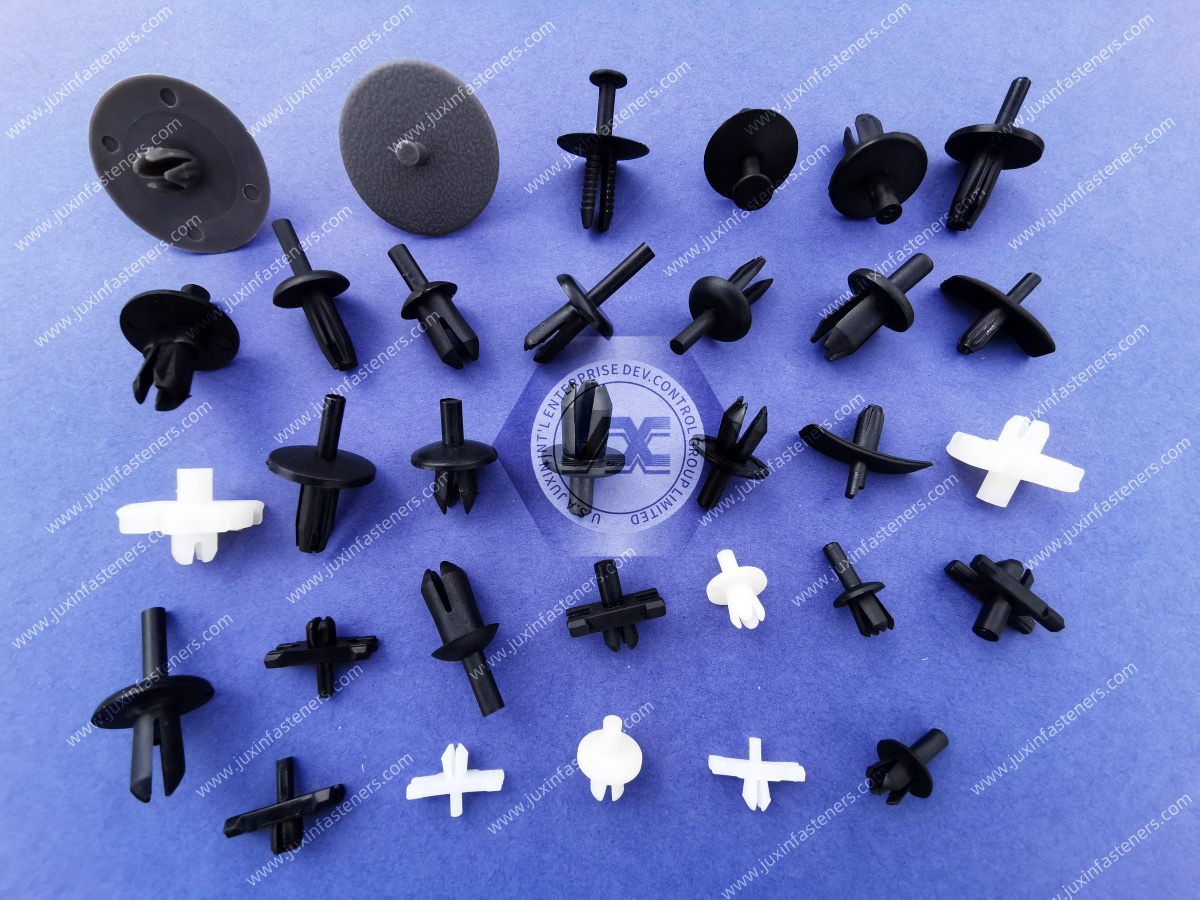
The polymer must support both installation deformation and long-term mechanical retention.
PA66 is commonly used for many molded cable-management and strain relief components because suitable grades can provide a useful combination of stiffness, toughness, wear behavior, and moldability.
However, PA66 is not automatically the material for every strain relief bushing.
The actual polymer and resin grade should be confirmed for the specific component and application.
Electrical equipment may require polymer materials with specified flammability performance.
Where a particular UL 94 classification or another flame-performance requirement is specified, it must be associated with the actual resin grade and applicable material conditions.
A generic statement such as “PA66” or “nylon” does not establish V-0, V-2, or any other flammability classification.
The required performance should therefore be specified during the RFQ and confirmed for the actual material.
Polyamides such as PA6 and PA66 are hygroscopic.
They absorb moisture from the surrounding environment.
Moisture conditioning can affect:
dimensions
stiffness
toughness
strength
flexibility
installation behavior
locking-feature response
cable gripping behavior
creep
stress relaxation
Conditioned nylon may behave differently from dry-as-molded nylon.
However, this should not be simplified into a claim that moisture automatically improves strain relief performance.
The effect depends on:
resin grade
geometry
conditioning state
cable interface
environmental conditions
For applications where strain relief retention is safety-critical, the expected environmental condition should be considered during validation.
A strain relief bushing can maintain continuous mechanical pressure against a cable jacket.
That makes long-term polymer behavior especially important.
Polymers are viscoelastic materials.
Under sustained deformation or load, their mechanical response can change with time.
Potential factors include:
creep
stress relaxation
temperature
moisture
initial deformation
resin grade
cable compressibility
component geometry
service duration
A strain relief system that provides strong initial grip should not automatically be assumed to provide identical retention throughout its service life.
Long-term suitability must be considered according to the actual application.
Temperature can influence both sides of the interface.
The strain relief polymer may become more compliant or experience accelerated long-term relaxation, depending on the material and conditions.
At the same time, the cable jacket can also change mechanical behavior with temperature.
This means the interface is not simply:
Plastic Bushing vs. Cable Diameter
It is:
Polymer Bushing Behavior + Cable Jacket Behavior + Temperature + Time
This is particularly relevant in:
commercial cooking equipment
power electronics
HVAC systems
lighting
industrial machinery
equipment with internal heat sources
Temperature capability should be established from the actual component and cable specifications rather than a generic nylon rating.
A common procurement question is:
“What is the pull-out force of this strain relief?”
That question cannot always be answered meaningfully with one universal component value.
Pull retention can depend on:
cable type
cable dimensions
jacket material
jacket hardness
bushing geometry
panel cutout
panel thickness
installation
conditioning
temperature
test method
The same strain relief component can perform differently with different cables.
Therefore, when pull retention is important, the production cable + production-equivalent panel + selected strain relief should be evaluated together.
Electrical equipment may be subject to cable-retention, strain-relief, or cord-anchorage requirements under applicable product safety standards.
Depending on the equipment and target market, requirements may come from standards or certification programs associated with organizations such as:
UL
CSA
IEC
EN or other adopted standards
The required test method, force, duration, cable condition, displacement criterion, torque or twist requirement, and acceptance criteria depend on the applicable equipment standard.
There is no universal pull-test number that applies to every strain relief bushing and every electrical product.
Component selection should therefore begin with the applicable equipment requirement.
This distinction is important for both engineering and procurement.
Using a particular polymer grade or strain relief design does not automatically certify the finished appliance or equipment.
Final compliance may depend on:
complete equipment architecture
cable type
panel construction
installation method
material documentation
component recognition where applicable
required tests
certification-body evaluation
Supplier documentation can support the customer's compliance process, but the finished system must be evaluated according to its applicable requirements.
External cable loading is not always tensile.
A cable can also be pushed into an enclosure.
If inward movement is excessive, it may:
disturb internal routing
create conductor slack
contact hot or moving components
load terminals from another direction
Where the equipment requirement includes inward displacement or push resistance, this should be evaluated during validation.
Twisting can be another important load mode.
The strain relief and panel interface may need to resist cable rotation so torsional load is not transferred to internal conductors.
Performance depends on the complete system and should not be inferred solely from the presence of a keyed cutout.
Strain relief and flex protection are related but not identical.
Some designs include an extended flexible section that controls how a cable bends near the equipment entry.
This can reduce severe localized bending.
However, bend performance depends on:
cable construction
bend radius
flex frequency
protector geometry
material
temperature
A strain relief bushing without an extended flex section should not automatically be expected to perform as a dynamic bend protector.
Strain relief components may encounter:
cleaning agents
oils
grease
food-service chemicals
coolants
moisture
industrial fluids
UV exposure in selected applications
Compatibility should be evaluated for the specific polymer grade and actual exposure.
No generic nylon material should be described as universally resistant to industrial chemicals.
A practical strain relief selection process can follow:
Equipment Requirement → Cable → Panel → Load Modes → Environment → Material → Geometry → Validation
Identify the applicable mechanical and safety requirements.
Determine whether the component needs to provide:
pull resistance
push resistance
twist resistance
bend control
edge protection
another specified function
Define:
cable family
cable profile
outside dimensions
tolerance
jacket material
compressibility
construction
Define:
cutout geometry
cutout dimensions
tolerance
panel thickness
panel material
edge condition
Identify whether the cable may experience:
axial pull
inward push
twisting
bending
vibration
repeated handling
Evaluate:
temperature
moisture
chemical exposure
UV exposure where relevant
Select the polymer grade according to the actual mechanical, environmental, flammability, and application requirements.
Match the cable gripping interface and panel retention geometry.
Test the actual or production-equivalent assembly according to the applicable customer and equipment requirements.
This approach is more reliable than selecting a strain relief from cable OD alone.
Failure analysis can provide useful guidance during both product design and second-source qualification.
Possible contributors include:
incorrect cable size
cable jacket too stiff or too compliant for the selected geometry
inadequate gripping engagement
incorrect bushing
installation problem
panel mismatch
polymer relaxation
Possible contributors include:
cable too large
incompatible internal profile
excessive interference
wrong strain relief design
cable construction not suited to the component
Possible contributors include:
incorrect panel cutout
panel too thick
excessive burr
incorrect cable size
cable profile mismatch
component orientation error
Possible contributors include:
incorrect cutout
excessive cutout tolerance
insufficient anti-rotation engagement
panel mismatch
wrong cross-reference
Possible contributors include:
excessive installation deformation
incorrect panel geometry
polymer condition
environmental aging
low-temperature installation
component damage
Possible contributors include:
creep
stress relaxation
temperature
moisture conditioning
cable jacket deformation
unsuitable component/cable combination
These examples demonstrate why an existing strain relief should be qualified as a system interface, not simply copied by external dimensions.
Power cords entering appliances often require controlled strain relief to protect internal electrical connections from user handling.
The selected component should be evaluated with the actual production cord, panel, and applicable equipment requirements.
Commercial ovens, beverage equipment, refrigeration systems, food-preparation machinery, and related equipment may combine:
power cords
elevated temperatures
cleaning chemicals
frequent service
Material and cable-interface selection should reflect the actual environment.
HVAC systems use flexible electrical cables for motors, controls, compressors, fans, pumps, and auxiliary equipment.
Cable-entry hardware may need to account for vibration, temperature, moisture, and service access.
Power supplies, converters, control systems, power electronics, and other electrical equipment may use strain relief bushings where external cables enter enclosures.
Electrical and flame-performance requirements should be identified according to the actual equipment specification.
Machines may use strain relief components for power cables, control wiring, handheld controls, auxiliary equipment, and external electrical connections.
Vibration, oils, repeated handling, and maintenance access can influence selection.
Lighting fixtures and control equipment can require compact cable-entry components where power cords or leads enter metal housings.
Temperature and applicable electrical requirements should be considered.
Selected medical and laboratory equipment may use strain relief components for power and auxiliary cables.
Material, cleaning environment, equipment requirements, and cable-retention criteria should be defined according to the actual product.
Equipment with externally accessible power cords may require reliable cord anchorage because cables can experience movement during installation, relocation, cleaning, and service.
Power and signal cables entering equipment housings may require mechanical retention depending on the product architecture.
The selected strain relief should match the actual cable type and equipment requirements.
This is one of the most important sourcing considerations.
Two components may look nearly identical but differ in:
cable cavity profile
cable size range
gripping geometry
panel cutout
panel thickness compatibility
anti-rotation geometry
locking-feature position
material
resin grade
conditioning
flame-performance classification
dimensional tolerances
For a strain relief component, even a small geometric difference can change the way load is transferred from the cable to the panel.
Therefore, the objective of second-source sourcing is not:
“Find a plastic part that looks the same.”
It is:
“Identify a candidate that reproduces the required cable-to-panel mechanical function and can be validated in the actual assembly.”
A structured second-source process can follow:
Existing Manufacturer / Part Number → Cable Review → Panel Cutout Review → Dimensional Review
→ Material Review → Candidate Cross-Reference → Physical Sample → Assembly Testing → Qualification → Production RFQ
Provide the current supplier and part number whenever available.
Provide:
cable manufacturer and type where relevant
cable profile
OD or width/thickness
jacket material if known
applicable tolerance
Confirm:
cutout shape
dimensions
tolerance
panel thickness
panel material
Critical strain relief dimensions may include:
cable cavity
external body geometry
panel engagement dimensions
locking-feature location
flange dimensions
overall length
orientation features
Confirm any requirements for:
polymer family
resin grade
color
heat stabilization
flame performance
environmental behavior
A replacement should be treated as a candidate until dimensional, material, installation, and performance requirements are reviewed.
Visual similarity alone is not evidence of functional equivalence.
Physical samples can be installed using the actual cable and production-equivalent panel to evaluate:
installation behavior
panel engagement
cable compression
cable movement
pull retention
push behavior
twist resistance
surrounding clearance
cable-jacket condition
Formal testing should follow the customer's applicable product requirements.
Standard products may not fit every cable and enclosure architecture.
Custom development may be appropriate for:
non-standard cable profiles
special panel cutouts
unusual panel thickness
custom anti-rotation geometry
restricted packaging space
specialized cable-routing direction
application-specific resin requirements
customer-specific dimensions
Juxin Fasteners can review drawing-based plastic fastening projects using customer-provided physical samples, cable specifications,
panel drawings, 2D drawings, 3D CAD models, material requirements, and application information.
A custom-development pathway can follow:
Application Requirement → Cable & Panel Interface Review → Material & Geometry Review → Candidate Design → Sample / Prototype → Assembly Validation → Customer Qualification → Production
Industrial sourcing teams may need to define requirements beyond unit dimensions.
Depending on the project, these can include:
drawing revision
cable specification
panel specification
resin requirement
color
dimensional tolerances
required documentation
lot identification
traceability
environmental compliance requirements
packaging
sample quantity
production quantity
estimated annual volume
Where RoHS, REACH, material reports, flammability documentation,
or other compliance information is required, these requirements should be specified during the RFQ and confirmed for the actual component.
They should not be assumed from a generic product description.
For efficient engineering and sourcing evaluation, provide as much of the following information as available:
existing manufacturer
existing part number
physical sample
2D drawing
3D CAD model
cable manufacturer or specification where available
round or flat cable
cable OD
flat-cable width and thickness
cable dimensional tolerance
cable jacket material where known
panel cutout shape
panel cutout dimensions
cutout tolerance
panel thickness
panel material
installation direction
required pull-retention requirement
push requirement where applicable
twist or torque requirement where applicable
bend-control requirement where applicable
operating temperature
moisture exposure
chemical exposure
UV exposure where applicable
vibration conditions
material or resin requirement
color
flame-performance requirement where applicable
applicable equipment standard or test requirement
required documentation
sample quantity
production order quantity
estimated annual volume
packaging requirements
For replacement or second-source projects, providing the existing strain relief + actual production cable + panel drawing gives significantly more useful engineering information than sending only the plastic component.
For a new equipment design:
Equipment Requirement → Cable Definition → Panel Cutout → Load & Environment Review → Material and Geometry Selection → Candidate Component → Sample Assembly → Validation → Production RFQ
For an existing production component:
Existing Part Number / Sample → Cable & Panel Review → Dimensional & Material Review → Candidate Cross-Reference → Sample → Assembly Testing → Second-Source Qualification → Production RFQ
For a custom strain relief:
Cable + Panel + 2D/3D Requirements → Engineering Review → Material & Manufacturability Review → Sample / Prototype → Customer Validation → Qualification → Production
This process connects engineering selection, compliance requirements, supplier development, and procurement into one qualification pathway.
Juxin Fasteners supplies plastic and nylon fastening components for industrial OEM and manufacturing applications,
including strain relief bushings, cable-management hardware, panel-protection components, clips, retainers, spacers, and custom molded plastic fasteners.
Engineering, compliance, procurement, supplier quality, and supplier-development teams can submit an existing manufacturer part number,
competitor part number, physical sample, cable specification, panel drawing, 2D drawing, 3D CAD model, material requirement, application information, and expected purchasing volume for evaluation.
For second-source projects, the goal is to identify a technically appropriate candidate for customer validation rather than assume interchangeability from appearance, cable OD, or nominal panel size alone.
For new and custom projects, defining the actual cable, panel cutout, panel thickness, required load modes, environmental conditions,
and applicable equipment requirements at the beginning of the project creates a more efficient path from engineering review to sampling, qualification, and production RFQ.
Email: info@juxinfasteners.com
Website: www.juxinfasteners.com
Previous: Nylon Screws, Nuts & Washers
 MORE NEWS

Sep. 27, 2026

Sep. 27, 2026

Sep. 27, 2026
Contact Us
Tel.:
+86 020 8621 0320
+86 020 3121 6067
E-mail:
Technical Support:
Navigation
SEND INQUIREY