
Call Us
+86 136 6007 9809
Call Us
+86 136 6007 9809

Mar. 29, 2026
Blind Rivet Nuts: Types, Grip Range, Installation, Materials and OEM Sheet Metal Design Guide
Creating reliable internal threads in thin sheet metal, hollow sections and closed assemblies is a common engineering challenge.
Conventional tapping may not provide sufficient thread engagement in thin materials,
while a separate nut may be impossible to install when the rear side of the component is inaccessible.
Blind rivet nuts, also known as rivet nuts, nutserts or blind threaded inserts,
provide a practical solution by creating a permanent threaded attachment point using installation access from only one side.
They are widely considered for industrial enclosures, machinery, automotive equipment, electrical cabinets,
HVAC systems, robotics and other sheet-metal assemblies.
However, choosing the correct rivet nut requires more than matching the thread size.
The installation hole, sheet thickness, grip range, flange geometry, body design, material, setting force and service loads must work together.
For design and mechanical engineers, the critical questions concern joint geometry, substrate strength, pull-out resistance, torque resistance and corrosion.
For manufacturing engineers and production managers, the priorities are repeatable installation,
correct tool settings, manageable cycle times, consistent hole quality and low rework rates.
For purchasing managers, procurement specialists and supplier development teams, the priorities include drawing conformity, material selection,
OEM customization, qualification requirements, MOQ, delivery schedules and long-term supply consistency.
Juxin Fasteners supplies industrial fastening products and welcomes drawing-based inquiries for blind rivet nuts,
hex rivet nuts, knurled rivet nuts, sealed rivet nuts and custom threaded inserts.
What Is a Blind Rivet Nut?
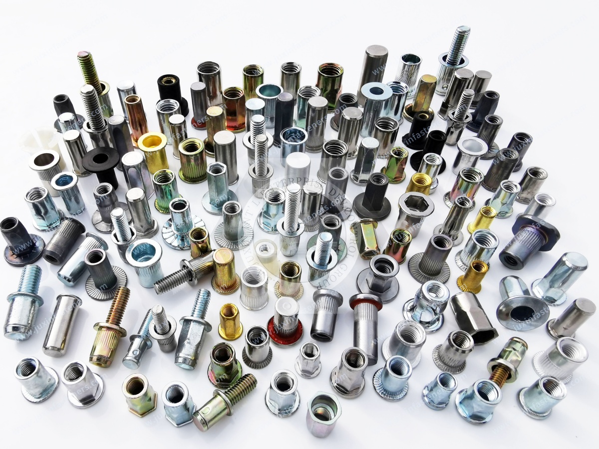
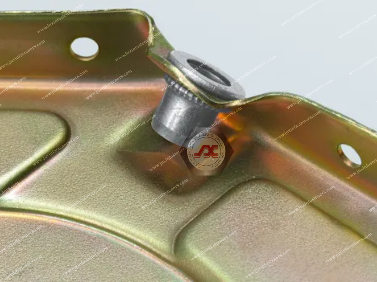
A blind rivet nut is an internally threaded fastener installed into a prepared hole from one accessible side of the workpiece.
During installation, a tool pulls on the internal thread while supporting the flange.
The deformable portion of the rivet nut collapses behind the substrate, creating a mechanical retention feature.
After the tool is removed, the rivet nut remains installed and provides an internal thread for a mating screw or bolt.
Main Functional Elements
A typical blind rivet nut includes:
Internal machine thread
Cylindrical or shaped body
Deformable setting section
Head or flange
Installation grip range
Defined overall length
Material and surface finish
Why Blind Installation Matters
Blind rivet nuts are particularly useful when the rear side of the substrate cannot be reached.
Examples include:
Closed box sections
Hollow metal profiles
Tubular structures
Electrical enclosures
Vehicle body panels
Preassembled equipment frames
Important Design Limitation
A blind rivet nut does not automatically provide the same strength as a welded nut, solid threaded block or through-bolt assembly.
Its performance depends on the complete rivet nut–substrate system.
How Do Blind Rivet Nuts Work?
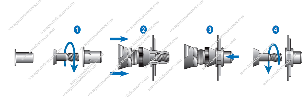
Blind rivet nuts create retention through controlled deformation of the insert body.
Installation Sequence
Prepare the specified installation hole.
Check the hole diameter, shape and burr condition.
Thread the rivet nut onto the installation tool mandrel.
Insert the rivet nut into the workpiece.
Support the flange against the substrate.
Apply the specified installation stroke or force.
Allow the deformable section to collapse behind the substrate.
Release the tool and check the installed condition.
The exact procedure depends on the rivet nut design and installation equipment.
What Happens During Setting?
The setting tool applies an axial force that compresses the deformable body section.
The body forms an enlarged region behind the substrate.
The flange and rear deformation provide retention.
Why Controlled Setting Is Essential
Insufficient setting can produce a loose insert.
Excessive setting may damage the internal thread, deform the flange or overload the substrate.
The correct setting parameters should be established using the actual rivet nut and workpiece.
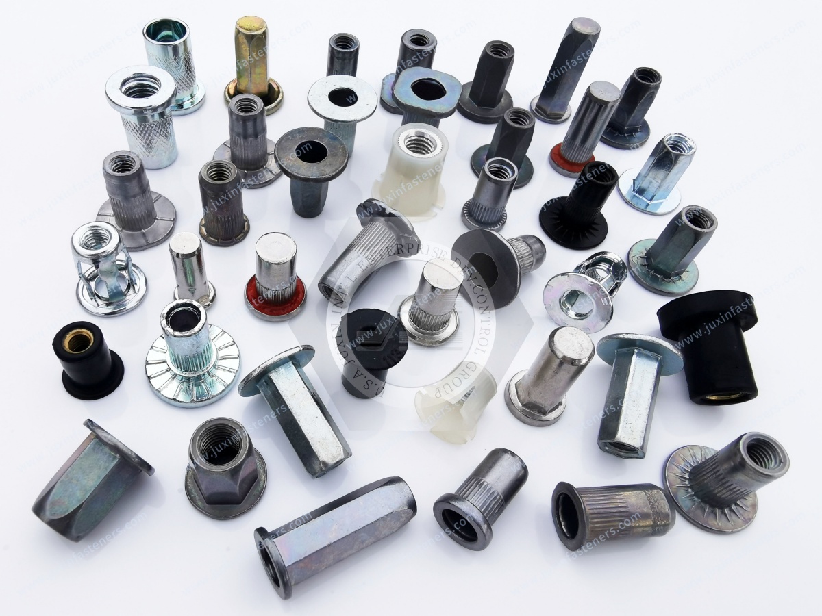
Types of Blind Rivet Nuts
Different rivet nut body designs provide different installation and retention characteristics.
The most suitable design depends on the substrate, hole preparation, loading and assembly process.
Round Body Rivet Nuts
Round body rivet nuts are widely used in general industrial sheet-metal applications.
Typical Applications
Electrical cabinets
Machinery covers
Industrial enclosures
Equipment frames
Sheet-metal housings
Advantages
Relatively simple hole preparation
Broad application suitability
Compatibility with many installation methods
Engineering Consideration
Round body designs may depend on body deformation, knurling or other retention features to resist rotation.
Their anti-rotation performance must be validated for the substrate and installation conditions.
Hex Body Rivet Nuts
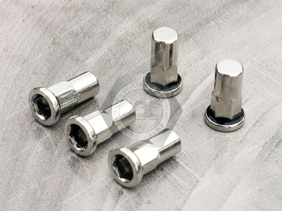
Hex rivet nuts have an external hexagonal body.
They are installed into a corresponding hexagonal hole.
Potential Advantages
Positive geometric resistance to rotation
Improved anti-rotation capability in suitable substrates
Useful for applications involving repeated screw installation
Design Considerations
The installation hole must match the specified hex geometry.
A round hole is not an acceptable substitute unless the particular product is designed and approved for it.
Applications
Automotive equipment brackets
Machinery assemblies
Sheet-metal structures
Industrial enclosures
Important Limitation
A hex body does not guarantee a particular spin-out torque.
Performance depends on the insert, hole tolerances, material and setting conditions.
Knurled Body Rivet Nuts
Knurled rivet nuts have external surface features intended to improve mechanical engagement with the substrate.
Potential Advantages
Additional anti-rotation engagement
Suitable for certain round-hole applications
Useful where the substrate can accommodate the knurl geometry
Applications
Aluminum panels
Industrial sheet metal
Selected plastic housings
Machinery covers
Engineering Consideration
Knurl effectiveness depends on the substrate hardness, thickness and installation process.
Knurled inserts are not automatically suitable for every plastic or composite material.
Slotted or Petal Rivet Nuts
Slotted rivet nuts are designed to form multiple expanded sections during installation.
The resulting petal-like deformation can distribute load over a larger rear contact area in suitable materials.
Potential Applications
Soft substrates
Selected plastics
Lightweight panels
Thin materials requiring broader rear support
Important Limitation
Petal-style expansion does not guarantee superior pull-out resistance in every substrate.
Performance must be tested with the actual panel material and thickness.
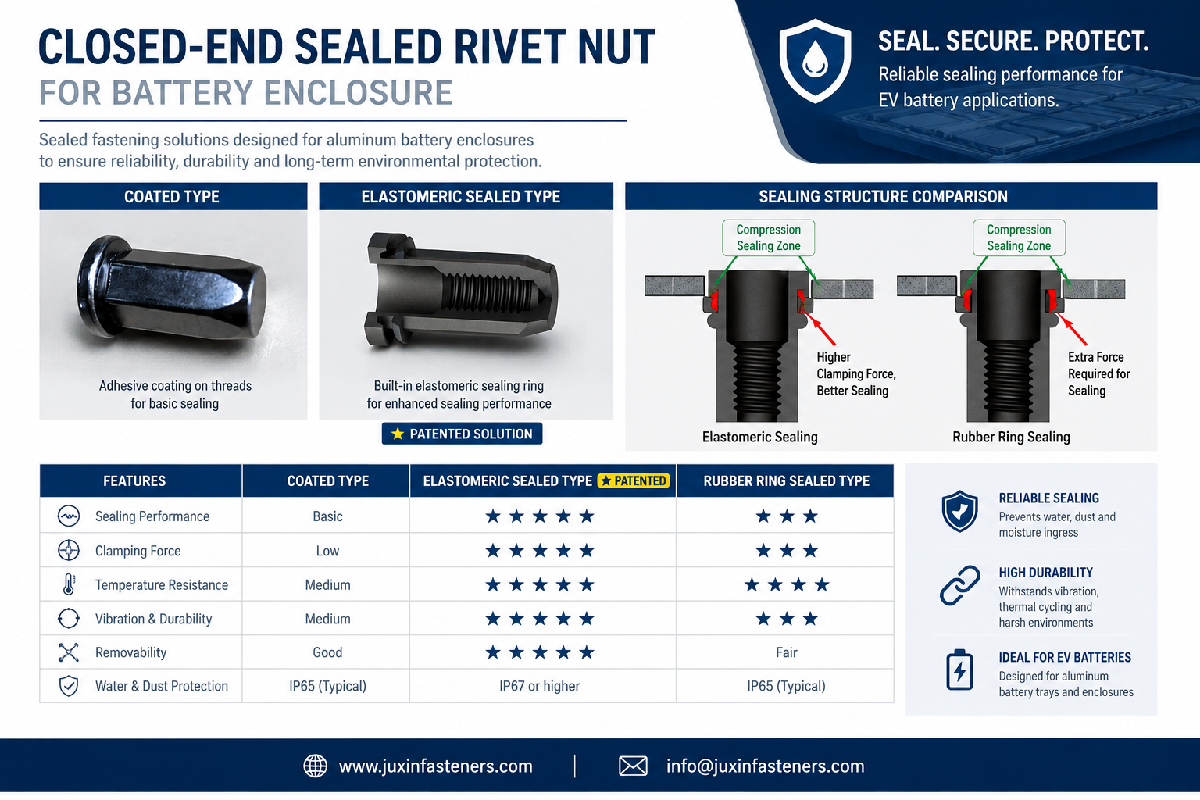
Sealed and Closed-End Rivet Nuts
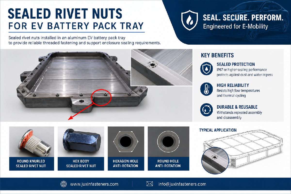
Sealed rivet nuts may use a closed-end body, sealing element or other design feature intended to limit fluid ingress.
Potential Applications
Outdoor electrical enclosures
Automotive electronics housings
Selected EV battery enclosure interfaces
Equipment exposed to moisture
Critical Sealing Principle
A closed-end rivet nut is not necessarily a complete waterproof joint.
Potential leakage paths include:
Flange-to-panel interface
Damaged or oversized installation holes
Incorrectly compressed sealing elements
Mating screw interfaces
Substrate distortion
IP67 and IP68 Claims
Ingress protection ratings under IEC 60529 apply to tested enclosure arrangements under specified conditions.
An individual sealed rivet nut should not be described as making an entire enclosure IP67 or IP68 without appropriate assembly-level validation.
Blind Rivet Nut Type Comparison
| Rivet nut type | Main design characteristic | Key consideration |
|---|---|---|
| Round body | Cylindrical outer profile | Hole size and anti-rotation performance |
| Hex body | Hexagonal outer profile | Correct hex hole geometry |
| Knurled body | External gripping features | Substrate engagement |
| Slotted/petal | Expanded rear sections | Rear-side load distribution |
| Closed-end | Closed body end | Sealing path and screw clearance |
| Sealed design | Dedicated sealing feature | Assembly-level leakage validation |
| Custom OEM | Drawing-specific geometry | Tooling and qualification |
Blind Rivet Nut Materials
Material selection influences strength, corrosion resistance, installation behavior, weight and cost.
Carbon Steel Rivet Nuts
Carbon steel rivet nuts are widely considered for general industrial applications.
Potential Advantages
Cost-effective material selection
Suitable mechanical performance
Availability of multiple protective finishes
Surface Treatment Options
Depending on the product and project requirements, possible finishes include:
Zinc plating
Zinc-nickel coating
Zinc-aluminum coating systems
Other approved finishes
Engineering Consideration
The selected coating must be compatible with the installation process and service environment.
Aluminum Rivet Nuts
Aluminum rivet nuts offer low weight and can be suitable for certain lightweight assemblies.
Potential Advantages
Reduced component weight
Suitable for selected aluminum structures
Relatively low installation force in some designs
Limitations
Lower mechanical strength than some steel alternatives
Potential thread wear
Galvanic corrosion concerns with dissimilar metals
Substrate-dependent pull-out and torque resistance
Stainless Steel Rivet Nuts
Stainless steel rivet nuts are considered where corrosion resistance is important.
Common material options include:
304 stainless steel
316 stainless steel
304 Stainless Steel
Often suitable for general industrial corrosion-resistant applications.
316 Stainless Steel
May offer improved resistance to certain chloride-containing environments because of its molybdenum content.
Important Limitations
316 stainless steel is not immune to pitting, crevice corrosion or stress corrosion cracking.
Stainless steel rivet nuts may require higher setting forces than softer alternatives.
Installation equipment must be suitable for the specified product.
Blind Rivet Nut Grip Range: How to Select the Correct Panel Thickness
Grip range is one of the most important specifications for a blind rivet nut.
It identifies the substrate thickness range for which the particular insert is designed to be installed.
Why Grip Range Matters
The deformable body must collapse correctly behind the substrate.
If the substrate is outside the intended grip range, the insert may not form the required retention geometry.
Too Thin a Substrate
Potential problems include:
Excessive rear deformation
Reduced stability
Panel distortion
Inconsistent retention
Too Thick a Substrate
Potential problems include:
Insufficient body collapse
Incomplete setting
Reduced pull-out resistance
Installation tool overload
How to Determine Grip Range
Measure the actual thickness of the substrate at the installation location.
Where multiple layers are involved, determine whether the rivet nut design is approved to clamp the full stack.
Consider:
Nominal sheet thickness
Material thickness tolerance
Coatings
Surface irregularities
Panel stack-up
Installation access
Engineering Example
A panel nominally specified at 2.0 mm may have a manufacturing thickness tolerance.
The selected rivet nut grip range must accommodate the permitted thickness variation.
The exact grip range must be taken from the approved product drawing or supplier specification.
Important Distinction
Grip range is not the same as maximum joint strength.
A rivet nut that fits the panel thickness still requires load validation.
Hole Size and Hole Geometry
The installation hole directly affects rivet nut performance.
Round Holes
Used for compatible round-body designs.
Hexagonal Holes
Used for compatible hex-body designs.
Hole Diameter or Across-Flats Dimension
Must follow the approved product specification.
Burr Control
Excessive burrs may prevent proper flange seating.
Hole Deformation
Poor punching or drilling quality may reduce retention consistency.
Edge Distance
The distance from the installation hole to the sheet edge must be sufficient for the substrate and loading.
Engineering Principle
A correct rivet nut installed into an incorrect hole may still fail.
Information Gain: Why Hole Tolerance Can Matter More Than Insert Strength
Consider two identical rivet nuts installed into panels of the same material and thickness.
Assembly A
The installation hole matches the specified size and shape.
Assembly B
The hole is oversized or distorted.
Even when the same installation tool setting is used, the assemblies may develop different anti-rotation and pull-out performance.
Potential Consequences
Insert rotation
Loose retention
Reduced load capacity
Assembly rework
Threaded joint failure
Design Lesson
Installation hole control is a functional requirement, not merely a manufacturing convenience.
Blind Rivet Nut Flange Design
The flange supports the rivet nut against the front surface of the substrate.
Flat Head or Large Flange Designs
May provide a larger bearing surface.
Reduced Head Designs
May reduce the amount the flange projects above the panel surface.
Countersunk Designs
May be selected where a flush installation is required, provided the substrate thickness and countersink geometry are suitable.
Engineering Considerations
Flange diameter
Flange thickness
Panel bearing stress
Countersink geometry
Component seating
Surface appearance
Important Limitation
A countersunk rivet nut should not be selected solely for appearance.
Removing material from a thin panel to create a countersink may reduce local substrate strength.
Pull-Out Resistance vs Spin-Out Torque
These are different performance characteristics.
Pull-Out Resistance
The axial load required to remove or fail the installed insert under a defined test condition.
Spin-Out Torque
The torque associated with rotation of the installed insert relative to the substrate under a defined test condition.
Why Both Matter
A rivet nut may resist axial loading but still rotate when a mating screw is tightened.
Conversely, a rivet nut may resist rotation but fail under excessive axial load.
Engineering Recommendation
Specify the appropriate mechanical tests according to the intended loading and assembly requirements.
Other Relevant Failure Modes
Thread stripping
Flange deformation
Substrate tearing
Fatigue damage
Insert fracture
Joint loosening
Installation Stroke and Installation Force
Rivet nut tools deform the insert using controlled mechanical action.
Stroke-Controlled Installation
The tool applies a defined displacement.
Force-Controlled Installation
The tool controls or monitors the applied setting force.
Why Tool Settings Matter
The correct setting depends on:
Rivet nut design
Material
Thread size
Grip range
Substrate thickness
Installation equipment
Under-Setting
May result in insufficient rear deformation.
Over-Setting
May damage the insert or substrate.
Production Recommendation
Validate the tool setting using actual production parts.
Do not assume one setting is suitable for all rivet nuts with the same thread size.
Blind Rivet Nut Installation Tools
Manual Installation Tools
Often suitable for maintenance, prototyping and low-volume work.
Pneumatic Installation Tools
May support faster production where compressed-air equipment is available.
Battery-Powered Installation Tools
Provide portability for suitable installation operations.
Electric and Automated Systems
May support process monitoring, repeatability and integration into production lines.
Production Manager's Considerations
Evaluate:
Installation cycle time
Tool ergonomics
Mandrel wear
Setup changes
Thread size changeover
Setting repeatability
Operator training
Maintenance
Inspection access
Important Qualification
A pneumatic or electric tool does not automatically produce correct installations.
The tool must be matched to the rivet nut and qualified setting parameters.
Blind Rivet Nuts for Automotive Manufacturing
Automotive assemblies may use blind rivet nuts where one-side access and reusable threaded attachment points are required.
Potential Applications
Interior brackets
Equipment covers
Selected body-mounted accessories
Wiring harness supports
Non-safety-critical sheet-metal assemblies
Engineering Considerations
Vibration
Substrate thickness
Corrosion exposure
Installation access
Assembly torque
Fatigue
Serviceability
Safety-Critical Applications
Seat mounts, restraint systems, suspension connections and other safety-critical structures require application-specific approval.
A general-purpose rivet nut must not be assumed suitable for these connections.
EV Battery Pack and Battery Enclosure Applications
EV battery assemblies may require threaded inserts for selected covers, brackets and accessory interfaces.
Potential Applications
Battery enclosure accessories
Electrical equipment mounting
Thermal management brackets
Service-access panels
Selected module support components
Engineering Considerations
Substrate material
Corrosion
Electrical isolation
Thermal expansion
Vibration
Sealing
Service requirements
Sealed Rivet Nuts in Battery Enclosures
A sealed rivet nut may contribute to an enclosure sealing strategy.
However, the complete assembly must be validated for the required environmental conditions.
Important Limitation
A rivet nut must not be selected for a safety-critical battery structural or electrical connection solely on the basis of its nominal material or thread size.
Rail Transit Applications
Blind rivet nuts may be used in selected rail equipment assemblies.
Potential Applications
Interior panels
Equipment cabinets
Electrical enclosures
Maintenance covers
Engineering Considerations
Vibration
Service access
Corrosion
Mechanical loading
Customer-specific qualification
Aerospace and Lightweight Structures
Blind threaded inserts may be considered for selected lightweight panels and interior equipment.
However, aerospace use requires appropriate product qualification, material control and customer approval.
Composite Materials
Composite substrates require particular attention to local crushing, delamination and load distribution.
A rivet nut designed for metal sheet should not automatically be used in composite material.
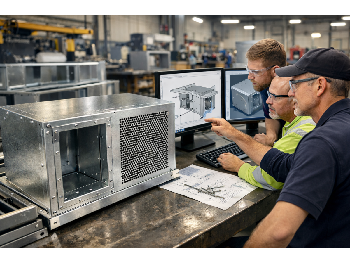
Electrical Cabinets and Sheet-Metal Fabrication
Electrical cabinets frequently use thin steel or aluminum panels.
Typical Applications
Control panels
Electrical enclosures
Equipment covers
Access doors
Cable management brackets
Why Rivet Nuts Are Useful
They provide internal threads where rear access is restricted.
Production Considerations
Hole punching consistency
Insert orientation
Tool access
Flange seating
Thread engagement
Repeated service removal
Alternative Fasteners
Depending on the design, engineers may also consider:
Self-clinching nuts
Weld nuts
Cage nuts
Clip nuts
Threaded inserts
Each alternative has different installation and load characteristics.
HVAC and Outdoor Equipment
HVAC equipment may use rivet nuts in sheet-metal housings and mechanical supports.
Potential Applications
Equipment covers
Service panels
Ventilation frames
Outdoor unit enclosures
Engineering Considerations
Moisture exposure
Corrosion
Thermal cycling
Vibration
Maintenance access
Material Selection
Carbon steel with an appropriate coating, aluminum or stainless steel may be considered depending on the environment and design.
Medical and Laboratory Equipment
Selected medical and laboratory equipment may use rivet nuts for removable covers and mechanical assemblies.
Potential Applications
Instrument housings
Laboratory equipment frames
Maintenance panels
Non-patient-contact mechanical components
Important Qualification
Material selection and installation performance must satisfy the applicable equipment requirements.
A stainless steel rivet nut is not automatically suitable for every medical application.
Machinery, Robotics and Automation
Industrial machinery often requires threaded mounting points in fabricated structures.
Potential Applications
Robotic equipment covers
Machine guarding accessories
Control cabinets
Sensor brackets
Automation frames
CNC machine enclosures
Production Benefits
Where properly designed, rivet nuts may simplify assembly and maintenance.
Design Limitations
High cyclic loads, severe vibration or critical structural loads may require alternative fastening methods.
Information Gain: Why Rivet Nut Rotation Occurs During Bolt Tightening
Rivet nut rotation is a common assembly problem.
Possible Causes
Oversized installation hole
Incorrect body style
Inadequate setting
Excessive tightening torque
Unsuitable substrate
Damaged knurling
Incorrect grip range
Engineering Solution
Review the installed insert and mating screw together.
A higher-strength bolt does not necessarily solve an insert rotation problem.
Information Gain: Why Pull-Out Failure Can Occur Below Expected Loads
An insert may fail through the substrate rather than through the rivet nut body.
Possible Causes
Thin panel
Weak substrate
Excessive edge loading
Incorrect hole geometry
Insufficient rear deformation
Bending loads
Poor load distribution
Engineering Lesson
The substrate is part of the load-bearing system.
Rivet nut strength cannot be evaluated independently of the panel.
Information Gain: Why Sealed Rivet Nuts May Still Leak
A closed-end rivet nut may prevent fluid from passing through the body end.
However, water may still enter through the flange-to-panel interface.
Possible Causes
Inadequate sealing element compression
Surface roughness
Panel distortion
Oversized hole
Damaged seal
Incorrect installation
Engineering Recommendation
Test the complete fastened assembly under the required environmental conditions.
Blind Rivet Nut Installation Quality Control
A reliable OEM assembly process requires appropriate controls.
Incoming Inspection
Check:
Product identity
Material
Thread size
Body dimensions
Flange dimensions
Surface condition
Grip range designation
Hole Inspection
Check:
Hole size
Hole shape
Burr condition
Edge distance
Substrate thickness
Installation Control
Check:
Tool compatibility
Setting parameters
Mandrel condition
Flange seating
Insert orientation
Post-Installation Verification
Depending on the application, verify:
Visual condition
Thread usability
Pull-out resistance
Spin-out torque
Assembly function
Sealing performance where required
Important Qualification
Inspection frequency and acceptance criteria must be defined by the approved quality plan.
Blind Rivet Nut Failure Mode Comparison
| Failure mode | Potential cause | Engineering action |
|---|---|---|
| Insert rotates | Hole or setting problem | Review anti-rotation design |
| Insert pulls out | Substrate or retention failure | Review grip range and loading |
| Thread strips | Excessive torque or insufficient engagement | Review thread and assembly requirements |
| Panel deforms | Excessive setting or weak substrate | Review setting and flange design |
| Flange does not seat | Burrs or incorrect hole | Improve hole preparation |
| Insert cracks | Material or installation issue | Review product and process |
| Corrosion occurs | Material or coating mismatch | Review environment and galvanic compatibility |
| Water leakage | Incomplete sealing interface | Validate complete assembly |
| Tool mandrel fails | Tooling or setting mismatch | Review equipment compatibility |
| Assembly misalignment | Hole location error | Review drawing datums and tolerances |
Blind Rivet Nuts vs Other Threaded Fastening Solutions
| Fastening method | Main advantage | Key limitation |
|---|---|---|
| Blind rivet nut | One-side installation | Requires correct grip and setting |
| Self-clinching nut | Compact sheet-metal thread | Requires suitable material and press access |
| Weld nut | Permanent welded attachment | Requires welding compatibility |
| Cage nut | Replaceable threaded element | Requires suitable mounting geometry |
| Clip nut | Convenient edge attachment | Depends on edge and panel design |
| Tapped hole | No separate insert | Limited thread engagement in thin sheet |
| Through-bolt and nut | Conventional joint arrangement | Requires access and assembly space |
How to Select the Right Blind Rivet Nut
A practical selection process should consider:
Substrate
Identify material, thickness and strength.
Access
Confirm whether installation is possible from one side.
Thread
Specify diameter, pitch and tolerance.
Grip Range
Select a product covering the actual thickness range.
Body Design
Choose round, hex, knurled, slotted or another suitable design.
Flange
Select the required head geometry.
Mechanical Loads
Define axial, torsional, bending and fatigue requirements.
Environment
Evaluate corrosion, temperature and moisture.
Sealing
Specify assembly-level leakage requirements where applicable.
Production
Confirm tool compatibility, installation rate and inspection requirements.
Commercial Requirements
Confirm production quantity, MOQ, delivery and packaging.
Metric and Inch Thread Compatibility
Blind rivet nuts may be manufactured with metric or Unified inch threads depending on the product design.
Metric Threads
Common nominal sizes include M3, M4, M5, M6, M8, M10 and M12, subject to the actual product range.
Metric thread requirements may reference applicable ISO thread standards.
Unified Inch Threads
UNC and UNF threads are separate systems commonly used in North American industrial applications.
The applicable ASME B1.1 requirements should be considered where specified.
Critical Compatibility Rule
Metric, UNC, UNF, BSW and BSF threads are not directly interchangeable.
Any inch-to-metric diameter conversion is dimensional reference only, not a thread compatibility statement.
OEM Supplier Qualification for Blind Rivet Nuts
Procurement teams should confirm more than the nominal thread size.
Product Requirements
Drawing and revision
Body style
Flange style
Material
Thread
Grip range
Surface treatment
Installation Requirements
Hole geometry
Tooling
Setting parameters
Substrate
Assembly loads
Quality Requirements
Dimensional inspection
Functional thread checks
Pull-out and spin-out requirements
Corrosion testing where specified
Sealing verification where applicable
Traceability requirements
Commercial Requirements
Prototype quantity
Annual demand
MOQ
Lead time
Packaging
Delivery schedule
Supplier Development Principle
Two rivet nuts with the same thread size may not be equivalent if their grip ranges, body designs, installation holes or retention performance differ.
OEM Blind Rivet Nut RFQ Checklist
| RFQ item | Required information |
|---|---|
| Product type | Round, hex, knurled, slotted, sealed or custom |
| Drawing | Drawing number and revision |
| Thread | Exact diameter and pitch |
| Thread system | Metric or specified inch system |
| Material | Carbon steel, aluminum, 304/316 stainless or specified grade |
| Body design | Outer diameter or hex geometry |
| Flange | Head type and dimensions |
| Grip range | Required substrate thickness range |
| Substrate | Material and thickness |
| Installation hole | Size, shape and tolerance |
| Installation tool | Equipment and setting method |
| Mechanical loads | Pull-out, spin-out and other relevant loads |
| Surface treatment | Coating or finish |
| Sealing | Required environmental performance |
| Inspection | Test methods and acceptance criteria |
| Packaging | Bulk or protected packaging |
| Prototype quantity | Sample demand |
| Annual demand | Expected production volume |
| MOQ | Commercial confirmation |
| Lead time | Required delivery schedule |
Frequently Asked Questions
What is the difference between a rivet nut and a nutsert?
Nutsert is a commonly used name for a blind threaded insert. Both terms are used in industrial sourcing, although exact product designs vary.
Can blind rivet nuts be installed from one side?
Yes. One-side installation is a defining feature of blind rivet nuts.
Are hex rivet nuts stronger than round rivet nuts?
Not necessarily in every loading condition. Hex designs may improve anti-rotation performance when installed in suitable hexagonal holes.
How do I select the correct grip range?
Measure the actual substrate thickness and choose an insert with an approved grip range covering that thickness.
Can rivet nuts be used in aluminum panels?
Yes, with suitable product selection and validation of installation and mechanical performance.
Are stainless steel rivet nuts corrosion-proof?
No. Stainless steel offers corrosion resistance but is not immune to corrosion in every environment.
Do sealed rivet nuts guarantee IP67 or IP68 protection?
No. The complete enclosure and fastened interface must be tested for the specified ingress protection requirement.
What causes a rivet nut to spin during bolt tightening?
Common causes include incorrect hole size, insufficient setting, unsuitable body design and excessive assembly torque.
Can blind rivet nuts replace weld nuts?
Sometimes. The alternative must meet the required load, installation, corrosion and production requirements.
What information should an OEM provide for a custom rivet nut quotation?
The drawing, thread, body design, material, grip range, substrate, hole geometry, performance requirements and expected production volume.
Juxin Fasteners: Blind Rivet Nuts and Custom OEM Threaded Inserts
Juxin Fasteners welcomes inquiries for standard and customized industrial threaded fastening products.
Relevant product categories include:
Blind rivet nuts
Round body rivet nuts
Hex body rivet nuts
Knurled rivet nuts
Slotted and petal rivet nuts
Sealed rivet nuts
Stainless steel rivet nuts
Aluminum rivet nuts
Carbon steel rivet nuts
Custom threaded inserts
Product availability, material grades, grip ranges, installation characteristics, manufacturing feasibility,
MOQ, inspection documentation and delivery schedules require confirmation against the customer's requirements.
Request Blind Rivet Nuts and OEM Quotations
Are you sourcing blind rivet nuts for sheet metal, hex rivet nuts, knurled rivet nuts, sealed rivet nuts or custom threaded inserts?
Juxin Fasteners welcomes inquiries from design engineers, mechanical engineers, manufacturing engineers, production managers,
procurement specialists, purchasing managers, supplier development teams and supply chain managers.
For technical review and quotation, please provide:
Product drawing and revision + thread designation + body type + flange design + material + surface finish + substrate material and thickness
+ grip range + installation hole + tool requirements + pull-out or spin-out performance + sealing requirements
+ inspection documentation + prototype quantity + annual demand + packaging + delivery schedule.
Company: Juxin Fasteners
Website: https://www.juxinfasteners.com/
Email: info@juxinfasteners.com
Send your blind rivet nut drawings and OEM RFQ to Juxin Fasteners for product selection, technical confirmation and quotation.
Contact Us
Tel.:
+86 020 8621 0320
+86 020 3121 6067
E-mail:
Technical Support:
Navigation
SEND INQUIREY



