Call Us
+86 136 6007 9809
Call Us
+86 136 6007 9809

Nov. 20, 2023
Thread failure is not always a fastener problem.
In many industrial assemblies, the bolt or screw is stronger than the material containing the internal thread.
Aluminum housings, magnesium components, castings and other lightweight materials can provide excellent weight and manufacturing advantages,
but their internal threads may become the limiting point when an assembly is exposed to repeated servicing, high clamp loads, vibration, thermal cycling or accidental over-torque.
Stainless steel wire thread inserts, also known as helical thread inserts, wire inserts, screw thread inserts and thread repair inserts, provide an engineered metal thread inside the parent material.
They can serve two very different purposes:
OEM thread reinforcement — designing the insert into a new component from the beginning to improve thread durability and serviceability.
Thread repair — restoring a stripped, worn or damaged internal thread while retaining the original nominal screw size where the repair design permits.
JUXIN FASTENERS supplies stainless steel wire thread inserts, free-running thread inserts, screw-locking thread inserts and customized threaded insert solutions for OEM manufacturers,
equipment builders, maintenance organizations and industrial supply chains.
Applications include automotive and EV equipment, industrial machinery, automation, electronics, railway equipment, transportation systems and other assemblies requiring durable reusable internal threads.
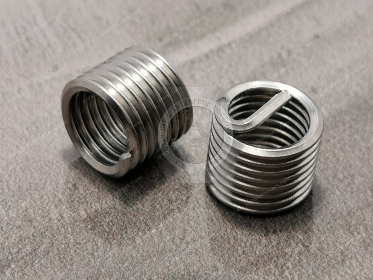
A wire thread insert is a helically formed insert manufactured from precision-profile wire.
The insert is installed into a specially prepared STI tapped hole—STI meaning Screw Thread Insert.
After installation, the insert provides an internal thread corresponding to the specified mating screw.
Instead of repeatedly tightening a steel screw directly into a softer parent material, the screw engages with the insert.
This changes the load-transfer interface from:
Steel Screw → Soft Parent Thread
to:
Steel Screw → Stainless Steel Insert → Parent Material
That difference can significantly improve thread durability in correctly engineered assemblies.
Wire thread inserts are commonly specified when an engineering team needs to:
reinforce threads in lower-strength parent materials;
improve durability under repeated assembly;
repair stripped or damaged threads;
retain the original nominal screw size after an approved repair;
reduce wear in frequently serviced threaded joints;
improve load distribution through the engaged thread;
provide a replaceable thread interface;
support lightweight material strategies without relying only on thicker bosses.
The important point is that a wire insert should not be viewed simply as a repair accessory.
In many OEM products, the insert is deliberately incorporated into the original component design.
These are two different commercial and engineering requirements.
An engineer may specify the insert during product development before any thread has failed.
Typical reasons include:
aluminum or magnesium parent material;
repeated maintenance cycles;
higher-strength mating screws;
critical service threads;
expected field disassembly;
reduced risk of stripping during production;
lightweight component design.
In this case, the insert is part of the original assembly specification.
A damaged tapped hole may otherwise require:
replacing an expensive housing;
machining the component;
increasing the thread size;
redesigning the mating fastener;
scrapping the assembly.
A properly engineered thread repair insert can restore the threaded location while often allowing the original nominal screw size to remain in use.
This can be particularly valuable for expensive castings, machinery housings, tooling and service components.
This is an important engineering distinction.
Installing a stainless steel wire thread insert does not mean every joint automatically becomes stronger.
Final thread performance depends on the complete system:
parent material;
parent-material strength;
insert length;
thread diameter;
installation-hole preparation;
STI thread quality;
insert material;
mating screw strength;
thread engagement;
installation quality;
operating temperature;
corrosion environment;
loading direction.
The insert provides a durable internal thread interface, but the load must still transfer from the insert into the surrounding parent material.
If the parent boss is too thin, edge distance is inadequate or the installation thread is incorrectly prepared, changing to a longer or stronger insert does not automatically solve the structural problem.
Aluminum is widely used for:
housings;
gearbox components;
electronic enclosures;
vehicle components;
automation equipment;
lightweight machinery;
transportation structures.
But repeated steel-screw installation directly into an aluminum thread can lead to wear or stripping depending on material grade, engagement and applied load.
A stainless steel wire thread insert for aluminum creates a durable internal thread while allowing the surrounding component to retain the weight and manufacturing advantages of aluminum.
This is especially valuable for service-access locations that may be opened and closed many times during the equipment lifecycle.
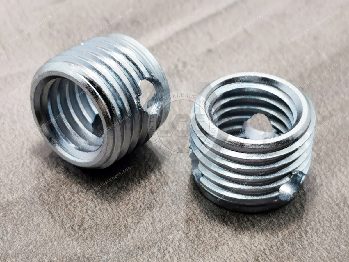
Magnesium alloys provide significant weight-saving opportunities but require careful threaded-joint design.
Wire inserts can be considered where designers require:
reusable metal threads;
controlled serviceability;
increased thread durability;
compatibility with higher-strength mating screws.
However, material compatibility and corrosion protection become particularly important when dissimilar metals are combined.
The correct solution must therefore consider the complete material system, not only the insert.
A free-running wire thread insert provides a standard internal thread without an intentional prevailing-torque locking feature.
It is commonly used for:
thread reinforcement;
thread repair;
frequently serviced assemblies;
aluminum housings;
machinery;
electronics;
industrial equipment.
Its primary function is to create a durable threaded interface.
A free-running insert should not automatically be described as a self-locking fastener.
If the joint requires resistance to screw loosening, the complete locking strategy must be considered.
A screw-locking wire thread insert incorporates one or more specially formed locking coils or locking features that create interference with the mating screw.
This produces a prevailing-torque effect.
Potential applications include:
vibration-sensitive equipment;
transportation systems;
industrial machinery;
railway equipment;
selected automotive assemblies;
equipment requiring controlled screw retention.
However, screw-locking inserts must be matched to:
mating screw material;
thread specification;
required prevailing torque;
service temperature;
assembly cycles;
lubrication condition.
A locking insert should therefore be specified as part of the joint design rather than treated as a universal anti-loosening solution.
| Engineering Requirement | Free-Running Insert | Screw-Locking Insert |
|---|---|---|
| Thread reinforcement | Excellent | Excellent |
| Damaged thread repair | Excellent | Application dependent |
| Normal screw installation | Yes | Prevailing torque present |
| Intentional screw locking | No | Yes |
| Frequent adjustment | Usually suitable | Evaluate torque retention |
| Vibration-sensitive joint | Requires separate locking evaluation | Can provide prevailing torque |
| Installation complexity | Standard | Additional specification required |
For procurement, always identify whether the drawing requires free-running or screw-locking inserts.
These products should not be treated as interchangeable.
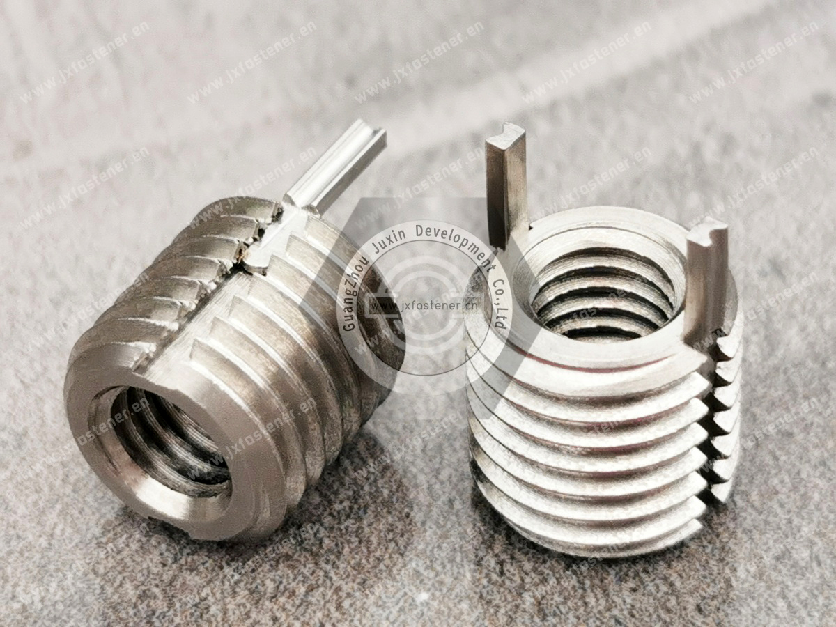
Traditional wire thread inserts may incorporate an installation tang.
The tang provides a drive feature used during insertion.
After installation, the tang may need to be removed depending on:
component design;
through-hole or blind-hole configuration;
project requirements;
risk of loose foreign material;
downstream assembly.
Tang removal should be planned as part of the manufacturing process rather than treated as an afterthought.
Tangless designs eliminate the conventional break-off tang and use alternative installation features.
They can be useful where manufacturers want to:
eliminate a tang-removal operation;
reduce loose-piece concerns;
automate installation;
simplify inspection after installation.
The choice between tanged and tangless wire thread inserts depends on installation equipment, production volume, component design and customer specification.
In high-volume production, specifying a tanged insert introduces more than an installation step.
The process may also require control of:
Tang Installed → Tang Broken → Tang Accounted For → Final Thread Inspected
If the assembly is sensitive to loose metallic debris, this process can become a significant quality-control consideration.
For this reason, OEM engineers should consider tang strategy during the design stage rather than waiting until production launch.
A wire thread insert is not installed into an ordinary tapped hole of the same nominal screw size.
The parent material requires a specially prepared thread for the insert.
The typical process is:
Prepare the installation hole.
Tap the hole using the specified STI tap.
Inspect the prepared STI thread where required.
Install the wire thread insert.
Position the insert at the specified depth.
Remove the tang when required.
Inspect the completed internal thread.
The final internal thread then accepts the intended mating screw.
This distinction is critical for engineering drawings and manufacturing instructions.
Machine or drill the installation hole according to the insert system specification.
Hole diameter and depth must provide sufficient material for the STI thread and the selected insert length.
Use the correct Screw Thread Insert tap for the specified insert.
Do not substitute a standard tap simply because the final mating screw has the same nominal thread size.
Where required by the quality plan, verify the STI tapped hole with the appropriate inspection method or gauge.
Install the wire insert using the appropriate manual, pneumatic or automated installation equipment.
During installation, the helical coil is wound into the STI thread and seats within the prepared parent thread.
The top coil should be positioned according to the specified installation requirement.
An insert installed too high can interfere with the mating component.
An insert installed too deep can reduce usable engagement or create assembly problems.
For tanged designs, remove the installation tang according to the application and process requirement.
Verify:
installation depth;
thread condition;
insert position;
tang removal where required;
mating screw engagement;
visual condition.
Wire thread inserts are commonly identified by length relative to nominal thread diameter.
For example:
1D = insert length approximately equal to one nominal thread diameter;
1.5D = approximately 1.5 times nominal diameter;
2D = approximately twice nominal diameter.
For an M6 thread, this means the nominal insert lengths correspond approximately to:
1D → 6 mm;
1.5D → 9 mm;
2D → 12 mm.
This provides engineers and buyers with a convenient way to specify engagement length.
No.
Increasing insert length can increase the amount of parent material involved in load transfer, but only while the surrounding structure can effectively support the load.
A 2D insert is not automatically better than a 1D insert.
Selection should consider:
parent material strength;
boss depth;
available hole depth;
mating screw strength;
required load;
edge distance;
assembly geometry;
cost and installation constraints.
The correct question is not:
“What is the longest insert available?”
It is:
“What insert length provides the required joint performance in this parent material?”
Hole geometry affects insert selection and installation planning.
A through hole generally provides more freedom for:
tap clearance;
tang handling;
screw projection.
A blind hole requires closer control of:
drilling depth;
STI tapping depth;
insert length;
installation depth;
bottom clearance;
mating screw length.
For blind holes, the engineer should ensure that the mating screw does not bottom before achieving the required clamp load.
Metric insert systems are commonly used with ISO metric screw threads.
When preparing a specification, identify:
nominal thread diameter;
thread pitch;
insert length;
free-running or locking design;
tanged or tangless configuration where applicable;
material;
applicable engineering specification.
Examples may include:
M3;
M4;
M5;
M6;
M8;
M10;
M12;
together with the required pitch and insert length.
Wire inserts are also available for Unified inch-thread systems used in North American and international equipment.
Specifications may involve:
UNC;
UNF;
other Unified thread requirements according to the engineering drawing.
The complete thread designation should be provided rather than requesting only a nominal diameter.
Depending on the project, wire thread insert assemblies may reference internationally recognized thread systems and customer-specific requirements.
Relevant specifications can include:
ISO metric screw thread requirements;
ASME/ANSI Unified inch thread requirements;
applicable aerospace or industrial insert specifications where specifically required by the customer;
customer drawings;
OEM engineering standards.
For critical applications, the governing drawing or project specification should define the required insert type, material, thread, length, locking function and inspection requirements.
JUXIN FASTENERS can review drawing-based requirements for OEM projects.
Stainless steel is widely used because it provides a useful combination of:
mechanical strength;
wear resistance;
corrosion resistance;
temperature capability;
manufacturing consistency.
Material selection should nevertheless be based on the actual service environment.
For special applications, alternative insert materials or surface treatments may be required.
A stainless steel insert installed into aluminum or magnesium creates a dissimilar-metal combination.
In dry indoor service, this may present little practical concern.
In the presence of:
moisture;
salt;
electrolytes;
condensation;
marine exposure;
galvanic corrosion must be considered.
Engineering controls may include:
suitable material selection;
coatings;
surface treatments;
isolation strategies;
sealants;
environmental protection.
The most corrosion-resistant insert material does not automatically create the most corrosion-resistant assembled joint.
When stainless steel mating screws engage stainless steel thread inserts, galling should be considered, particularly under:
high installation speed;
high tightening load;
repeated assembly;
dry threads;
incompatible surface conditions.
Depending on the application, engineers may evaluate:
approved lubricants;
suitable coatings;
mating material combinations;
controlled tightening speed;
appropriate torque specifications.
Lubrication can change torque-tension behavior, so it should be part of the controlled assembly specification rather than applied casually on production lines.
Wire thread insert selection for elevated or low-temperature applications should consider more than the insert material alone.
Evaluate:
insert alloy;
parent material;
mating screw;
differential thermal expansion;
operating temperature;
thermal cycling;
corrosion environment;
retained joint preload.
Special alloys may be required where conventional stainless steel does not meet the application requirement.
Potential automotive applications include:
aluminum housings;
drivetrain components;
electric motor housings;
electronics housings;
battery-system equipment;
serviceable brackets;
lightweight structural components.
The value of the insert is particularly clear where a component combines:
Lightweight Parent Material + Steel Fastener + Repeated Service
For EV applications, inserts can support lightweight component design while providing durable service threads.
Application-specific mechanical, corrosion and electrical requirements should still be validated by the vehicle or component engineering team.
Industrial equipment frequently contains high-value castings and machined housings.
Applications include:
CNC machinery;
pumps;
compressors;
hydraulic equipment;
pneumatic systems;
automation equipment;
industrial robots;
gearboxes;
production tooling.
Wire inserts can be specified during original manufacturing or used as part of an approved maintenance repair.
Automation systems frequently require repeated maintenance and replacement of:
sensors;
guards;
actuators;
brackets;
covers;
control components.
When these components attach to aluminum frames or housings, reinforced threads can improve service durability over the equipment lifecycle.
Lightweight metal housings are widely used in:
server infrastructure;
power electronics;
UPS equipment;
cooling equipment;
communication systems;
electrical enclosures;
control equipment;
precision instruments.
Wire thread inserts can provide durable threaded mounting points in aluminum housings that may be opened repeatedly for maintenance or component replacement.
For AI data-center hardware and power infrastructure, the primary benefit is not the word “AI”; it is the engineering requirement for reliable serviceable threads in high-value equipment.
Potential applications include:
equipment housings;
lighting assemblies;
HVAC equipment;
control systems;
passenger interior hardware;
maintenance-access components.
Where screw retention under vibration is required, engineers should distinguish between a standard free-running insert and a specified screw-locking insert.
The complete joint must still comply with the project-specific railway engineering requirements.
Lightweight alloys and highly controlled threaded joints make wire inserts relevant to aerospace and other high-reliability equipment.
However, aerospace applications frequently require tightly controlled:
material specifications;
insert standards;
traceability;
installation procedures;
approved suppliers;
inspection;
documentation.
Therefore, a general industrial wire insert should never be assumed to meet an aerospace requirement merely because its dimensions appear similar.
The exact customer drawing and applicable specification must be reviewed.
One of the strongest commercial use cases for wire thread inserts is avoiding unnecessary component replacement.
Consider an expensive machined aluminum housing containing one damaged M6 tapped hole.
Without an approved repair process, the manufacturer may face:
scrapping the housing;
machining to a larger thread;
modifying the mating component;
replacing the assembly.
A correctly engineered repair insert may restore the M6 internal thread while retaining compatibility with the original mating screw.
For MRO teams, this can reduce:
component replacement cost;
equipment downtime;
spare-part consumption;
redesign work.
The repair must still be appropriate for the component's engineering requirements.
Thread insert performance problems are often caused by installation or specification errors rather than the insert itself.
Using an incorrect drill or tap can prevent proper insert engagement.
An insert that is too short may not provide the required engagement.
An insert that is too long may interfere with the bottom of a blind hole or extend beyond the intended installation region.
Installing the top coil too close to or above the parent surface can interfere with assembly.
Misalignment can damage the insert or STI parent thread.
Improper tang breaking can damage the final coil or leave unwanted debris.
Wrong pitch, damaged threads or inappropriate screw geometry can damage the installed insert.
A reinforced thread is not an unlimited-strength thread.
The allowable assembly torque must remain compatible with the entire joint.
| Engineering Requirement | Selection Direction |
|---|---|
| General thread reinforcement | Free-running insert |
| Damaged thread repair | Free-running repair insert where approved |
| Intentional prevailing torque | Screw-locking insert |
| Repeated assembly | Evaluate free-running insert |
| Aluminum parent material | Stainless steel insert commonly considered |
| Magnesium parent material | Evaluate strength and galvanic protection |
| Blind hole | Verify depth, insert length and screw length |
| Through hole | Standard installation geometry often simpler |
| Loose tang unacceptable | Consider tangless design |
| Automated production | Evaluate installation-compatible insert design |
| Corrosive environment | Review complete material pairing |
| High temperature | Verify insert alloy and joint materials |
| High-vibration application | Evaluate locking insert and complete joint strategy |
A useful RFQ should provide more than:
“M6 stainless steel thread insert.”
For efficient technical review, specify:
internal thread size;
thread pitch;
metric or Unified thread system;
free-running or screw-locking;
tanged or tangless where required;
insert length: 1D, 1.5D, 2D or drawing dimension;
insert material;
parent material;
parent component thickness or boss depth;
blind or through hole;
operating temperature;
corrosion environment;
application;
required specification;
drawing;
annual quantity.
Need M6 stainless steel helicoil, 20,000 pcs.
Several engineering questions remain unanswered.
M6 × 1.0 stainless steel free-running wire thread insert, 1.5D length, tanged type, for aluminum equipment housing.
Blind-hole application with repeated service assembly. Please review drawing and quote 20,000 pcs initial requirement / 100,000 pcs annual usage.
The second RFQ allows engineering, purchasing and manufacturing teams to evaluate the same product requirement.
Depending on the drawing and customer specification, quality control may include:
Confirm the specified insert material according to project requirements.
Control relevant dimensions and wire-form characteristics according to the product specification.
Verify compatibility with the specified thread and STI installation system.
Sample installation into representative test pieces can help verify:
installation behavior;
insert positioning;
final thread condition;
mating screw engagement.
For screw-locking inserts, prevailing-torque requirements should be evaluated according to the applicable specification.
Inspect for:
damaged coils;
deformation;
surface defects;
contamination;
incorrect tang condition.
Before specifying a wire thread insert, answer these five questions:
1. Why is the insert required?
Thread reinforcement, repair, repeated service or screw locking?
2. What is the parent material?
Aluminum, magnesium, steel, composite or another material?
3. What engagement length is required?
1D, 1.5D, 2D or another length?
4. Is the hole blind or through?
This affects depth, installation and tang handling.
5. Does the application require free-running or prevailing torque?
Do not assume a standard insert provides screw locking.
Answering these questions early prevents many specification and sourcing problems.
JUXIN FASTENERS supports industrial customers requiring:
stainless steel wire thread inserts;
free-running helical inserts;
screw-locking wire inserts;
thread repair inserts;
metric thread inserts;
Unified inch thread inserts;
multiple insert lengths;
drawing-based threaded insert solutions;
OEM packaging and supply requirements.
For non-standard or critical applications, send the drawing and applicable technical specification for review.
This article should form part of the Threaded Inserts & Thread Reinforcement Content Cluster.
Recommended internal links:
Threaded Inserts Product Category
→ Main commercial product hub for threaded insert solutions.
Heat-Set Threaded Inserts for Plastics
→ Thread reinforcement for thermoplastic components.
Press-In Threaded Inserts
→ Mechanical inserts for suitable plastic and industrial assemblies.
Blind Rivet Nuts
→ Blind-installed threaded inserts for thin sheet metal.
Stainless Steel Fasteners
→ Corrosion-resistant screws, nuts and related fastening components.
Locking Fasteners
→ Solutions for assemblies requiring resistance to loosening.
Automotive Fastening Solutions
→ Threaded and mechanical fastening for vehicle assemblies.
Railway Fastening Solutions
→ Fastening systems for rail interiors and equipment.
Industrial Machinery Fasteners
→ Fastening solutions for automation, equipment and machinery.
Custom Fasteners According to Drawing
→ Commercial conversion page for OEM and non-standard projects.
The intended search-to-conversion path is:
Wire Thread Insert Search
→ Understand Reinforcement vs Repair
→ Select Free-Running or Locking
→ Define Thread Size
→ Select 1D / 1.5D / 2D Length
→ Review Parent Material
→ Define Tanged / Tangless Requirement
→ Submit Drawing & Specification
→ Technical Review
→ Sample / Quotation
→ OEM Supply
If you are sourcing stainless steel wire thread inserts, helical thread inserts, screw thread inserts, locking thread inserts or thread repair inserts, send JUXIN FASTENERS your technical requirements.
For faster quotation and engineering review, provide:
Thread Size + Pitch + Insert Length + Free-Running/Locking + Tanged/Tangless + Parent Material + Blind/Through Hole + Application + Standard/Drawing + Quantity
For damaged-thread repair projects, also provide the original thread specification and component material.
For OEM projects, providing the component drawing helps our team evaluate the insert requirement within the complete assembly rather than selecting the insert by nominal thread size alone.
JUXIN FASTENERS
Website: www.juxinfasteners.com
Email: info@juxinfasteners.com
Contact Us
Tel.:
+86 020 8621 0320
+86 020 3121 6067
E-mail:
Technical Support:
Navigation
SEND INQUIREY