Call Us
+86 136 6007 9809
Call Us
+86 136 6007 9809

Nov. 20, 2023
Why would an engineer install a stainless steel insert into a perfectly good threaded hole?
The answer is not simply “to make the thread stronger.”
A wire thread insert, also called a helical thread insert, screw thread insert, wire insert or thread reinforcement insert,
changes the way a threaded joint transfers load between the mating screw and the parent component.
In lightweight materials such as aluminum and magnesium alloys, the mating screw may be significantly stronger than the internal thread formed directly in the parent material.
Repeated assembly, excessive tightening, vibration, thermal cycling or insufficient thread engagement can eventually damage the parent thread.
A properly specified stainless steel wire thread insert creates a durable metal thread interface between the screw and the parent material.
For OEM engineers, this can improve thread durability and serviceability.
For maintenance teams, a related insert system can also restore damaged internal threads without automatically requiring replacement of an expensive component.
JUXIN FASTENERS supplies stainless steel wire thread inserts, free-running thread inserts, screw-locking thread inserts and thread repair solutions for industrial OEM applications.
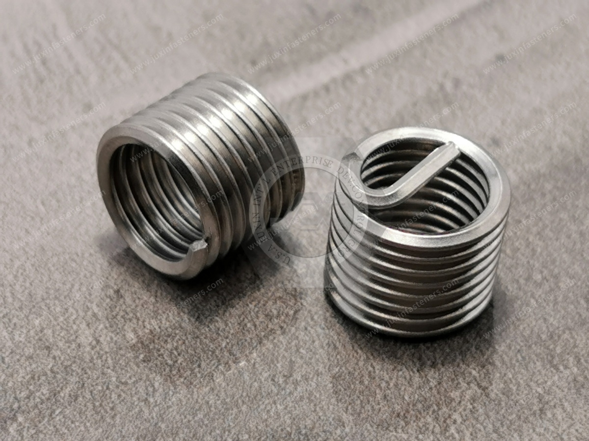
A wire thread insert can perform several engineering functions depending on how the joint is designed.
The primary functions are:
Reinforce internal threads in lower-strength materials
Reduce wear from repeated screw installation
Improve load transfer through the threaded engagement
Protect expensive parent components from thread damage
Restore stripped or damaged threads
Provide prevailing torque when a screw-locking insert is specifically selected
These functions should not be treated as interchangeable.
For example, a standard free-running insert reinforces the thread but does not automatically function as a locking fastener.
Threaded-joint failure is often discussed as if the bolt itself were the only critical component.
In reality, an internally threaded joint contains several interacting elements:
Mating Screw
↓
Internal Thread
↓
Parent Material
↓
Component Geometry
If the screw is made from a relatively strong steel while the internal thread is machined directly into a lower-strength aluminum alloy, the parent thread can become the weak link.
Possible failure modes include:
thread stripping;
progressive thread wear;
deformation;
local shear failure;
cross-threading damage;
damage from excessive installation torque;
deterioration after repeated maintenance cycles.
The purpose of the insert is to provide a more durable threaded interface while transferring load into the surrounding parent material.
A stainless steel wire thread insert is formed from precision-profile wire into a helical configuration.
The parent component is prepared with a special STI thread—STI meaning Screw Thread Insert.
The insert is then installed into this prepared thread.
Once installed, the assembly becomes:
Screw → Wire Thread Insert → STI Parent Thread → Component
instead of:
Screw → Parent Material
This architecture separates the reusable screw-engagement surface from the softer parent material.
That is the fundamental engineering purpose of the insert.
It can significantly improve the performance of a threaded connection in suitable parent materials, but the answer requires an important qualification:
The insert does not make the surrounding component infinitely strong.
Final joint performance depends on:
parent material strength;
insert length;
nominal thread diameter;
STI thread quality;
boss diameter;
edge distance;
wall thickness;
mating screw strength;
engagement length;
loading direction;
installation quality.
The load still has to transfer from the insert into the parent component.
This means the correct engineering question is not:
“Is a helical insert stronger?”
It is:
“Does this insert configuration provide sufficient thread performance in this parent material and geometry?”
Thread load is not distributed perfectly equally across every engaged thread.
In a conventional threaded joint, the first engaged threads typically carry a greater proportion of the load than threads farther along the engagement.
This creates localized stress concentration.
A properly designed insert system can provide a more resilient interface between the mating screw and parent material and can help improve load distribution through the engaged thread system.
This is one reason wire inserts are valuable in components where direct threading into relatively soft material would otherwise limit joint durability.
However, load distribution still depends on:
insert design;
parent material;
engagement length;
screw stiffness;
geometry;
preload.
It should therefore be evaluated as a complete joint rather than as an isolated insert specification.
Aluminum provides important engineering advantages:
low density;
good machinability;
corrosion resistance;
thermal performance;
weight reduction.
It is therefore widely used in:
automotive housings;
EV equipment;
electronics;
industrial automation;
machinery;
transportation equipment;
precision instruments.
But the threaded hole can become a service-life limitation when steel screws are repeatedly installed and removed.
A stainless steel wire thread insert for aluminum creates a durable reusable internal thread while allowing the main component to remain lightweight.
This makes inserts particularly useful where engineers want both:
Lightweight Component + Durable Service Thread
Wire inserts should not be viewed only as repair components.
They may be designed into an OEM component from the beginning.
Consider an insert during product development when one or more of the following conditions exist:
the parent material is relatively soft;
the threaded location will be serviced repeatedly;
the mating screw has significantly higher strength than the parent material;
thread stripping would damage an expensive component;
the assembly requires reliable field maintenance;
component weight must remain low;
the thread is located in a critical service area;
replacement of the parent component would be costly.
This changes the insert from a repair accessory into a design-for-serviceability component.
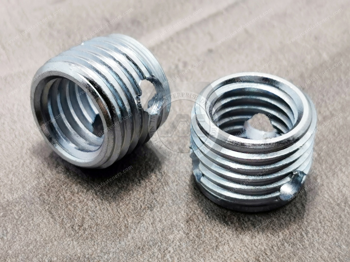
A thread insert may cost more than creating a basic tapped hole.
But procurement cost should not be evaluated only at the individual fastener level.
Consider two designs:
Initial machining cost may be lower.
If the thread is damaged during production or field maintenance, the entire housing may require repair or replacement.
Initial component cost includes the insert and installation process.
However, the thread interface is specifically designed for repeated service.
For high-value components, engineers and procurement teams should therefore consider:
Thread Cost + Assembly Cost + Failure Risk + Maintenance Cost + Component Replacement Cost
rather than comparing only the purchase price of the insert.
These are related but different applications.
The insert is installed into a correctly prepared new component.
Purpose:
improve thread durability;
support repeated assembly;
protect softer parent material;
improve serviceability.
The original internal thread has already been stripped, worn or damaged.
A repair process prepares the damaged location for the insert system so that the original nominal mating screw can often continue to be used where the approved repair design permits.
Purpose:
recover the component;
avoid unnecessary replacement;
retain mating-part compatibility;
reduce equipment downtime.
For OEM manufacturing, reinforcement is preventive.
For MRO operations, thread repair is corrective.
Consider an aluminum industrial gearbox housing with one damaged threaded mounting hole.
Replacing the complete housing may involve:
purchasing a new casting;
machining;
disassembly;
reassembly;
alignment;
production downtime.
If an approved thread repair insert can restore the original nominal thread, the repair may preserve the expensive parent component.
Typical repair applications include:
aluminum housings;
engine components;
machine tools;
industrial equipment;
tooling;
automation equipment;
pumps and compressors;
maintenance equipment.
The suitability of any repair must still be evaluated against the component's engineering requirements.
A free-running wire thread insert creates a durable standard internal thread.
Its primary functions are:
thread reinforcement;
wear resistance;
repeated assembly;
thread repair;
protection of the parent material.
Typical applications include:
aluminum housings;
industrial machinery;
electronic equipment;
automation;
automotive components;
precision equipment.
A free-running insert should not be marketed as inherently self-locking.
If screw retention under vibration is required, the joint needs a separate locking strategy or a specified locking insert.
A screw-locking helical insert incorporates specially formed locking coils that interact with the mating screw to create prevailing torque.
This can be useful in vibration-sensitive assemblies.
Applications may include:
transportation equipment;
railway systems;
industrial machinery;
automotive equipment;
automation;
selected high-performance assemblies.
The locking function must be matched to:
screw specification;
required prevailing torque;
service temperature;
lubrication;
assembly cycles;
applicable technical specification.
| Requirement | Free-Running | Screw-Locking |
|---|---|---|
| Reinforce parent thread | Yes | Yes |
| Repair damaged thread | Common | Application dependent |
| Normal screw rotation | Yes | Prevailing torque present |
| Intentional locking function | No | Yes |
| Frequent servicing | Often suitable | Evaluate torque requirements |
| Vibration-sensitive joint | Requires locking strategy | Locking feature available |
This distinction is important for both engineering drawings and procurement RFQs.
Repeated screw installation can progressively wear a parent thread.
Risk increases when:
the parent material is soft;
assembly torque is high;
the screw is harder than the parent material;
installation alignment varies;
maintenance is frequent;
power tools are used;
contamination enters the thread.
The insert becomes the sacrificial and replaceable threaded interface between the mating screw and expensive component.
This is particularly useful for covers, access panels, sensors and service components that may be removed repeatedly during equipment life.
They can provide a more durable thread interface, but they do not eliminate incorrect assembly.
Cross-threading can still occur if:
the screw enters at an angle;
the wrong thread pitch is used;
threads are damaged;
automated installation alignment is incorrect;
excessive force is applied.
Production processes should therefore control screw alignment and thread compatibility regardless of whether an insert is present.
No insert should be treated as protection against unlimited tightening torque.
The complete joint has a finite load capacity.
Excessive torque can potentially damage:
the mating screw;
the insert;
the parent material;
the clamped component.
Specified tightening procedures must therefore remain compatible with the joint design.
Wire inserts are commonly specified by length relative to nominal thread diameter.
Common designations include:
1D
1.5D
2D
For example, an M8 × 1.25 insert specified as 1.5D has a nominal installed insert length based on approximately 1.5 times the nominal thread diameter.
Longer engagement can involve more parent material in load transfer, but:
Longer does not automatically mean better.
Selection depends on:
parent material;
available boss depth;
load;
screw strength;
edge distance;
blind-hole depth;
component geometry.
A common sourcing assumption is:
“If 1D works, 2D must be stronger.”
This is too simplistic.
If the surrounding parent material or component geometry becomes the limiting failure mode, increasing insert length may provide little additional practical benefit.
A longer insert may also:
require deeper drilling;
require deeper STI tapping;
increase installation time;
create blind-hole clearance problems;
increase cost.
The correct length should therefore be selected from the joint requirement rather than by maximizing insert length.
Stainless steel provides excellent corrosion resistance in many environments.
However, engineers must also consider the parent material.
Installing stainless steel into aluminum or magnesium creates a dissimilar-metal interface.
Where moisture or another electrolyte is present, galvanic corrosion may become an engineering consideration.
Evaluate:
service environment;
humidity;
salt exposure;
coatings;
surface treatments;
isolation;
sealants;
drainage;
maintenance conditions.
Selecting a corrosion-resistant insert alone does not guarantee corrosion resistance of the complete assembly.
Where stainless steel mating screws engage stainless steel inserts, thread galling may become relevant.
Risk can increase with:
high tightening speed;
high preload;
repeated assembly;
dry threads;
incompatible surface conditions.
Depending on the project, engineers may evaluate suitable:
lubrication;
coatings;
mating materials;
tightening speed;
installation procedures.
Any lubricant must be considered in the torque-preload specification because lubrication changes friction.
Temperature changes can affect:
parent material expansion;
insert expansion;
screw expansion;
preload;
corrosion behavior.
This is particularly important when stainless steel inserts are installed in aluminum components because the materials have different thermal expansion characteristics.
Applications involving repeated heating and cooling should therefore be evaluated as a complete material system.
Potential applications include:
aluminum motor housings;
transmission housings;
power electronics;
battery-system components;
serviceable brackets;
lightweight equipment structures;
sensor mounting locations.
Wire inserts are particularly valuable where the assembly combines:
Lightweight Material + Higher-Strength Screw + Repeated Service
Industrial machinery frequently contains expensive machined components.
Applications include:
CNC equipment;
hydraulic systems;
pneumatic equipment;
pumps;
compressors;
gearboxes;
automation machinery;
production tooling.
Reinforcing frequently serviced threads can help protect the parent component during its operating lifecycle.
Automation equipment frequently requires maintenance of:
sensors;
actuators;
brackets;
guards;
covers;
control equipment.
When these parts attach to aluminum frames or housings, thread inserts can provide more durable service threads.
Aluminum housings and lightweight structural components are widely used in:
server hardware;
power electronics;
UPS systems;
cooling equipment;
control systems;
network infrastructure;
communication equipment.
The engineering value of the insert is straightforward:
reliable reusable threads in lightweight, high-value equipment.
For service-access locations, reinforced threads can reduce wear during repeated maintenance cycles.
Railway equipment may use reinforced threaded connections in:
passenger interior equipment;
lighting assemblies;
HVAC equipment;
electronic housings;
control equipment;
service panels.
Where vibration resistance is required, engineers should determine whether the joint requires:
a free-running insert plus another locking method; or
a specified screw-locking insert.
The insert selection should be coordinated with project-specific railway requirements.
Aerospace is one of the best-known applications for lightweight material thread reinforcement.
However, aerospace components may require specific:
insert standards;
approved materials;
installation procedures;
traceability;
inspection requirements;
supplier approvals.
A general industrial insert should never be assumed to satisfy an aerospace specification based only on thread size.
The governing drawing and technical specification must be reviewed.
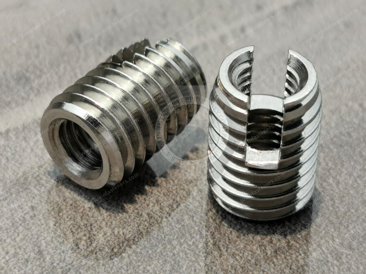
Depending on the project, relevant specifications may include:
DIN 8140 wire thread insert requirements;
ISO metric thread requirements;
ASME/ANSI Unified thread requirements;
UNC thread series;
UNF thread series;
UNEF thread series;
applicable aerospace insert specifications;
OEM drawings and engineering standards.
For critical applications, the customer drawing should define the governing requirements.
JUXIN FASTENERS can review standard and drawing-based insert requirements for OEM projects.
A typical tanged wire thread insert installation involves:
Drill or machine the hole according to the specified insert system.
Use the correct STI tap.
The STI thread is not the same as an ordinary tapped hole for the final mating screw.
Where required, verify the prepared STI thread before installation.
Use the appropriate manual, pneumatic or automated installation equipment.
Ensure that the top coil is positioned according to the installation specification.
For tanged inserts, remove the installation tang where required.
Check:
insert position;
internal thread condition;
installation depth;
tang condition;
mating screw engagement.
Wire inserts are useful, but they are not the correct solution for every threaded joint.
An engineer should first evaluate whether:
the parent material already provides sufficient thread strength;
the assembly is never serviced;
the component geometry supports the required load;
another insert technology is more suitable;
blind installation is required;
sealing is required;
installation cost outweighs the lifecycle benefit.
For example:
Thin Sheet Metal
A blind rivet nut may be more appropriate because there may not be enough material for an STI tapped hole.
Thermoplastic Components
Heat-set, ultrasonic or molded-in threaded inserts may be more appropriate depending on the plastic and production method.
Blind Sheet-Metal Assembly
A blind rivet nut can provide a threaded connection where backside access is unavailable.
This is why threaded insert selection should begin with the parent material and assembly architecture, not the insert catalog.
| Feature | Wire Thread Insert | Blind Rivet Nut |
|---|---|---|
| Typical parent material | Machined/cast material | Thin sheet/tube |
| Parent thread preparation | STI tapped hole | Installation hole |
| Primary purpose | Reinforce/repair threads | Create blind thread |
| Thin sheet application | Usually not primary choice | Excellent |
| Thread repair | Excellent use case | Not primary purpose |
| One-side installation into sheet | Not equivalent | Yes |
| Aluminum housing reinforcement | Excellent | Application dependent |
This comparison helps engineers avoid selecting products only because both are called “threaded inserts.”
Solid threaded inserts and wire thread inserts solve overlapping but different engineering problems.
Wire inserts offer:
low installed mass;
compact design;
excellent thread reinforcement;
established repair capability.
Solid inserts may be preferred where the application requires:
a solid-wall insert geometry;
different installation retention;
specific pull-out behavior;
special parent materials;
application-specific sealing or positioning.
The correct insert should be selected according to the joint requirement rather than by product familiarity.
Before specifying a wire thread insert, define:
Parent Material
Aluminum, magnesium, steel or another material?
Thread System
Metric, UNC, UNF, UNEF or another specified thread?
Thread Size and Pitch
What screw must the finished thread accept?
Insert Function
Reinforcement, repair or locking?
Insert Length
1D, 1.5D, 2D or drawing-defined length?
Hole Type
Blind or through?
Insert Style
Free-running or screw-locking?
Installation Style
Tanged or tangless if applicable?
Environment
Temperature, moisture, chemicals, salt exposure?
Service Frequency
How often will the screw be removed?
Applicable Standard
DIN, ISO, ASME/ANSI, aerospace specification or OEM drawing?
Procurement teams can accelerate technical review by providing:
thread size;
thread pitch;
metric or inch system;
insert length;
free-running or locking;
tanged or tangless requirement;
insert material;
parent material;
blind or through hole;
operating environment;
applicable standard;
drawing;
prototype quantity;
production quantity;
annual demand.
Instead of requesting:
“M6 stainless steel thread insert.”
A better RFQ is:
“M6 × 1.0 stainless steel free-running wire thread insert, 1.5D, tanged, for an aluminum equipment housing,
blind-hole application, 50,000 pcs annual requirement. Drawing attached.”
That gives engineering, quality and procurement teams enough information to evaluate the requirement efficiently.
Depending on the customer specification, wire thread insert quality control may include:
material verification;
dimensional inspection;
thread compatibility;
wire-form inspection;
surface condition;
installation testing;
mating screw verification;
insert positioning;
locking performance for screw-locking designs.
For OEM supply, inspection requirements should be defined according to the drawing and application rather than relying only on nominal thread size.
For industrial OEM sourcing, unit price is only one consideration.
Procurement and supplier-development teams should evaluate whether the supplier can understand and control:
thread specifications;
insert length;
insert type;
locking requirements;
material requirements;
drawing revisions;
inspection criteria;
packaging;
lot traceability requirements;
sample approval;
production consistency.
The objective is not simply to purchase a coil of stainless steel wire.
It is to source a repeatable threaded-interface component that matches the engineering specification.
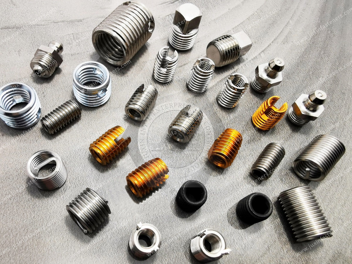
JUXIN FASTENERS supports industrial OEM customers requiring:
stainless steel wire thread inserts;
helical thread inserts;
free-running thread inserts;
screw-locking thread inserts;
thread reinforcement inserts;
thread repair inserts;
metric wire thread inserts;
Unified inch thread inserts;
drawing-based threaded insert solutions.
Applications include automotive and EV equipment, railway equipment, electronics, automation, industrial machinery and other engineered assemblies.
For special or critical applications, customers should provide the governing drawing and technical specification for review.
This article should support—not compete with—the main Wire Thread Insert Selection & Thread Repair Guide.
Recommended internal links:
Stainless Steel Wire Thread Insert Selection Guide
→ Detailed selection of free-running vs locking, 1D/1.5D/2D, STI holes and installation.
Threaded Inserts Product Category
→ Main commercial threaded insert product hub.
Blind Rivet Nuts
→ Thread creation in thin sheet metal and hollow structures.
Closed-End Rivet Nuts
→ Blind threaded connections where environmental protection is required.
Heat-Set Threaded Inserts for Plastics
→ Thread reinforcement for thermoplastic components.
Stainless Steel Fasteners
→ Related corrosion-resistant fastening components.
Automotive Fastening Solutions
→ OEM fastening for vehicle and EV assemblies.
Railway Fastening Solutions
→ Fastening systems for railway interiors and equipment.
Industrial Machinery Fasteners
→ Fastening solutions for machinery, automation and equipment.
Custom Fasteners According to Drawing
→ RFQ conversion page for engineered OEM requirements.
The intended visitor journey is:
Why Use a Thread Insert?
→ Identify Parent Material
→ Determine Reinforcement or Repair
→ Free-Running or Locking
→ Select Thread & Insert Length
→ Review Operating Environment
→ Compare Insert Technologies
→ Send Drawing / Specification
→ Engineering Review
→ Sample / Quotation
→ Production Supply
If you are evaluating wire thread inserts for aluminum, stainless steel helical inserts, thread reinforcement inserts, screw-locking inserts or thread repair inserts,
send JUXIN FASTENERS your application requirements.
For efficient engineering review and quotation, provide:
Thread Size + Pitch + Insert Length + Free-Running/Locking + Parent Material + Blind/Through Hole + Operating Environment + Standard/Drawing + Quantity
For OEM projects, the component drawing is particularly useful because thread-insert performance depends on the complete parent-material and joint design—not only the nominal screw size.
JUXIN FASTENERS
Email: info@juxinfasteners.com
Website: www.juxinfasteners.com
Contact Us
Tel.:
+86 020 8621 0320
+86 020 3121 6067
E-mail:
Technical Support:
Navigation
SEND INQUIREY