Call Us
+86 136 6007 9809
Call Us
+86 136 6007 9809

Nov. 22, 2023
Self tapping threaded inserts are available in multiple geometries because no single insert design is ideal for every parent material, wall thickness, installation condition, or mechanical load.
For design engineers and sourcing teams, the important question is therefore not simply:
“Do I need a self tapping insert?”
The more useful question is:
“Which self tapping insert geometry best matches the parent material, available installation space, required internal thread, installation process, and mechanical load?”
Common industrial configurations include slotted self tapping inserts, cutting-hole inserts, thin-wall inserts, flanged inserts, and specialized designs for particular installation conditions.
Product families may also be identified by series designations such as 302, 302H, 303, 307, 308, 307H, 308H, 317, 318, 337 and 338, depending on the applicable product system and supplier.
JUXIN FASTENERS supplies self tapping threaded inserts and drawing-based threaded insert solutions for suitable aluminum alloys, engineering plastics,
cast components, non-ferrous materials, machinery, automotive components, electrical equipment, automation systems, transportation equipment, and industrial OEM assemblies.
This engineering guide explains how to compare self tapping insert types by geometry and application rather than selecting an insert from nominal thread size alone.
A practical selection process begins with:
Parent Material → Available Wall Thickness → Internal Thread → Insert Outside Diameter → Cutting Geometry → Flange Requirement → Pilot Hole → Installation Torque → Pull-Out / Torque-Out Requirement
Typical engineering considerations include:
General-purpose slotted geometry: evaluate 302-style inserts.
Limited radial installation space: evaluate thin-wall configurations such as 303-style inserts where technically suitable.
Different cutting requirements or parent-material behavior: evaluate cutting-hole geometries such as 307/308-style inserts.
Need for a positive seating surface or flange-related load distribution: evaluate H/flanged configurations.
Blind-hole or contamination-sensitive assembly: evaluate insert geometry specifically designed for the required hole and chip-management condition.
These are selection directions, not universal interchangeability rules.
Series designations should always be confirmed against the actual insert drawing.
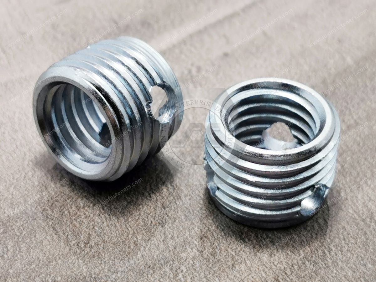
A self tapping threaded insert is a solid insert containing an internal machine thread and an external geometry designed to establish its own engagement in a correctly prepared receiving hole.
Depending on design, the insert may use:
cutting slots;
cutting holes;
external cutting threads;
tapered lead geometry;
flanges;
specialized external profiles.
Unlike insert technologies that require a specially pre-tapped receiving thread, self tapping inserts are normally installed directly into a controlled pilot hole.
After installation, the internal thread provides the fastening interface for the mating screw.
Common search terminology includes:
self tapping inserts;
self tapping threaded inserts;
self tapping screw inserts;
self tapping screw sleeves;
solid threaded inserts;
tapping inserts;
threaded inserts for aluminum;
threaded inserts for plastic;
thread reinforcement inserts.
Because these terms overlap, engineers should use dimensions and geometry—not terminology alone—when qualifying a part.
The external geometry determines how the insert interacts with the parent material during installation and service.
Different designs can change:
cutting behavior;
chip formation;
installation torque;
radial stress;
required pilot-hole diameter;
available wall thickness;
pull-out behavior;
torque-out behavior;
installed position;
required component space.
This means two inserts with the same M6 internal thread can require very different:
pilot holes;
outside diameters;
boss dimensions;
installation tools;
assembly parameters.
Nominal thread size alone is therefore insufficient for insert selection.
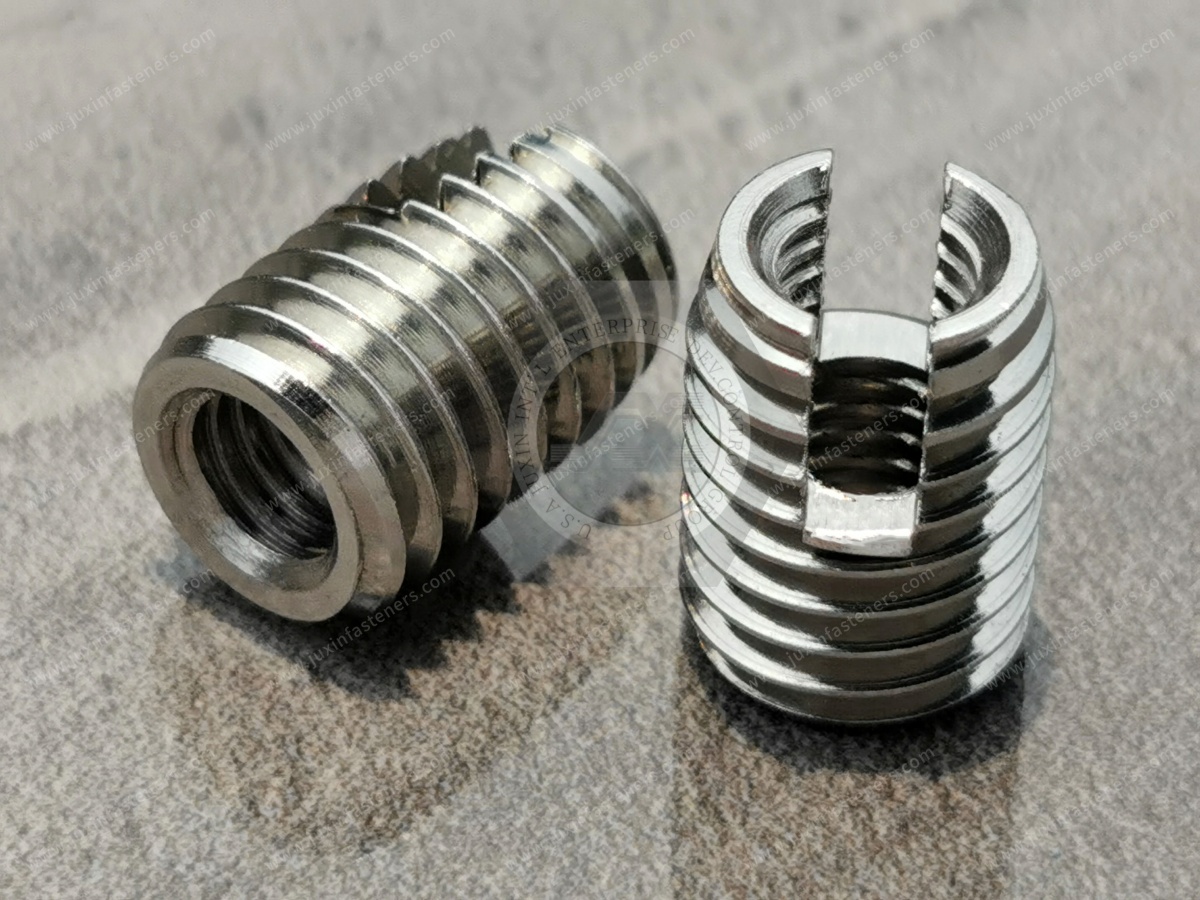
302-style inserts are commonly associated with a slotted self tapping design.
The cutting slot at the installation end creates cutting edges that establish the insert's external engagement as it is driven into the prepared hole.
Depending on the exact product specification, this general geometry may be considered for suitable:
aluminum alloys;
non-ferrous metals;
engineering plastics;
cast materials;
industrial components.
The slot influences:
cutting action;
chip formation;
installation torque;
engagement with the parent material.
Selection should consider whether the parent material can accommodate the installation stresses produced by the insert.
For brittle materials or compact bosses, pilot-hole diameter and surrounding material become especially important.
Consider this type when:
a conventional self tapping insert architecture is suitable;
sufficient radial space is available;
the parent material is compatible with the cutting geometry;
a solid reusable internal thread is required;
the receiving hole can be controlled appropriately.
Do not assume that every supplier's “302” insert is dimensionally interchangeable.
Always compare the drawing.
A flanged version adds a head or flange at one end of the insert.
Depending on the application, a flange can provide:
a defined seating surface;
controlled installation position;
increased bearing area at the component surface;
resistance to installation beyond the intended seating position.
However, a flange does not automatically guarantee higher pull-out strength in every assembly.
Pull-out performance still depends on:
external engagement;
insert length;
parent material;
pilot-hole geometry;
surrounding material;
loading direction.
The flange should therefore be treated as part of the complete joint geometry rather than simply a “stronger version.”
Thin-wall self tapping inserts reduce the radial envelope between the internal thread and the outside of the insert.
This can be useful where component geometry provides limited space around the required machine thread.
Potential applications may include compact:
engineering plastic components;
aluminum housings;
electronic equipment;
instrumentation;
lightweight assemblies.
A smaller outside diameter can help preserve parent material, but less insert wall section may also change:
insert stiffness;
installation behavior;
cutting geometry;
mechanical capacity.
A thin-wall design should therefore not be selected simply because “smaller is better.”
The engineer should evaluate:
Required Internal Thread → Available Outside Diameter → Insert Wall → Parent Material → Installation Load → Service Load
307/308-style inserts are commonly associated with cutting-hole geometries rather than the conventional single-slot architecture.
The openings create cutting edges that interact with the parent material during installation.
Depending on the exact design, this geometry can provide different cutting and chip-management behavior from a slotted insert.
Potential applications can include suitable:
aluminum castings;
non-ferrous components;
industrial machinery;
engineering plastics;
other materials validated for the specific insert geometry.
This is a more useful engineering comparison than asking which series is “stronger.”
Potential characteristics include:
relatively simple cutting architecture;
defined cutting slot;
straightforward solid-insert design.
Potential characteristics include:
multiple cutting regions;
different chip formation;
different installation torque behavior;
different interaction with the parent material.
The correct choice depends on:
parent-material hardness;
ductility;
brittleness;
pilot-hole diameter;
insert size;
wall thickness;
installation process.
Neither geometry should be described as universally superior.
Flanged variants combine cutting-hole-style insert geometry with a seating flange.
They may be useful where the assembly requires:
controlled seating position;
increased surface bearing area;
positive installation stop;
specific component interface geometry.
Again, the flange should not be treated as a universal mechanical-performance upgrade.
The external engagement and parent material remain responsible for much of the insert's resistance to extraction and rotation.
Series numbering alone should not be used as an engineering specification.
Depending on the product system, differences can involve dimensions, length relationships, external geometry, or intended material/application ranges.
When sourcing a 307 or 308 insert from an alternative supplier, request or compare:
internal thread;
external geometry;
outside diameter;
overall length;
cutting-hole dimensions;
installation end geometry;
material;
finish;
recommended pilot hole;
installation tooling.
This is more reliable than assuming the same series number guarantees interchangeability.
Some product systems include additional self tapping insert series such as 317 or 318.
These designations should be treated as product-family references rather than universal international standards.
Do not specify a 317 or 318 insert solely from the series number.
Instead define the required:
internal thread;
external geometry;
insert length;
material;
finish;
receiving hole;
installation method;
required mechanical performance.
Where anti-rotation or additional locking features are involved, the actual feature and its installation method should be shown on the drawing.
Blind-hole applications create different engineering constraints from through holes.
The key issues include:
available hole depth;
chip evacuation;
insert installation depth;
material beneath the insert;
tool clearance;
contamination requirements.
Where an insert family is marketed for blind-hole applications, engineers should verify exactly how the cutting geometry manages displaced material or chips.
A “blind-hole insert” should not automatically be interpreted as a hermetically sealed or leak-tight fastener.
Those are separate engineering requirements.
Not automatically.
A solid threaded insert may fit tightly into the parent material, but mechanical engagement alone does not establish a validated pressure seal.
Leak performance can depend on:
thread geometry;
surface finish;
porosity of the parent material;
insert interface;
sealants;
O-rings;
pressure;
temperature;
fluid or gas;
manufacturing variation.
If airtightness, watertightness, or pressure sealing is required, it should be treated as a separate engineering specification and validated accordingly.
The parent material should influence insert selection from the beginning.
Consider:
alloy;
cast vs wrought condition;
hardness;
available wall thickness;
required load;
corrosion environment.
Consider:
polymer family;
glass reinforcement;
brittleness;
creep;
operating temperature;
molded boss geometry.
Consider:
brittleness;
porosity;
local wall thickness;
edge distance;
cracking risk.
Consider both:
mechanical engagement;
galvanic compatibility.
The insert geometry that installs successfully into one material should not automatically be transferred to another without review.
The pilot hole is not merely an installation detail.
It directly influences:
cutting load;
installation torque;
external engagement;
radial stress;
cracking risk;
pull-out performance;
torque-out performance.
Potential results include:
excessive installation torque;
insert deformation;
tool overload;
parent-material cracking;
boss expansion;
difficult installation.
Potential results include:
reduced engagement;
insert rotation;
lower pull-out resistance;
lower torque-out resistance;
inconsistent positioning.
For this reason, the correct insert type and correct pilot hole should be selected together.
Hole adjustment can influence installation torque, but increasing the hole diameter also reduces external engagement.
Therefore, a harder parent material should trigger a complete review of:
insert geometry;
pilot hole;
cutting features;
installation torque;
parent-material cracking risk;
required retention.
The objective is not simply to make installation easier.
The objective is to establish a repeatable installation while retaining the required mechanical performance.
Insert outside diameter determines how much parent material remains around the installation.
For compact components, this can become the limiting factor.
Engineers should evaluate:
insert OD;
pilot-hole diameter;
boss OD;
surrounding wall;
edge distance;
adjacent features.
A larger insert may provide more external engagement but can leave less parent material around the hole.
A smaller thin-wall insert may preserve more parent material but has its own structural and installation constraints.
This is a genuine design trade-off.
Longer inserts can provide additional engagement area, but “longer” does not automatically mean “better.”
Available component depth, loading, installation geometry, and material must be considered.
An unnecessarily long insert may:
require a deeper hole;
interfere with adjacent features;
increase installation torque;
add cost;
provide no useful mechanical benefit beyond the effective load-transfer region.
Insert length should therefore be selected according to the required joint rather than maximized automatically.
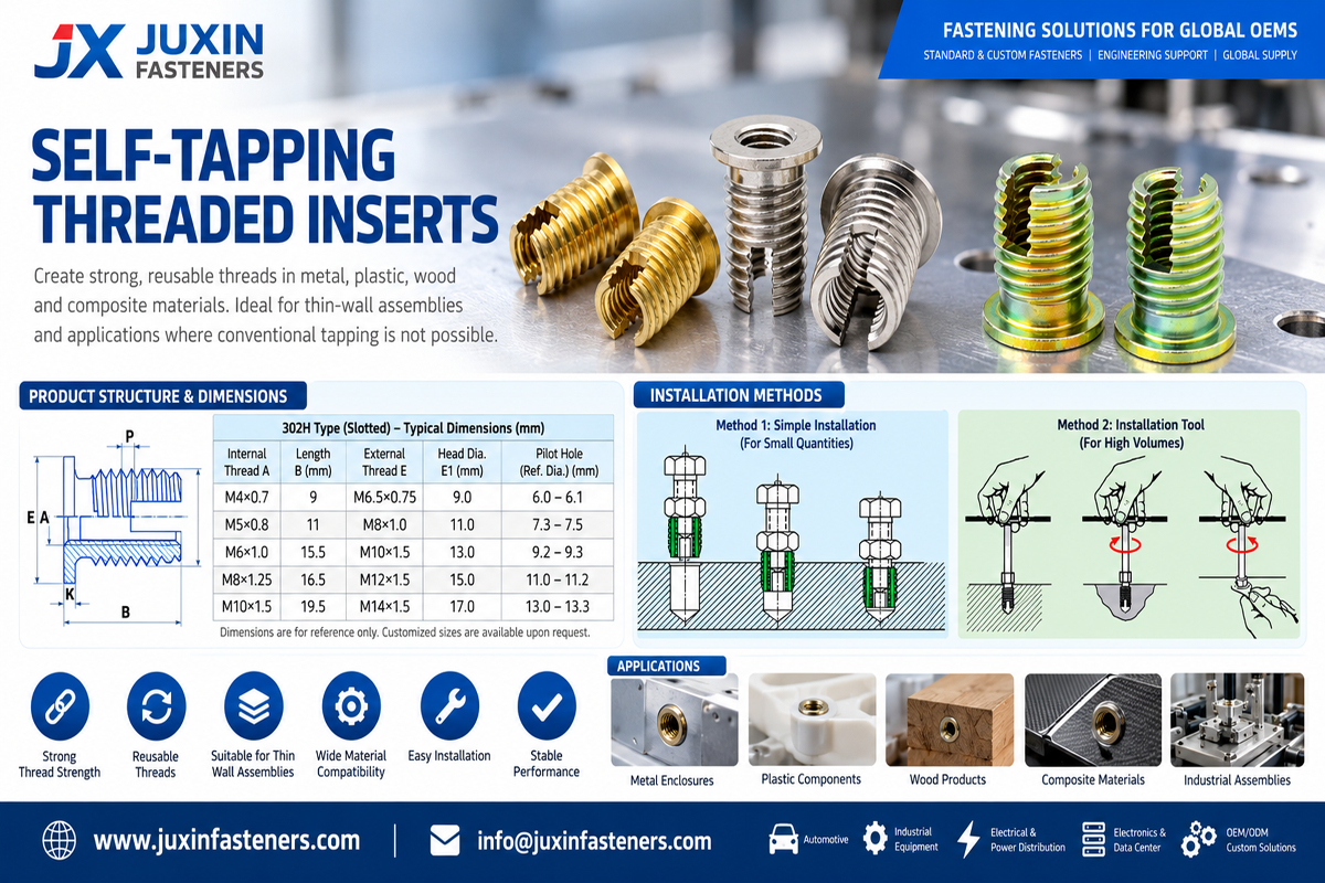
May be appropriate when:
installation depth is controlled by tooling;
flush or below-surface installation is required;
the component does not need an external seating flange.
May be considered when:
a positive seating surface is useful;
surface bearing area is required;
installation depth benefits from a physical stop;
component geometry is designed for the flange.
The flange can change the assembly interface, so interchangeability should not be assumed.
Can provide more freedom for:
chip exit;
installation depth;
tooling.
Requires careful control of:
hole depth;
insert length;
chip space;
tool clearance;
material below the insert.
For blind holes, verify that the insert cannot bottom before reaching the specified installed position.
Pull-out describes resistance to axial extraction from the parent material.
Factors include:
insert length;
external thread geometry;
parent-material strength;
pilot-hole diameter;
wall thickness;
installation quality.
Torque-out describes resistance to rotation of the insert within the parent material.
Factors include:
external cutting geometry;
parent material;
pilot-hole condition;
engagement length;
installation quality;
mating screw torque.
An insert can perform differently under axial and rotational loading.
Therefore, “high strength” should not be used as the only performance specification.
Installation torque can provide useful process information.
Abnormally high installation torque may indicate:
undersized pilot hole;
harder-than-expected parent material;
poor hole quality;
incorrect insert;
tool misalignment.
Abnormally low installation torque may indicate:
oversized pilot hole;
damaged parent material;
incorrect insert geometry;
insufficient engagement.
For controlled OEM assembly, monitoring installation behavior can help identify process variation before the mating screw is installed.
Not automatically.
The insert's external engagement secures the insert to the parent component.
Loosening of the mating screw is a different failure mode.
Screw loosening depends on:
preload;
joint stiffness;
transverse movement;
friction;
screw geometry;
bearing surfaces;
locking method;
service vibration.
If anti-loosening performance is required, the complete bolted joint should be engineered accordingly.
Both technologies can reinforce or repair threads, but their architectures are different.
| Engineering Factor | Self Tapping Solid Insert | Helical Wire Insert |
|---|---|---|
| Insert construction | Solid body | Formed wire coil |
| Receiving hole | Prepared pilot hole | Prepared hole plus dedicated insert tap |
| External insert thread tapping | Normally not required | Required |
| Radial space | Depends on insert OD | Depends on repair system |
| Installation sequence | Relatively direct | Drill/tap/install sequence |
| Internal machine thread | Yes | Yes |
| Thread repair | Possible | Possible |
| New thread reinforcement | Possible | Possible |
The choice should not be based on a generic “better/worse” ranking.
Consider:
available wall thickness;
parent material;
repair vs new design;
installation equipment;
service procedure;
required mechanical performance;
production volume.
Related Engineering Guide: Self Tapping Screw Sleeves for Thread Repair
For thermoplastic components, another important comparison is self tapping vs heat set installation.
May be considered where:
mechanical installation is preferred;
field installation or repair is required;
the parent material can support the cutting/forming process.
May be considered where:
the parent material is a suitable thermoplastic;
controlled thermal insertion is available;
the molded boss is designed for polymer flow around the insert.
Related Engineering Guide: Heat Set Inserts for Plastic
These technologies solve different assembly problems.
A self tapping insert requires sufficient parent-material thickness for its external engagement.
A rivet nut is specifically useful for sheet or hollow structures where a threaded connection must be installed from one side.
For genuinely thin sheet metal, a blind rivet nut may therefore be more appropriate than a conventional self tapping insert.
Related Product: Blind Rivet Nuts for Thin Sheet and Hollow Structures
An M5 insert is not fully defined by “M5.”
Outside geometry determines the required component space and installation process.
302, 303, 307, 308 and similar designations may be widely recognized in particular product families, but engineering interchangeability should be confirmed from drawings.
An insert selected for aluminum may not install identically in glass-filled polymer or a brittle casting.
Larger OD is not automatically better if it leaves insufficient parent material.
A flange changes seating and load distribution but does not automatically solve pull-out or torque-out requirements.
Installation behavior can reveal an unsuitable hole/insert/material combination.
Thread retention and pressure sealing are separate engineering requirements.
| Design Condition | Insert Feature to Evaluate |
|---|---|
| General thread reinforcement | Slotted or cutting-hole self tapping insert |
| Limited radial space | Thin-wall insert |
| Defined surface seating | Flanged insert |
| Blind-hole assembly | Blind-hole-compatible geometry |
| High rotational loading | External geometry and torque-out performance |
| High axial loading | Engagement length and pull-out performance |
| Brittle parent material | Pilot hole, radial stress and boss geometry |
| Compact boss | Insert OD and remaining wall thickness |
| Repair application | Existing damage and remaining parent material |
| Corrosive environment | Insert material, finish and galvanic compatibility |
This table is a starting point for engineering review—not a substitute for application validation.
Potential applications include suitable:
aluminum housings;
electronic module housings;
thermal-management components;
machinery-related components;
lightweight structural assemblies;
serviceable threaded interfaces.
Selection should be based on the actual component drawing and customer requirements.
Potential applications include:
converter and inverter housings;
control equipment;
power electronics;
electrical enclosures;
thermal-management hardware.
Where relevant, consider electrical continuity, grounding, isolation, corrosion, and service temperature.
Applications can include:
machine housings;
automation equipment;
actuator components;
fixtures;
hydraulic equipment;
serviceable assemblies.
Repeated maintenance makes reusable internal threads valuable in these applications.
Selected inserts may be used in suitable:
equipment housings;
interior assemblies;
mechanical equipment;
aluminum components;
serviceable systems.
Rail suitability depends on the specific component, load, material, environmental exposure, vibration, maintenance requirements, and customer specifications.
Applications can include:
electronic housings;
communication equipment;
control systems;
instrumentation;
server-related hardware.
Compact component geometry can make insert OD and wall thickness particularly important.
A self tapping insert drawing or purchasing specification should define, as applicable:
internal thread;
thread pitch;
insert series or geometry;
outside diameter;
overall length;
external cutting features;
flange dimensions;
insert material;
surface finish;
installation direction;
parent material;
recommended receiving-hole diameter;
installed position;
required pull-out performance;
required torque-out performance;
inspection requirements.
If a customer is qualifying a second source, provide the original drawing rather than only the supplier's series number.
Relevant product inspections can include:
internal thread;
outside diameter;
overall length;
flange dimensions;
cutting slot or cutting-hole geometry;
material;
surface finish;
visual condition.
Internal threads may be inspected using appropriate GO/NO-GO thread gauges according to the specified thread system.
Dimensional conformity should then be combined with application validation where the parent material and installation process significantly influence performance.
Self tapping inserts are frequently cross-sourced using an existing supplier's series number.
This creates a common procurement risk:
same series description ≠ automatically identical part
Before approving an alternative source, compare:
Internal thread.
Insert OD.
Insert length.
External thread profile.
Cutting slot/hole geometry.
Flange geometry.
Installation end.
Material.
Finish.
Receiving-hole recommendation.
Installation tooling.
Required mechanical performance.
Samples should be installed in representative parent material before mass-production approval when the application is mechanically important.
Purchasing managers, strategic sourcing teams, and supplier-development engineers should evaluate more than unit price.
Important supplier capabilities can include:
engineering drawing review;
dimensional inspection;
internal thread-gauge inspection;
material specification control;
finish control;
sample qualification;
lot traceability where required;
packaging control;
engineering change management;
prototype-to-production consistency;
custom geometry capability.
For OEM projects, sourcing the correct insert geometry is more important than purchasing the cheapest insert with the same nominal internal thread.
For efficient engineering review and quotation, provide:
required internal thread;
thread pitch;
metric or Unified inch thread;
insert series or reference part number;
complete drawing where available;
outside diameter;
overall length;
flange requirement;
insert material;
surface finish;
parent material;
parent-material grade where known;
pilot-hole diameter;
hole depth;
boss diameter or wall thickness where critical;
blind or through hole;
required pull-out load if specified;
required torque-out value if specified;
mating screw torque;
operating environment;
corrosion requirement;
installation method;
sample quantity;
production quantity;
estimated annual demand;
documentation requirements;
traceability requirements;
packaging requirements.
For second-source projects, send the existing insert drawing and current application information whenever possible.
They generally represent different external cutting geometries, such as slotted versus cutting-hole designs. Exact geometry and dimensions should be confirmed from the applicable drawing because series numbers alone do not guarantee interchangeability.
A thin-wall insert uses a smaller radial envelope around the internal thread, which can be useful where limited parent material is available.
Mechanical and installation requirements still need to be validated.
A flanged insert has an enlarged seating feature at one end. The flange can help define installed position and distribute surface bearing load, depending on the component design.
No. Mechanical performance depends on external engagement, parent material, pilot hole, insert length, loading direction, and installation quality.
Yes, aluminum is a common parent material. Alloy, hardness, casting condition, wall thickness, hole size, load, and corrosion environment should be considered.
Yes, for suitable plastics and component geometries. Polymer type, reinforcement, creep, brittleness, boss geometry, temperature, and installation stress should be evaluated.
Choose an insert geometry specifically suitable for the available blind-hole depth and chip-management requirements. Verify hole depth, insert length, tool clearance, and material beneath the insert.
They are commonly used as product-series designations in parts of the threaded insert market,
but engineers should not rely on the number alone as a complete international dimensional specification. Use the actual drawing.
Normally no external receiving thread is pre-tapped. A correctly sized pilot hole is prepared and the insert establishes its external engagement during installation.
Yes, appropriate self tapping inserts can be used for many repair applications if sufficient sound parent material remains around the damaged hole.
Not automatically. Mechanical thread engagement and pressure sealing are different requirements. If leakage control is required, specify and validate the sealing system separately.
That depends on the application. Axial loads emphasize pull-out performance, while high screw tightening or rotational loads can emphasize torque-out performance. Some applications require both.
Use contextual internal links from this page to:
Self Tapping Screw Sleeves for Thread Repair
Self Tapping Thread Inserts for Plastic and Aluminum
Tapping Inserts for Soft Metal
Heat Set Inserts for Plastic
Wire Thread Inserts and Helical Thread Repair
Blind Rivet Nuts for Thin Sheet
Self-Clinching Nuts, Studs and Standoffs
Drawing-Based Custom Fasteners and CNC Machined Components
Use the existing indexed JUXIN FASTENERS URLs when implementing these links.
Selecting a self tapping insert is ultimately a geometry-matching problem between the insert, parent component, installation process, and required mechanical performance.
JUXIN FASTENERS supports industrial customers sourcing slotted self tapping inserts, cutting-hole inserts, thin-wall inserts, flanged inserts, thread repair inserts, and drawing-based threaded insert solutions.
For engineering projects, provide the parent material, required internal thread, available component geometry, receiving-hole dimensions, installation method, and mechanical requirements.
For procurement development, supplier qualification, and second-source programs, provide the existing insert drawing or reference part number, material, finish,
sample quantity, production quantity, estimated annual demand, inspection requirements, documentation requirements, traceability requirements, and packaging requirements.
Where an existing supplier's 302, 303, 307, 308 or related series is being cross-referenced, send the complete drawing
whenever possible so dimensional and application compatibility can be reviewed before sample qualification.
Email: info@juxinfasteners.com
Website: www.juxinfasteners.com
Contact Us
Tel.:
+86 020 8621 0320
+86 020 3121 6067
E-mail:
Technical Support:
Navigation
SEND INQUIREY