Call Us
+86 136 6007 9809
Call Us
+86 136 6007 9809

Nov. 22, 2023
Self tapping screw sleeves provide a solid metal internal thread in components where the original parent-material thread is damaged,
worn, stripped, or insufficient for the required service condition.
Also known as self tapping threaded inserts, self tapping inserts, solid thread repair inserts, or thread repair sleeves,
these components use an external self-tapping geometry to establish engagement in a correctly prepared receiving hole while maintaining the required internal machine thread for the mating screw.
They can be considered for suitable aluminum alloys, cast materials, engineering plastics, copper alloys,
magnesium alloys, and other parent materials where sufficient surrounding material remains to support the insert.
For maintenance engineers, however, thread repair is not simply a matter of drilling out a damaged hole and installing a larger insert.
A reliable repair requires evaluation of:
the original thread;
the actual damaged-hole diameter;
remaining parent material;
insert outside diameter;
engagement length;
wall thickness;
edge distance;
installation torque;
required screw tightening torque;
axial and rotational loading;
service environment.
JUXIN FASTENERS supplies self tapping screw sleeves, self tapping threaded inserts, thread repair inserts, helical thread inserts,
and drawing-based threaded components for industrial OEM, machinery, automotive, electrical equipment, automation, transportation, and maintenance applications.
This guide focuses specifically on thread repair and thread restoration engineering—how to determine whether a damaged hole can be repaired,
how self tapping screw sleeves differ from other repair methods, what causes repair failures, and what engineering and procurement teams should specify before sourcing a replacement insert.
A self tapping screw sleeve can repair a damaged internal thread by replacing the compromised parent-material thread with a larger external insert interface while retaining the required internal machine thread.
The basic repair sequence is:
Inspect the damaged threaded hole.
Determine whether sufficient sound parent material remains.
Prepare the hole to the required diameter and depth.
Install the self tapping sleeve using appropriate tooling.
Allow the external cutting or forming geometry to establish engagement with the parent material.
Verify installed depth, alignment, and internal thread condition.
Reinstall the mating screw according to the validated assembly requirement.
When the repair is correctly engineered, the mating screw can often continue using the original nominal thread size because the insert provides that internal thread.
However, this is possible only when the damaged component still provides sufficient material for the larger outside diameter of the insert.
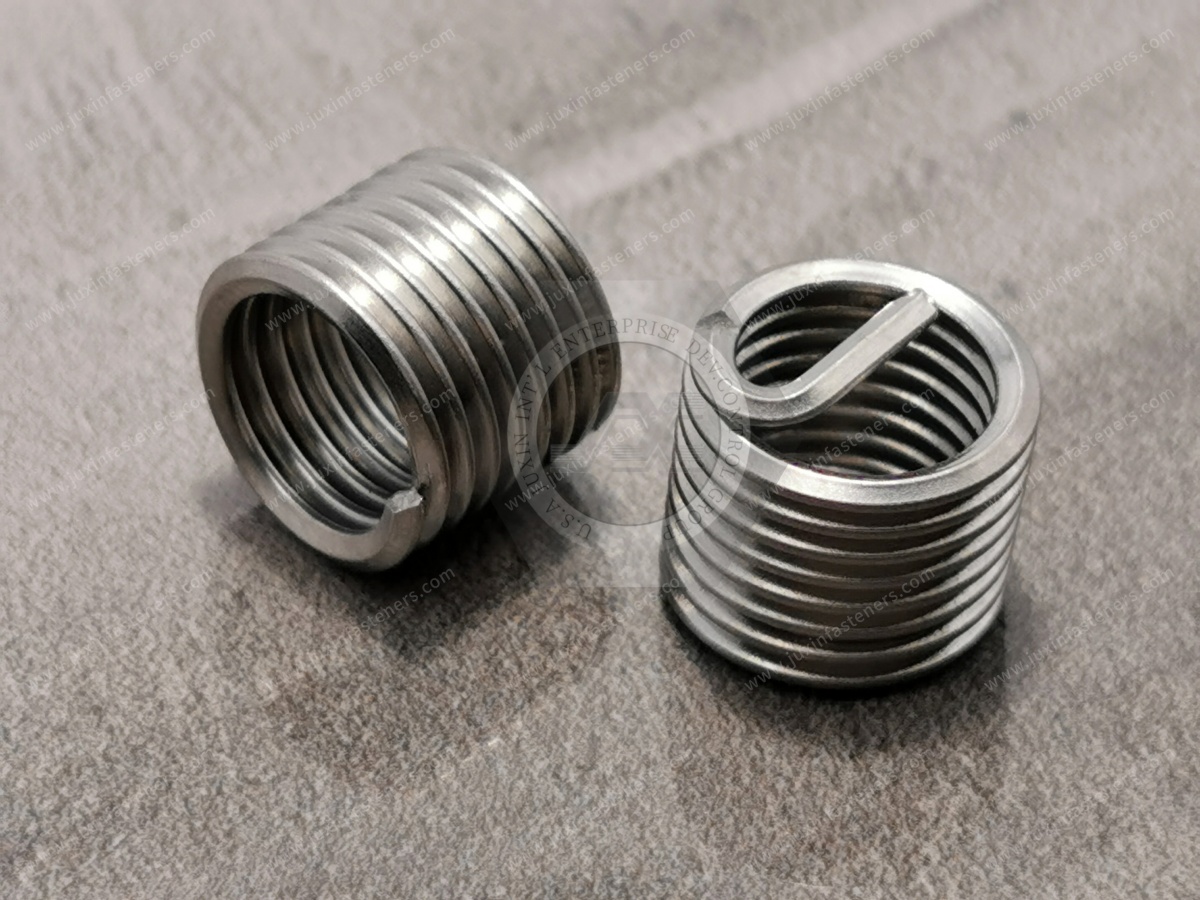
A self tapping screw sleeve is a solid threaded insert containing:
an internal machine thread;
an external self-tapping geometry;
cutting slots, cutting holes, or other installation features depending on design;
a solid metal body.
Unlike insert systems that require a specially tapped external receiving thread, a self tapping insert creates its own external engagement during installation into a correctly sized prepared hole.
The term “screw sleeve” is used in some industrial markets, while engineers and procurement teams may also search for:
self tapping thread insert;
self tapping threaded insert;
solid threaded insert;
thread repair insert;
stripped thread repair insert;
thread repair sleeve;
threaded insert for aluminum repair;
threaded insert for cast components;
screw thread repair insert.
Because terminology differs between suppliers, the actual dimensions and installation geometry should be defined by drawing or specification when interchangeability is important.
Self tapping inserts can be used both in new designs and for repairing existing components, but the engineering conditions are different.
For a new component, engineers can design the:
pilot hole;
boss;
wall thickness;
edge distance;
installation depth;
around the insert from the beginning.
For an existing damaged component, the designer inherits whatever damage already exists.
The repair process must therefore answer a different question:
Is there enough undamaged parent material remaining to create a reliable new load path?
This is the central engineering question in thread repair.
A stripped thread should not automatically be treated as a nominal-size hole.
Damage may include:
partial thread stripping;
complete thread stripping;
ovality;
cross-thread damage;
cracking;
corrosion;
material breakout;
previous repair damage;
enlarged hole diameter.
The remaining hole should be inspected before selecting the insert.
For critical repairs, useful information can include:
original nominal thread;
original hole location;
current minimum and maximum hole diameter;
available hole depth;
surrounding wall thickness;
distance to the nearest edge;
parent-material condition.
This determines whether a standard repair insert still has enough material to engage.
Often, yes.
One major benefit of a thread repair insert is the ability to provide the original internal machine thread while using a larger outside diameter to engage fresh parent material.
For example, a damaged M6 parent thread may potentially be repaired using an insert with an M6 internal thread and a larger external engagement diameter.
But retaining the original screw size is not automatic.
The engineer must verify:
Damaged Hole Diameter < Required Insert Engagement Envelope < Available Parent Material
If the existing damage extends beyond the outside engagement diameter of the proposed insert, a larger repair solution or a different repair method may be required.
This is an important question that generic thread-repair articles often overlook.
A standard self tapping insert may not be appropriate when:
the hole has been severely enlarged;
the hole is strongly oval;
the parent material has cracked;
insufficient wall thickness remains;
the hole is too close to an edge;
a previous repair removed additional material;
corrosion has weakened the surrounding structure.
In these situations, simply installing a larger insert can make the problem worse.
Alternative options may include:
a larger repair insert;
a specially designed stepped insert;
a different threaded insert system;
component machining and restoration;
replacement of the component.
The correct decision depends on the structural importance and economics of the part.
The same insert does not behave identically in every material.
Aluminum is a common thread-repair application because direct aluminum threads can be damaged through repeated assembly, cross-threading, excessive torque, or wear.
Before repair, consider:
alloy;
cast or wrought condition;
hardness;
remaining material;
hole geometry;
required screw torque;
service load.
A cast aluminum housing with porosity or local damage should not automatically be treated like a sound wrought aluminum component.
Cast components can benefit from threaded inserts, but brittleness, porosity, microstructure, and remaining wall thickness must be considered.
Excessive installation stress can cause local cracking or breakout.
Self tapping inserts can repair or reinforce threads in suitable plastics.
Relevant factors include:
polymer;
reinforcement;
creep;
brittleness;
boss geometry;
operating temperature;
remaining material after damage.
For thermoplastic production components, heat-set inserts may also be worth evaluating when the component and process allow thermal installation.
Thread repair may be possible in lightweight alloys, but both mechanical and corrosion compatibility require attention.
Dissimilar-metal combinations exposed to moisture may require an assembly-level galvanic corrosion evaluation.
For new production, the receiving hole can be manufactured specifically for the insert.
For thread repair, the existing damage may already determine part of the hole geometry.
The repair hole must therefore be sized to:
remove damaged thread material where necessary;
provide sufficient engagement for the insert;
avoid excessive removal of sound parent material;
maintain enough surrounding wall thickness.
Potential consequences include:
excessive installation torque;
insert damage;
tool overload;
cracking;
boss expansion;
parent-material breakout.
Potential consequences include:
insufficient external engagement;
insert rotation;
reduced pull-out resistance;
reduced torque-out resistance;
inconsistent installation.
The correct repair-hole diameter should be determined from the actual insert geometry and parent material.
A repair can fail even when the receiving hole diameter appears correct.
The insert's larger outside diameter changes how loads are transferred into the component.
Engineers should verify:
remaining wall thickness;
boss outside diameter;
edge distance;
depth below the insert;
nearby holes;
ribs or thin sections.
If the repaired hole is near an edge, increasing the insert diameter may reduce the remaining ligament of material to an unacceptable level.
This is why a thread repair insert should be treated as a structural modification to the threaded interface rather than merely a replacement thread.
Blind holes introduce another constraint: available depth.
The repair design must accommodate:
insert length;
installation-tool geometry;
chip or material clearance where applicable;
required installed depth;
material remaining beneath the insert.
If the insert bottoms before reaching its specified position, installation torque may increase sharply and damage the component.
For blind holes, depth should therefore be verified before repair machining begins.
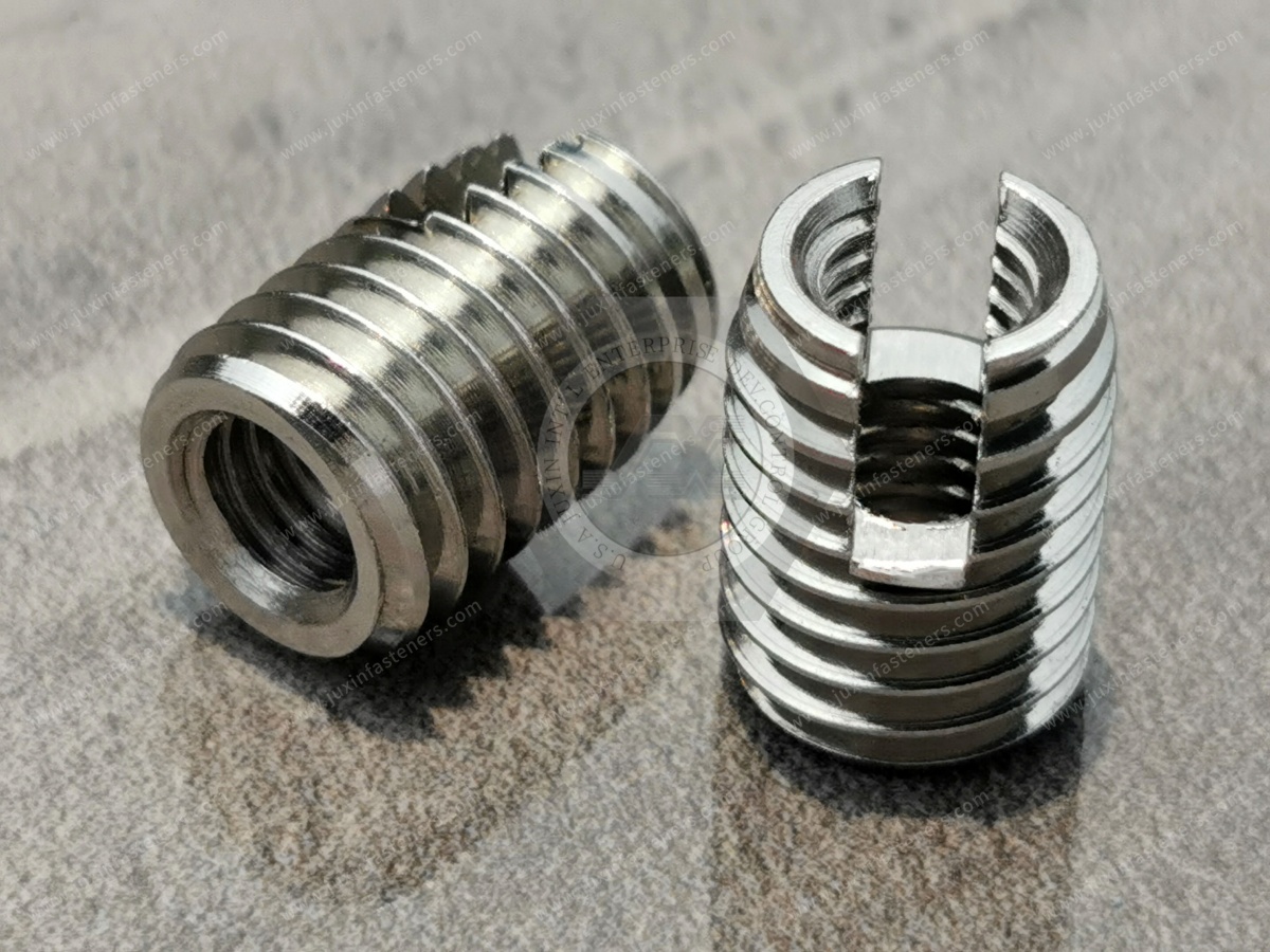
Slotted inserts use a cutting slot near the installation end.
The cutting feature helps establish the insert's external engagement as it enters the prepared hole.
Depending on the product geometry and parent material, this configuration may be suitable for:
aluminum;
selected non-ferrous materials;
suitable plastics;
cast components.
For replacement sourcing, compare:
internal thread;
external thread geometry;
overall length;
outside diameter;
slot geometry;
material;
finish;
recommended receiving hole.
Another common solid insert configuration uses cutting holes or cutting openings around the body.
Certain industrial product families are often referenced with series-style terminology.
When qualifying an alternative supplier, the series name alone is not enough.
Compare:
internal thread;
external engagement geometry;
insert length;
outside diameter;
cutting-hole geometry;
installation direction;
material;
surface treatment;
receiving-hole recommendation;
mechanical requirements.
This is particularly important in maintenance programs where a substitute insert must fit an established repair procedure.
Both technologies can repair damaged threads, but they use different installation architectures.
Typically:
uses a solid insert body;
installs into a correctly prepared hole;
creates its own external engagement;
does not normally require a specially tapped insert-receiving thread.
Typically:
requires drilling to the specified repair diameter;
requires a dedicated insert tap;
uses a wire coil installed into the specially prepared thread;
provides the required internal machine thread after installation.
Neither system is universally better.
Selection should consider:
remaining parent material;
available wall thickness;
required internal thread;
installation equipment;
repair environment;
component value;
required mechanical performance;
established maintenance procedures.
Related Engineering Guide: Wire Thread Inserts and Helical Thread Repair
Another repair method is to enlarge the damaged thread and use a larger screw.
This can be simple, but it changes the mating fastener and potentially the complete assembly.
A self tapping repair insert may be preferred when retaining the original screw size is important for:
interchangeability;
service procedures;
assembly standardization;
replacement parts;
mating component geometry.
Oversize tapping may remain practical where changing the fastener size does not create a design or service problem.
Not every damaged thread should be repaired.
For low-cost components, replacement may be more economical than:
inspection;
machining;
insert installation;
validation.
Thread repair becomes particularly valuable when the component is:
expensive;
difficult to replace;
part of a larger assembly;
subject to long replacement lead times;
costly to remove from service.
Maintenance teams should therefore evaluate total repair economics rather than insert cost alone.
A repaired thread can fail in different ways.
Axial load extracts the insert from the parent material.
Relevant variables include:
engagement length;
external geometry;
parent-material strength;
receiving-hole diameter;
remaining material;
installation quality.
Applied rotational load causes the insert to rotate in the repaired hole.
Relevant variables include:
external engagement geometry;
cutting features;
hole condition;
parent material;
installation quality;
mating screw torque.
A repair that resists axial loading is not automatically resistant to rotational failure.
Where the joint is mechanically important, the required failure mode and acceptance criteria should be defined.
Not automatically.
The insert provides a stable internal thread and an interface with the parent material.
Loosening of the mating screw under vibration is a separate bolted-joint issue influenced by:
preload;
transverse movement;
friction;
joint stiffness;
screw properties;
bearing surfaces;
locking method;
assembly torque.
If vibration loosening is a concern, evaluate the complete joint and consider an appropriate locking strategy.
Do not rely on the thread repair insert alone as a vibration-locking mechanism.
Possible causes include:
repair hole too large;
insufficient remaining parent material;
inadequate engagement;
unsuitable insert geometry;
excessive mating screw torque;
installation damage.
Possible causes include:
repair hole too small;
insufficient wall thickness;
inadequate edge distance;
brittle parent material;
excessive installation torque;
pre-existing cracks.
Possible causes include:
insufficient engagement length;
weak or damaged parent material;
oversized receiving hole;
inadequate remaining wall;
service load above the validated condition.
Possible causes include:
damaged or irregular original hole;
poor tool alignment;
unsuitable installation tooling;
incorrect starting technique.
Misalignment can cause mating screw problems and uneven load transfer.
Potential causes include:
contaminated repair hole;
installation debris;
tool damage;
cross-threading;
incorrect mating screw;
excessive tightening torque.
Determine:
original thread size;
damage severity;
current hole geometry;
parent material;
available depth;
wall thickness;
edge distance.
Choose according to:
required internal thread;
available outside diameter;
parent material;
engagement length;
installation method;
mechanical requirements.
Machine the hole according to the insert requirement.
Control:
diameter;
straightness;
depth;
alignment;
surface condition.
Remove debris that could interfere with installation or the internal thread.
For controlled industrial production or maintenance, use tooling appropriate to the insert design.
Maintain:
axial alignment;
controlled rotation;
appropriate installation torque;
specified installation depth.
Manual installation methods may be suitable for some repair situations, but production processes benefit from repeatable dedicated tooling.
Check:
insert depth;
alignment;
internal thread;
parent-material cracking;
insert stability;
surface condition.
Confirm:
correct mating screw;
thread engagement;
required assembly torque;
absence of cross-threading;
required service performance.
There is no universal lubricant recommendation for every self tapping insert.
Lubrication can change:
installation torque;
cutting behavior;
friction;
chip formation;
contamination risk;
final assembly conditions.
The decision should depend on:
insert material;
parent material;
insert geometry;
manufacturer's process recommendation;
cleanliness requirements;
downstream assembly requirements.
For cleanliness-sensitive electrical, semiconductor, optical, medical, or other controlled applications,
introducing an unapproved cutting fluid or lubricant can create additional contamination concerns.
Therefore, lubrication should be treated as a validated process variable—not a generic installation step.
Steel inserts are suitable for many industrial repair and reinforcement applications.
Potential benefits include:
mechanical strength;
wear resistance;
machinability;
cost efficiency.
Depending on environmental requirements, surface treatments may include zinc-based or other customer-specified coatings.
Selection should consider both corrosion requirements and compatibility with the parent material.
Stainless steel inserts may be selected where corrosion resistance or customer material requirements justify their use.
Depending on product geometry and specification, materials can include grades such as:
304 stainless steel;
316 stainless steel.
Stainless steel should not automatically be described as corrosion-proof.
Performance depends on:
environment;
grade;
contaminants;
mating materials;
temperature;
crevice conditions;
galvanic interactions.
Installing a dissimilar metal insert into aluminum creates a multi-material interface.
Where moisture or another electrolyte is present, engineers should evaluate galvanic corrosion risk.
Relevant variables include:
insert material;
aluminum alloy;
surface finish;
exposed area ratio;
environmental exposure;
drainage;
coating damage;
service life.
For outdoor, transportation, electrical, or other corrosive environments, material and coating selection should therefore be evaluated at assembly level.
Self tapping repair inserts can be considered for suitable:
aluminum housings;
machinery-related vehicle components;
electrical enclosures;
electronic modules;
maintenance and service repairs.
The insert should be qualified according to the specific component and customer requirements.
A generic insert should not automatically be treated as automotive-qualified.
Thread repair is particularly valuable for machinery because equipment may remain in service for many years and undergo repeated maintenance.
Applications can include:
machine housings;
hydraulic equipment;
automation systems;
fixtures;
actuator assemblies;
serviceable covers;
aluminum equipment components.
Repairing a threaded interface can reduce the need to replace a larger, higher-value component.
Potential applications include repair or reinforcement of threaded interfaces in:
electrical housings;
power electronic enclosures;
control equipment;
converter and inverter housings;
communication equipment;
industrial electronics.
Where electrical performance is relevant, engineers should also evaluate:
grounding;
electrical continuity;
isolation;
coating;
corrosion.
Long-life transportation equipment often requires maintainable fastening systems.
Thread repair inserts may be useful in appropriate housings, equipment, interior systems, and serviceable components.
Actual suitability depends on:
component function;
parent material;
structural loading;
vibration;
environmental exposure;
maintenance procedure;
customer specifications.
Testing becomes more important when:
the component is structurally important;
the remaining material is limited;
the repair carries significant axial load;
screw torque is high;
vibration or shock is severe;
the repaired component is expensive or safety-related;
a new repair process is being introduced into production.
Depending on the application, customer-defined validation may include:
installation torque monitoring;
pull-out testing;
torque-out testing;
mating screw torque testing;
repeated assembly testing;
vibration testing of the complete joint;
environmental or corrosion testing.
The validation method should represent the actual service requirement.
For repeat maintenance or OEM rework, the repair should be documented rather than left to operator judgment.
A controlled repair specification may define:
original thread;
repair insert part number;
repair-hole diameter;
hole tolerance;
hole depth;
installation tool;
installed depth;
insert orientation where relevant;
inspection method;
mating screw;
assembly torque;
acceptance criteria.
This turns a one-time repair into a repeatable industrial process.
Procurement teams sourcing repair inserts should consider more than nominal thread size.
Important questions include:
Is the insert dimensionally interchangeable with the existing repair system?
What is the outside engagement geometry?
What repair-hole diameter is required?
Is special installation tooling required?
Can samples be evaluated before production orders?
Are internal threads inspected with appropriate thread gauges?
Can material and finish requirements be controlled?
Can dimensional inspection records be provided where required?
Can lot traceability be maintained where specified?
Can an approved sample or Golden Sample be retained?
Can engineering changes be controlled?
For maintenance organizations, long-term availability can also matter because repair procedures may remain active for years.
A common procurement requirement is qualifying an alternative source for an existing repair insert.
Do not compare only:
nominal internal thread;
overall length;
general appearance.
Also compare:
external thread geometry;
major outside dimensions;
cutting slot or hole geometry;
installation end;
material;
hardness where specified;
coating;
receiving-hole requirement;
installation tooling;
installed depth;
required mechanical performance.
A visually similar insert can behave differently during installation.
Sample qualification in representative parent material is therefore valuable before approving a second source.
For efficient technical review and quotation, provide:
original internal thread size;
thread pitch;
metric or Unified inch thread;
current damaged-hole diameter if this is a repair;
parent material;
parent-material grade where known;
available hole depth;
wall thickness or boss diameter where critical;
edge distance where critical;
insert style or existing part number;
insert dimensions;
insert material;
surface finish;
required pull-out performance if specified;
required torque-out performance if specified;
mating screw torque;
operating environment;
corrosion requirements;
installation method;
existing repair work instruction if applicable;
drawing;
2D or 3D file for custom requirements;
sample quantity;
order quantity;
estimated annual demand;
documentation requirements;
traceability requirements;
packaging requirements.
For a damaged component with an unknown insert requirement, photographs and dimensional information can support preliminary review, but critical repairs should ultimately be defined by controlled dimensions and application requirements.
Yes, in many cases, provided enough sound aluminum remains around the damaged hole for the insert's larger external geometry to engage reliably.
Often yes. The insert can provide the original internal thread while using a larger outside diameter to engage the parent material.
The available component geometry must still support the repair.
Normally, the receiving hole is prepared to the specified diameter, but a separate external insert thread is not pre-tapped because the insert creates its own external engagement during installation.
Measure the actual damaged-hole geometry and compare it with the required outside engagement of the proposed insert.
If insufficient sound parent material remains, another repair strategy may be necessary.
Yes, where the insert and component geometry permit it. Hole depth, installation-tool clearance, installed depth, and material beneath the insert must be considered.
Possible causes include an oversized repair hole, insufficient engagement, weak or damaged parent material, incorrect insert geometry, poor installation, or mating screw torque above the validated condition.
Possible causes include an undersized repair hole, insufficient wall thickness, inadequate edge distance, brittle material, excessive installation torque, or pre-existing damage.
There is no universal answer. The two systems use different installation architectures and their performance depends on parent material,
geometry, engagement, installation, and loading. Selection should be application-specific.
Yes, in appropriate applications, but galvanic corrosion should be considered when dissimilar metals are exposed to moisture or another electrolyte.
No. Lubrication changes installation friction and can introduce contamination. It should be specified only when appropriate for the insert, parent material, process, and cleanliness requirements.
Not automatically. The insert restores the female threaded interface. Vibration loosening of the mating screw depends on the complete bolted joint and any locking strategy.
Provide the internal thread, external geometry or existing drawing, parent material, repair-hole dimensions, material, finish, quantity, installation requirements, and mechanical requirements where applicable.
Relevant internal links for this thread repair page should include:
Related Guide: Self Tapping Thread Inserts for Plastic and Aluminum
Related Guide: Tapping Inserts for Soft Metal
Related Guide: Heat Set Inserts for Plastic
Related Engineering Guide: Wire Thread Inserts and Helical Thread Repair
Related Guide: Stainless Steel Thread Galling Prevention
Related Product: Blind Rivet Nuts for Thin Sheet Structures
Related Solution: Drawing-Based Custom Fasteners and CNC Machined Components
Use the existing indexed JUXIN FASTENERS URLs when implementing these links.
Thread repair should restore a controlled fastening interface—not simply hide a damaged hole.
JUXIN FASTENERS supports industrial customers sourcing self tapping screw sleeves, self tapping threaded inserts, solid thread repair inserts, helical thread inserts,
and drawing-based threaded components for production, maintenance, rework, and second-source programs.
For engineering evaluation of a damaged thread, provide the original thread size, current hole condition, parent material, available wall thickness and depth, required mating screw,
mechanical requirements, and operating environment.
For procurement development, maintenance sourcing, and supplier qualification, provide the existing insert drawing or part specification, repair procedure where available,
sample requirements, production or service quantity, estimated annual demand, documentation requirements, inspection requirements, traceability requirements, and packaging requirements.
For custom or replacement inserts, 2D drawings and 3D files can be reviewed against the required thread, installation geometry, material, finish, and application conditions.
Email: info@juxinfasteners.com
Website: www.juxinfasteners.com
Contact Us
Tel.:
+86 020 8621 0320
+86 020 3121 6067
E-mail:
Technical Support:
Navigation
SEND INQUIREY