Call Us
+86 136 6007 9809
Call Us
+86 136 6007 9809

Nov. 22, 2023
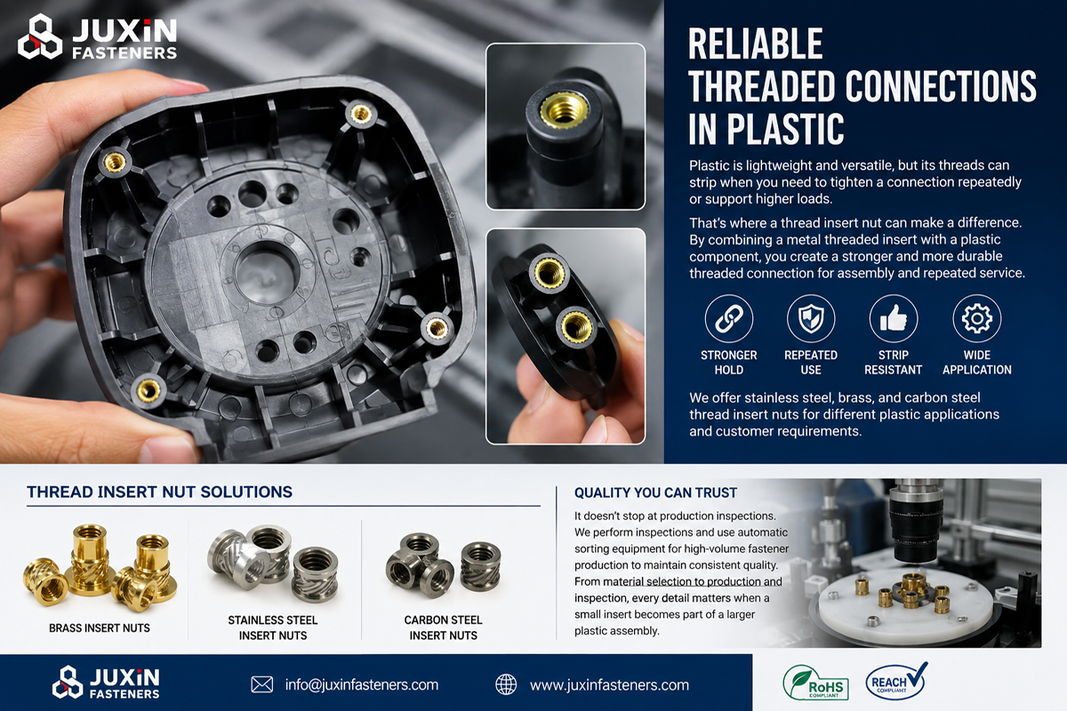
Heat set inserts for plastic create durable reusable metal threads inside thermoplastic components by using controlled heat to soften the polymer around a specially designed insert.
They are widely used when a molded plastic component requires a machine-thread interface capable of repeated assembly, maintenance,
or higher fastening loads than a direct thread in the polymer can reliably support.
Typical applications include electronic housings, automotive plastic components, electrical equipment,
telecommunications hardware, industrial controls, automation equipment, power electronics, instrumentation, and other engineered thermoplastic assemblies.
However, specifying a heat set insert involves much more than selecting an internal thread.
The reliability of the installed insert depends on the interaction between:
polymer type;
insert geometry;
knurl pattern;
insert length;
hole diameter;
molded boss geometry;
installation temperature;
insertion speed;
insertion depth;
plastic flow around the insert;
cooling conditions;
mating screw torque;
pull-out and torque-out requirements.
JUXIN FASTENERS supplies heat set inserts, threaded inserts for plastic, brass inserts, stainless steel inserts,
self-tapping inserts, and drawing-based threaded insert solutions for industrial OEM applications.
This guide explains how heat set inserts work, how to select them, why installations fail, and what engineering and procurement teams should specify before production sourcing.
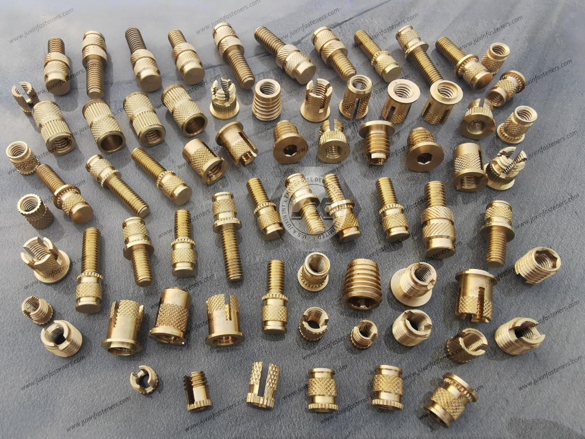
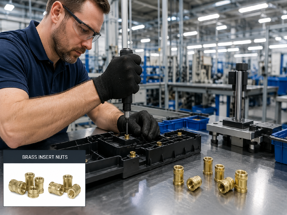
A heat set insert is a metal threaded insert designed to be thermally installed into a suitable thermoplastic component.
During installation, controlled heat is transferred from the installation equipment through the insert into the surrounding polymer.
The polymer immediately around the insert softens, allowing the insert to move into the prepared hole. Properly designed external features create spaces into which the softened polymer can flow.
When the assembly cools, the polymer solidifies around those features and mechanically retains the insert.
The internal machine thread then provides a reusable fastening point for a mating screw.
Common search terms include:
heat set inserts for plastic;
heat set threaded inserts;
brass heat set inserts;
brass threaded inserts;
threaded inserts for plastic;
plastic insert nuts;
metal inserts for plastic;
heat staking inserts;
threaded brass inserts;
thermoplastic threaded inserts.
These terms may describe overlapping product families, so an engineering drawing should ultimately define the required insert geometry rather than relying only on a generic product name.
Direct screw threads in plastic can be appropriate for many applications, particularly when the joint is lightly loaded and requires few assembly cycles.
A metal insert becomes more attractive when the design requires:
repeated assembly and disassembly;
a reusable machine thread;
controlled screw tightening;
greater resistance to thread wear;
improved load distribution into the plastic;
serviceability;
replacement of mating components without progressively damaging the polymer thread.
The engineering objective is not simply to make the thread “stronger.”
It is to create a predictable interface between a metal machine screw and a polymer component while managing the stresses transferred into the surrounding plastic.
A typical thermal insertion process follows this sequence:
A molded or machined receiving hole is prepared in the thermoplastic component.
The insert is positioned concentrically over the hole.
A heated installation tip contacts the insert.
Heat transfers into the insert and then into the surrounding polymer.
The polymer near the interface softens.
Controlled axial pressure moves the insert into position.
Softened polymer flows around the insert's knurls, grooves, undercuts, or other retention features.
The installation tool withdraws.
The polymer cools and solidifies around the insert.
The internal thread becomes the reusable fastening interface.
The quality of the joint depends heavily on what happens during Steps 4 through 9.
Too little heat may prevent sufficient polymer flow.
Too much heat can damage the boss, deform the component, or degrade the surrounding polymer.
Heat set insertion is therefore a controlled thermal assembly process rather than simply “pushing a hot insert into plastic.”
One of the first selection questions should be:
Can the parent polymer soften and reform appropriately under controlled heat?
Heat set insertion is primarily associated with thermoplastics because these materials can soften when heated and solidify again during cooling.
Potential parent materials can include suitable grades of:
ABS;
polycarbonate (PC);
polyamide/nylon (PA);
selected PC/ABS blends;
POM and other engineering thermoplastics where the process is validated;
selected high-performance thermoplastics.
Material grade matters.
For example, PA6, PA66, and glass-filled PA66 should not automatically be treated as identical materials for insert installation.
Fillers, fiber reinforcement, moisture condition, wall thickness, molding parameters, and polymer formulation can influence:
heat transfer;
material flow;
cracking behavior;
installation force;
retention performance.
Thermoset materials, highly brittle materials, and composites that do not respond appropriately to reheating may require another insert technology.
Brass is widely used for thermoplastic threaded inserts because it combines several useful manufacturing and installation characteristics.
Depending on the selected alloy and insert design, relevant characteristics can include:
good machinability;
effective heat transfer during thermal installation;
corrosion resistance appropriate to many indoor applications;
dimensional consistency;
ability to produce detailed knurl and retention geometries.
Efficient heat transfer is particularly useful because the insert must deliver controlled thermal energy to the polymer around the receiving hole.
However, brass should not be selected automatically for every application.
Insert material should also consider:
mechanical requirements;
corrosion environment;
electrical requirements;
operating temperature;
mating materials;
product weight;
customer specifications.
Stainless steel inserts may be considered when the application requires material characteristics different from those of brass.
Depending on product geometry and customer requirements, options may include stainless steel grades such as:
303;
304;
Potential reasons for selecting stainless steel include:
specific corrosion requirements;
mechanical requirements;
customer material specifications;
environmental compatibility.
However, thermal installation parameters may differ from brass because material properties and insert geometry influence heat transfer.
The installation process should therefore be validated for the actual insert material and polymer combination.
Stainless steel should also not be described as universally corrosion-proof.
Suitability depends on the specific grade, environment, mating materials, contaminants, temperature, and assembly geometry.
Steel inserts can be considered for suitable industrial plastic components where mechanical performance, cost, or customer specification supports their use.
Depending on the application, a protective finish may be specified.
The complete material system should be reviewed for:
corrosion;
coating compatibility;
installation temperature;
dimensional requirements;
electrical considerations;
service environment.
A heat set insert's outside surface is not merely decorative knurling.
Its geometry determines how softened polymer flows around the insert and how the installed component resists different loads.
Common external features may include:
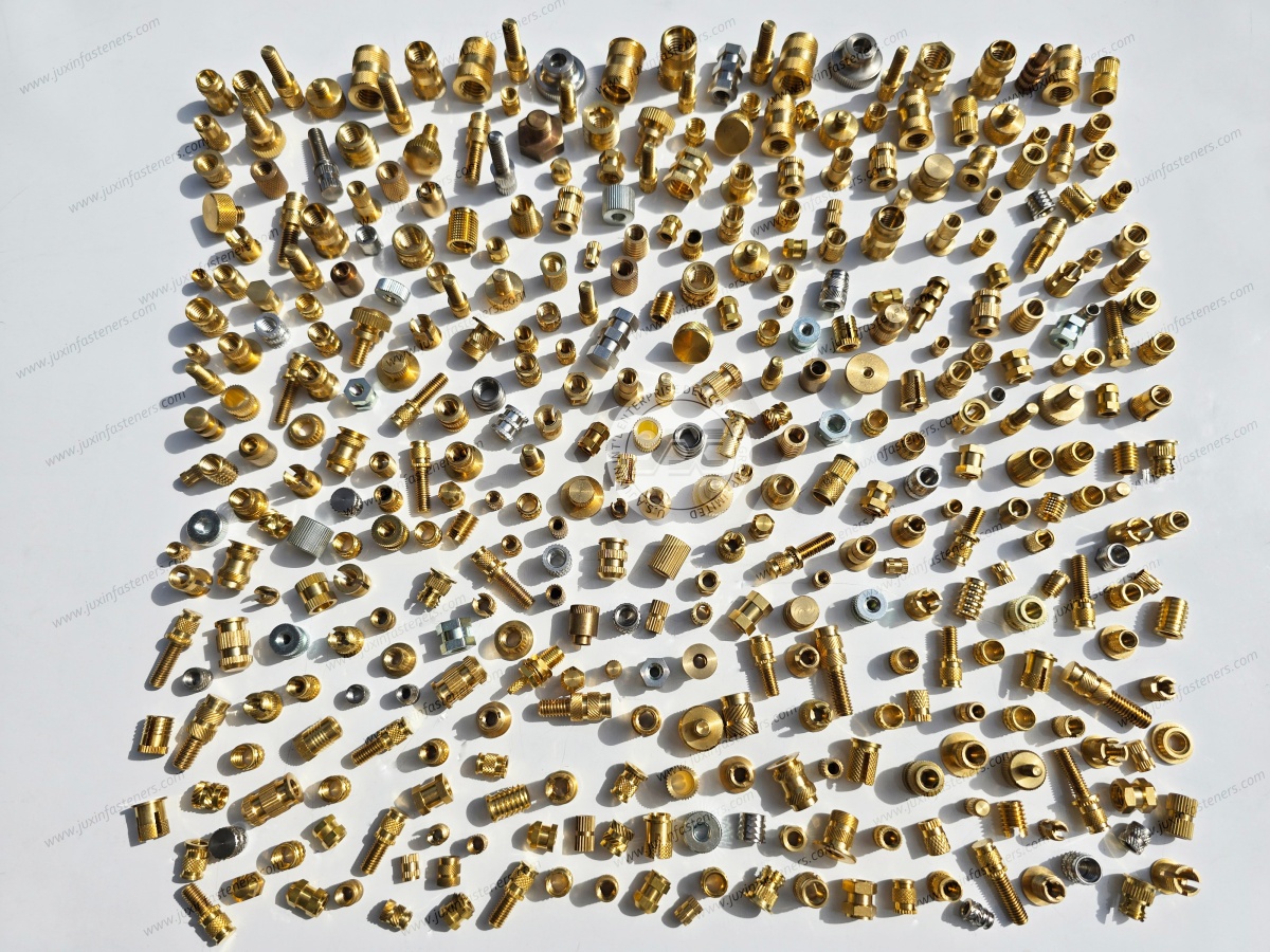
straight knurls;
diagonal knurls;
diamond-pattern knurls;
opposing knurl directions;
grooves;
undercuts;
tapered lead-in geometry.
Different features can contribute differently to axial and rotational retention.
The key engineering principle is:
Insert geometry should create a mechanical interlock with the resolidified polymer without generating excessive installation stress.
Heat set insert performance should not be reduced to a single statement such as “high strength.”
Two important failure modes are pull-out and torque-out.
Pull-out describes resistance to axial extraction of the insert from the plastic.
It can be influenced by:
insert length;
retention geometry;
hole diameter;
polymer strength;
boss geometry;
installation quality;
amount of polymer mechanically captured around the insert.
Torque-out describes resistance to rotation of the insert within the plastic.
It can be influenced by:
knurl geometry;
insert diameter;
polymer engagement;
installation quality;
hole geometry;
mating screw torque.
An insert design optimized for rotational resistance is not automatically optimized for axial extraction, and vice versa.
For critical applications, engineers should define the relevant mechanical requirement instead of specifying only “strong insert.”
One useful way to evaluate insert geometry is to ask which direction of movement the external features are intended to resist.
Axial extraction and rotational movement load the polymer differently.
Features that create strong circumferential mechanical interference can contribute to torque resistance, while grooves and undercuts that capture polymer axially can contribute to pull-out resistance.
Many engineered inserts therefore combine multiple retention features.
This is one reason two brass inserts with the same internal thread and similar overall dimensions may not provide equivalent performance.
When qualifying an alternative supplier, compare the complete outside geometry rather than only:
thread size;
insert length;
outside diameter.
Heat set inserts can use different body profiles.
A relatively straight body can provide controlled positioning where the receiving hole and installation process are designed for that geometry.
A tapered lead-in can help:
initial alignment;
entry into the receiving hole;
progressive polymer displacement.
However, “tapered” does not automatically mean better retention.
Retention depends on the complete geometry, polymer, hole, and installation process.
The component drawing and validation results should determine which configuration is appropriate.
The molded or machined receiving hole is one of the most important elements in a heat set insert joint.
If the hole is too small, excessive polymer displacement may occur.
Possible consequences include:
excessive insertion force;
boss swelling;
cracking;
surface distortion;
polymer accumulation;
insert misalignment.
If the hole is too large, insufficient polymer may engage the retention features.
Possible consequences include:
reduced torque-out resistance;
reduced pull-out resistance;
insert movement;
inconsistent positioning.
The optimum hole size therefore depends on:
insert geometry;
insert diameter;
polymer;
boss dimensions;
installation conditions.
Generic hole recommendations should be treated as a starting point and validated in the actual molded component.
A high-quality insert cannot compensate for inadequate plastic around the installation hole.
The molded boss must provide enough material to:
accept the displaced polymer;
resist radial installation stresses;
support service loads;
resist cracking;
maintain dimensional stability.
Engineers should evaluate:
boss outside diameter;
boss height;
surrounding wall thickness;
distance from edges;
nearby ribs;
molded-in stresses;
hole depth;
material flow during molding.
For compact plastic components, the limiting factor may therefore be the boss rather than the insert.
Blind-hole applications require sufficient depth beneath the final insert position.
If the insert bottoms mechanically before reaching the intended position, installation force can rise rapidly.
This may result in:
incomplete installation;
boss damage;
insert deformation;
incorrect installed depth.
Hole depth should therefore account for the complete insert geometry and installation process.
A common production mistake is assuming that increasing tool temperature always makes insertion easier.
Too little heat can cause:
inadequate polymer softening;
excessive insertion force;
poor material flow;
insert misalignment;
incomplete installation.
Too much heat can cause:
excessive melting;
boss deformation;
polymer degradation;
sink or cosmetic defects;
reduced dimensional control;
excessive material displacement.
The objective is controlled softening at the insert interface—not uncontrolled melting of the entire boss.
The appropriate process window depends on the polymer, insert material, insert mass, equipment, insertion speed, and component geometry.
Heat transfer requires time.
If the insert is driven too quickly, the polymer may not soften sufficiently before axial force is applied.
If installation is excessively slow, too much heat may spread into the surrounding component.
A stable process therefore balances:
Temperature + Contact Time + Insertion Speed + Axial Force + Final Depth
For high-volume OEM production, process repeatability is more important than simply achieving one successful installation.
After insertion, the polymer needs time to cool and regain sufficient stiffness around the insert.
Applying assembly torque while the surrounding plastic remains excessively soft can disturb the newly formed mechanical engagement.
Production sequencing should therefore consider cooling before the mating screw is fully assembled or mechanically loaded.
Understanding failure modes provides more engineering value than simply listing product benefits.
Possible causes include:
receiving hole too large;
insufficient polymer flow into the retention geometry;
incorrect insert geometry;
excessive mating screw torque;
poor thermal installation;
insufficient boss material.
Potential causes include:
insufficient engagement length;
inadequate undercut or retention geometry;
oversized hole;
weak parent polymer;
poor installation;
insufficient boss geometry;
service load above the validated condition.
Possible causes include:
hole too small;
insufficient boss diameter;
brittle or highly filled polymer;
excessive insertion force;
unsuitable insert geometry;
inadequate component design.
Possible causes include:
poor initial alignment;
uneven heat transfer;
unsuitable tooling;
excessive installation speed;
receiving-hole geometry.
Misalignment can create problems during mating screw assembly and may introduce unwanted stress.
Excessive polymer displacement may indicate:
undersized hole;
excessive insertion depth;
inappropriate geometry;
uncontrolled temperature or force.
Possible contributors include:
excessive temperature;
excessive axial force;
poor depth control;
insufficient support beneath the installation area.
These failure modes should be evaluated during sample qualification rather than after mass production begins.
Both processes use heat at the insert/polymer interface, but they generate it differently.
Heat is transferred from a controlled heated tool through the insert.
Advantages can include:
relatively simple process architecture;
controlled thermal input;
suitability for prototype through production applications;
good process visibility.
Ultrasonic energy generates localized heating at the interface as the insert is installed.
It can be useful in high-volume production when the insert, polymer, component geometry, tooling, and process are designed for ultrasonic installation.
The better process depends on:
polymer;
insert design;
cycle-time requirement;
equipment;
production volume;
component geometry;
process-control requirements.
Related Guide: Ultrasonic Threaded Inserts for Plastic Components
Mold-in inserts are positioned in the mold before polymer injection.
The plastic then forms around the insert during molding.
This can eliminate a secondary insertion operation, but it introduces other manufacturing considerations:
insert placement;
mold design;
insert retention during injection;
cycle time;
contamination control;
thread protection;
molding automation;
insert positional accuracy.
Mold-in installation should not automatically be described as stronger than post-mold heat insertion.
Performance depends on the insert geometry, polymer, molding process, component design, and loading.
For some high-volume components, mold-in insertion is advantageous. For other designs, post-mold insertion offers greater production flexibility.
Press-in inserts are mechanically installed without intentional thermal softening.
They can be appropriate when the polymer and insert geometry are designed for cold insertion.
However, cold pressing can generate higher mechanical stresses in the boss.
For brittle materials or compact bosses, this can increase cracking risk.
Selection should be based on:
Polymer Behavior → Insert Geometry → Boss Design → Assembly Equipment → Required Mechanical Performance
Self-tapping inserts establish external engagement mechanically rather than relying primarily on thermally softened polymer flow.
They may be considered when:
thermal installation is undesirable;
field installation is required;
the parent material supports self-tapping engagement;
a repair application is involved.
Heat set inserts may be preferred when:
the parent material is a suitable thermoplastic;
controlled thermal insertion is available;
molded boss geometry is optimized for the process;
high-volume repeatability is required.
Related Engineering Guide: Self Tapping Thread Inserts for Plastic and Aluminum
Direct screws into plastic remain useful in many products.
They may be appropriate when:
assembly cycles are limited;
loads are moderate;
service disassembly is unlikely;
component cost must be minimized;
the screw and boss are specifically designed for the polymer.
A threaded metal insert becomes more attractive when:
repeated service is expected;
a machine screw interface is required;
tightening must be more controlled;
direct plastic threads wear prematurely;
modular assembly is required.
The insert adds component and installation cost, so it should solve a real engineering requirement.
Not by themselves.
A properly installed insert provides a stable female thread within the plastic component.
Vibration loosening of the mating screw, however, depends on the complete bolted joint, including:
preload;
friction;
joint stiffness;
transverse movement;
bearing surfaces;
screw properties;
locking features;
assembly torque.
If vibration is critical, the complete fastening system should be validated under representative service conditions.
Plastic and metal typically respond differently to temperature changes.
In applications exposed to thermal cycling, engineers should consider:
polymer thermal expansion;
insert material;
boss geometry;
joint preload;
creep;
operating temperature;
repeated heating and cooling.
The insert may remain dimensionally stable while the surrounding polymer expands, contracts, or creeps.
This can influence long-term joint behavior even when the original installation is satisfactory.
A metal insert does not eliminate the time-dependent behavior of the surrounding polymer.
Under sustained load and elevated temperature, some plastics can creep.
Depending on the assembly architecture, creep may affect:
local boss geometry;
load distribution;
screw preload;
dimensional stability.
For long-life equipment, engineers should therefore evaluate the complete plastic joint rather than assuming the metal insert converts the assembly into a metal-to-metal fastening system.
Potential applications include:
electronic module housings;
interior plastic assemblies;
sensor housings;
control units;
thermal-management components;
electrical and electronic enclosures.
For automotive programs, the insert should be qualified according to the actual component drawing, polymer, service environment, loading, and customer requirements.
A general threaded insert should not automatically be described as automotive-qualified simply because it can be installed in an automotive component.
Potential applications include:
control housings;
converter and inverter enclosures;
electrical modules;
switchgear-related components;
power supply equipment;
thermal-management assemblies.
Depending on the design, engineers may also need to consider electrical conductivity, isolation, creepage and clearance, and grounding requirements.
Threaded inserts can be used in suitable:
communication equipment;
electronics housings;
server hardware;
control devices;
instrumentation;
network infrastructure components.
These applications often benefit from reusable threads where covers or modules require service access.
Applications can include:
plastic machine covers;
automation components;
robot peripheral equipment;
control systems;
instrumentation;
service panels.
Repeated maintenance can make durable metal threads particularly useful.
Heat set inserts may be used in appropriate plastic components for medical or laboratory equipment.
However, medical suitability depends on the complete product requirements, including materials,
cleaning, chemicals, sterilization conditions, documentation, and regulatory requirements where applicable.
The use of stainless steel or brass alone does not make an insert medically qualified.
High-performance thermoplastics such as PEEK may be candidates for threaded insert applications, but they should not be treated like commodity plastics.
Engineers should consider:
processing temperature;
service temperature;
insert material;
thermal installation capability;
polymer grade;
reinforcement;
boss geometry;
application load.
The installation process should be developed specifically for the actual polymer and component.
A useful selection process is:
Polymer → Assembly Cycles → Mechanical Load → Installation Method → Insert Geometry → Boss/Hole Design → Process Window → Validation
Example:
PA66 Housing → Repeated Service → M4 Machine Screw → Heat Installation → Knurled Brass Insert → Molded Boss
→ Controlled Temperature/Depth → Pull-Out and Torque-Out Validation
For another component:
Glass-Filled Polymer → High Rotational Load → Limited Boss Diameter → Candidate Insert Geometry → Hole Optimization → Sample Testing → Design Adjustment if Required
This approach is more reliable than selecting an insert only from a catalog thread-size table.
Depending on the application, the drawing or specification may define:
internal thread size;
thread pitch;
insert length;
insert outside diameter;
external knurl or retention geometry;
insert material;
finish where applicable;
receiving-hole diameter;
hole depth;
installed position;
parent polymer;
boss geometry;
pull-out requirement where specified;
torque-out requirement where specified;
inspection requirements.
For drawing-based custom inserts, a 2D drawing and 3D model can help define nonstandard geometry and assembly interfaces.
Relevant insert inspection points may include:
internal thread;
outside diameter;
overall length;
knurl geometry;
taper;
material;
finish;
visual condition.
Internal threads may be checked using appropriate GO/NO-GO thread gauges according to the specified thread system.
However, insert dimensional inspection is only one part of qualification.
The final installed performance also depends on the customer's:
polymer;
molded hole;
boss;
installation equipment;
thermal process.
For this reason, sample installation in representative components is particularly valuable.
For OEM programs, a practical qualification path can include:
Drawing review.
Material confirmation.
Sample production or sample selection.
Installation into representative customer components.
Installed-position inspection.
Customer-defined pull-out or torque-out testing where required.
Mating screw assembly evaluation.
Approval of the selected configuration.
Golden Sample or approved sample retention where required.
Transition to production control.
This reduces the risk of discovering polymer/insert incompatibility after production quantities have already been ordered.
For procurement development, strategic sourcing, commodity buyers, and supplier-development teams, the relevant sourcing question is not simply:
“What is the price of an M4 brass insert?”
Two M4 inserts may differ significantly in:
outside diameter;
length;
knurl pattern;
taper;
installation behavior;
parent-plastic compatibility;
mechanical retention.
Supplier evaluation should therefore consider:
drawing review;
dimensional capability;
internal thread inspection;
material specification;
sample qualification;
production consistency;
lot traceability where required;
packaging;
engineering change control;
documentation requirements;
prototype-to-production support.
When developing a second source, interchangeability should be confirmed through drawings and application validation rather than visual similarity.
For efficient engineering review and quotation, provide:
internal thread size;
thread pitch;
metric or Unified inch thread;
insert length;
outside diameter;
insert style or existing part number;
insert material;
surface finish if required;
plastic type;
polymer grade where known;
glass or other reinforcement content where applicable;
receiving-hole diameter;
hole depth;
boss dimensions where critical;
installation method;
required pull-out load if specified;
required torque-out value if specified;
operating temperature;
environmental requirements;
drawing;
2D or 3D file for custom parts;
sample quantity;
order quantity;
estimated annual demand;
documentation requirements;
traceability requirements;
packaging requirements.
For replacement or second-source projects, send the existing insert drawing whenever possible.
Heat set inserts are primarily intended for suitable thermoplastics. Actual compatibility depends on polymer grade, reinforcement,
boss geometry, insert design, and installation conditions.
Brass combines good machinability with useful heat-transfer characteristics for thermal insertion.
It also provides suitable corrosion performance for many applications. The final material choice should still match the operating environment.
During installation, softened polymer flows around the insert's knurls, grooves, undercuts, and other retention features.
After cooling, the solidified polymer mechanically engages those features.
There is no universal hole diameter for every insert and polymer. Hole size depends on insert geometry, parent material,
boss dimensions, and installation process. Supplier recommendations are a starting point and should be validated in the actual component.
Possible causes include an oversized receiving hole, insufficient polymer engagement, incorrect insert geometry,
inadequate thermal installation, insufficient boss material, or mating screw torque beyond the validated condition.
Potential causes include insufficient boss material, an undersized hole, a brittle or highly reinforced polymer, excessive insertion force, poor alignment, or unsuitable insert geometry.
Not necessarily. Installed position should be defined by the component design and insert geometry. Depending on the application, the insert may be flush or installed to a controlled depth below the surface.
Suitable stainless steel inserts can be thermally installed into appropriate thermoplastics, but the installation parameters may differ from brass.
The insert, polymer, tooling, and thermal process should be validated together.
Heat set insertion relies on controlled softening of the parent polymer.
Materials that do not respond appropriately to reheating may require press-in, self-tapping, molded-in, or another insert technology.
They can be used in appropriate applications, but glass-filled materials can behave differently from unfilled polymers.
Hole geometry, boss design, installation conditions, and mechanical performance should be validated using the actual material grade.
Heat set insertion transfers heat through a heated tool and insert. Ultrasonic insertion generates localized heat using high-frequency mechanical energy.
The preferred method depends on insert design, polymer, production equipment, cycle time, and component geometry.
No insert by itself guarantees resistance to vibration loosening. The mating screw joint must be designed for the required preload, movement, vibration, friction, and locking conditions.
Relevant internal links for this page should include:
Related Guide: Self Tapping Thread Inserts for Plastic and Aluminum
Related Guide: Tapping Inserts for Soft Metal
Related Guide: Ultrasonic Threaded Inserts for Plastic
Related Product: Brass Heat Set Inserts
Related Guide: Threaded Insert Selection for PA6 and PA66
Related Guide: Threaded Inserts for PEEK and High-Performance Plastics
Related Product: Plastic and Nylon Fasteners
Related Solution: Drawing-Based Custom Fasteners and CNC Machined Components
Use the existing indexed JUXIN FASTENERS URLs when implementing these internal links.
A reliable plastic threaded insert program starts with the polymer and assembly architecture—not simply with an internal thread size.
JUXIN FASTENERS supports industrial customers sourcing heat set inserts for plastic, brass threaded inserts,
stainless steel threaded inserts, self tapping inserts, and drawing-based insert components.
For engineering evaluation, provide the parent polymer, internal thread, receiving-hole dimensions,
boss geometry, insert material, installation process, operating environment, and required mechanical performance.
For procurement development, strategic sourcing, supplier qualification, and second-source programs, provide the existing drawing or specification,
sample quantity, production quantity, estimated annual demand, documentation requirements, inspection requirements, traceability requirements, and packaging requirements.
Where a custom insert is required, 2D drawings and 3D files can be reviewed against the intended plastic component and assembly conditions.
Email: info@juxinfasteners.com
Website: www.juxinfasteners.com
Contact Us
Tel.:
+86 020 8621 0320
+86 020 3121 6067
E-mail:
Technical Support:
Navigation
SEND INQUIREY