
Call Us
+86 136 6007 9809
Call Us
+86 136 6007 9809

Sep. 24, 2026
In high-volume electronics manufacturing, the fastener holding a printed circuit board may appear to be a minor component, but its influence extends far beyond its unit cost.
PCB mounting hardware affects assembly cycle time, operator handling, automation feasibility, board spacing, serviceability,
electrical isolation, vibration behavior, component clearance, enclosure design and total assembly cost.
Traditional threaded standoffs remain an effective solution when high mechanical retention, controlled threaded fastening or repeated service access is required.
However, every threaded mounting point introduces additional assembly operations: positioning the PCB, handling a screw, engaging the thread, driving the fastener and controlling the final assembly condition.
For OEMs and electronics manufacturing service providers producing large quantities of electronic assemblies, those operations accumulate across every board and every finished unit.
Snap-in standoffs, also called snap-fit PCB standoffs, snap-in circuit board standoffs, toolless PCB spacers, press-in board supports or quick-release PCB standoffs, provide a different mounting architecture.
Instead of relying on a separate screw at the PCB interface, the circuit board is pressed over an engineered snap feature.
The retention feature temporarily deflects during insertion and then recovers after passing through the PCB mounting hole, mechanically capturing the board.
The result can be a substantially simplified assembly process when the geometry, material, PCB hole, board thickness and required retention performance are correctly matched.
The engineering question, therefore, is not simply:
“Are snap-in standoffs better than threaded standoffs?”
A more useful question is:
“Which PCB mounting architecture provides the required retention, spacing, electrical behavior, serviceability and manufacturing throughput for this specific assembly?”
That distinction is important for design engineers, EMS process engineers and procurement teams evaluating board mounting hardware for AI server equipment,
telecommunications systems, automotive electronics, industrial automation, electrical enclosures, control systems and other high-volume electronic products.
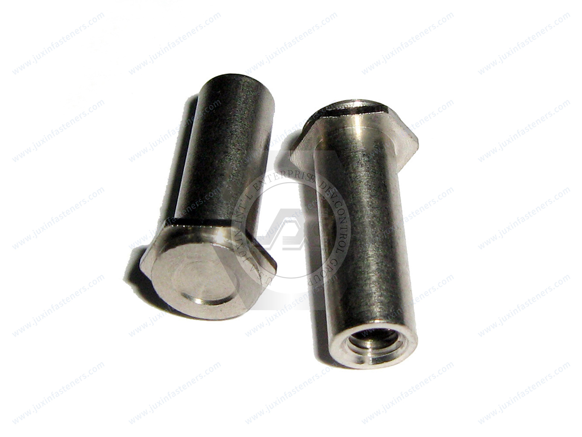
A snap-in standoff is a mechanical PCB support designed to establish a defined spacing distance while retaining the circuit board through a snap-fit or resilient engagement feature.
A typical configuration contains three functional zones:
PCB retention feature
The upper portion may use flexible barbs, split posts, arrowhead profiles, expandable fingers or another engineered snap geometry.
During installation, this feature compresses as it passes through the PCB mounting hole and then expands to capture the board.
Spacer body
The central body establishes the required distance between the PCB and the supporting chassis, panel or another circuit board.
This spacing can be critical for component clearance, airflow, creepage and clearance planning, connector alignment, wire routing and prevention of unintended contact with conductive enclosure surfaces.
Base attachment
The lower end connects the standoff to the supporting structure.
Depending on the product architecture, the base may use a self-clinching attachment, broaching feature, press-fit configuration, snap-in panel foot, threaded interface or another mechanical mounting method.
This creates an important sourcing distinction: the term snap-in standoff describes the PCB-retention function, but it does not by itself define how the opposite end attaches to the chassis.
OEM drawings should therefore specify both interfaces.
The snap feature functions through controlled elastic deflection.
During PCB installation, the board mounting hole is aligned with the standoff. As downward assembly force is applied, the retention feature deflects sufficiently to pass through the hole.
After the retaining geometry clears the board, the feature recovers toward its original shape. The resulting overlap between the retention feature and the PCB surface prevents unintended axial separation.
The spacer shoulder or body simultaneously establishes the designed board height.
This apparently simple mechanism depends on several interacting variables:
PCB mounting-hole diameter and tolerance
PCB thickness
retention-feature geometry
standoff material
material stiffness and elastic recovery
insertion force
extraction or pull-off requirement
board stiffness
local support around the mounting hole
operating temperature
vibration environment
required number and location of mounting points
expected installation and removal cycles
For this reason, snap-in PCB hardware should not be selected solely from a nominal screw or hole size.
The complete board-to-fastener interface must be evaluated.
Threaded and snap-in standoffs can perform the same fundamental spacing function, but they create very different manufacturing and service architectures.
| Engineering / Production Factor | Threaded Standoff | Snap-In Standoff |
|---|---|---|
| PCB retention | Screw-to-thread connection | Snap-fit mechanical engagement |
| Loose hardware | Usually requires a screw | May eliminate the PCB-side screw |
| Installation tools | Typically requires a driver | PCB interface may be assembled without a driver |
| Torque operation | Normally required | Normally not required at snap interface |
| Cross-threading risk | Must be controlled | Eliminated at non-threaded snap interface |
| Assembly process | Multiple fastening operations | Push-to-engage operation |
| Automation considerations | Screw feeding and driving may be required | Can simplify robotic or fixture-assisted pressing |
| Removal | Unscrew fastener | Depends on permanent or releasable snap design |
| Retention capability | Determined by thread, fastener and joint design | Determined by snap geometry, material and PCB interface |
| Electrical behavior | Depends on material and construction | Metal, polymer or hybrid configurations possible |
| Field servicing | Familiar and highly controllable | Can be very fast when releasable geometry is used |
| PCB hole design | Clearance hole for screw | Hole geometry becomes part of retention system |
The correct choice depends on the application rather than on one technology being universally superior.
A threaded standoff may be preferable when the assembly requires a defined threaded joint, high mechanical retention, conventional field servicing or a mounting architecture already qualified around screws.
A snap-in standoff becomes particularly attractive when assembly throughput, part-count reduction, toolless board installation and rapid service access are major design priorities.
In a conventional threaded PCB installation, the standoff itself is only one part of the assembly process.
The operator or automated station may also need to:
position the PCB;
handle individual screws;
align each screw with the threaded standoff;
start the thread correctly;
drive each screw;
control the assembly process;
verify completion;
manage dropped or missing hardware.
With snap-in board supports, several of these steps can potentially be eliminated.
The board can be aligned with multiple support posts and pressed into position until the snap features engage.
The actual cycle-time improvement varies significantly with board size, mounting-point count, operator method, automation level, accessibility,
fixture design and the threaded system being replaced. Therefore, a universal percentage or seconds-per-board claim is not technically appropriate.
The correct method is a time-motion comparison using the customer's real assembly.
For a sourcing or manufacturing engineering team, useful measurements include:
Current threaded assembly time per unit
Measure the actual time required to position the PCB, feed or pick screws, engage threads, drive each screw and complete inspection.
Snap-in installation time per unit
Measure PCB positioning, simultaneous or sequential snap engagement and any inspection step.
Defect opportunities
Compare dropped screws, cross-threading, damaged threads, incorrect torque, driver contact with PCB components and incomplete snap engagement.
Tooling requirements
Compare torque drivers, bits, screw feeders and maintenance requirements with any fixtures needed for snap assembly.
Service time
If field replacement matters, compare screw removal and reinstallation with the release method of the proposed snap-in design.
This process converts a fastener selection exercise into a measurable manufacturing-cost decision.
One of the most important differences between a snap-in standoff and a conventional screw-mounted PCB is the role of the circuit-board hole.
With a snap-fit design, the hole is not merely clearance for a screw.
It is a functional part of the retention system.
The relationship between the PCB hole and snap feature influences:
insertion force;
engagement depth;
retention force;
local PCB stress;
board deflection during installation;
ease of removal;
tolerance sensitivity.
An oversized hole may reduce the effective engagement of the retaining feature.
An undersized hole may increase insertion force and board stress or prevent complete engagement.
For that reason, a universal PCB-hole tolerance should not be applied to every snap-in standoff.
The required nominal diameter and tolerance depend on the specific retention geometry, PCB construction, board thickness, manufacturing process and required mechanical performance.
For many designs, a non-plated mounting hole may be used, but the required hole construction should be defined by the actual PCB and electrical design rather than assumed.
Design engineers should evaluate the standoff and PCB hole as a matched interface.
PCB thickness is another critical variable.
The distance between the standoff shoulder and the retaining feature must accommodate the actual board thickness and the desired installed condition.
If the grip geometry is too large relative to the board, excessive axial movement or board rattle may occur.
If the available grip is too small, the snap feature may not fully clear the board surface, preventing correct engagement or increasing installation stress.
Nominal PCB thickness alone may not be sufficient for supplier qualification.
For drawing-based sourcing, the engineering team should consider:
nominal PCB thickness;
PCB thickness tolerance;
local copper or coating conditions where relevant;
mounting-hole diameter;
mounting-hole tolerance;
required axial movement after installation;
allowable board deflection;
required insertion and removal behavior.
This is particularly important when qualifying a functional alternative to existing PCB hardware.
A visually similar snap standoff is not necessarily mechanically interchangeable.
The spacer-body height determines the distance between the PCB and the underlying panel, chassis or adjacent board.
That dimension can affect much more than mechanical packaging.
It may influence:
bottom-side component clearance;
airflow under the PCB;
heat dissipation;
connector engagement;
cable routing;
shielding architecture;
access for test probes;
creepage and clearance requirements;
alignment between stacked boards.
When replacing an existing PCB standoff with an alternative source, procurement teams should therefore avoid qualifying the component solely by overall appearance.
Installed board height is a functional dimension.
A small dimensional change may affect connector alignment or enclosure integration even when the standoff still fits the mounting holes.
One of the central engineering trade-offs in snap-in hardware is the relationship between assembly force and retention force.
Manufacturing teams generally want low insertion force because it improves ergonomics, reduces board flexing and simplifies automated installation.
Mechanical engineers generally want sufficient retention force to prevent unintended board release during handling, transportation, vibration and equipment operation.
Increasing barb engagement may increase retention but can also increase insertion force or PCB stress.
The objective is therefore not to maximize either value independently.
The goal is to establish an application-specific operating window:
Insertion force low enough for reliable production assembly
while maintaining
retention force high enough for the required mechanical environment.
Sample installation and mechanical validation are particularly valuable when changing supplier, material, PCB thickness or retention geometry.
Not all snap-in standoffs are designed for the same service strategy.
These designs prioritize resistance to unintended disengagement.
They may be appropriate for equipment in which the PCB is not expected to be removed regularly or where transportation and operational vibration require stronger retention.
Removal may require a tool, controlled barb compression or replacement of the fastener depending on the design.
These designs include retention features intended to be compressed, squeezed or otherwise released during servicing.
They can be useful in:
field-replaceable control boards;
telecommunications modules;
industrial controllers;
server subassemblies;
diagnostic equipment;
serviceable electronic enclosures.
The correct design should be selected according to both production assembly and maintenance strategy.
Fast installation alone does not determine the best product.
Metallic snap-in standoffs can be appropriate when the assembly requires structural rigidity, chassis attachment strength or an electrically conductive mechanical path.
Depending on the design, metal versions may combine a self-clinching, broaching, press-fit or other chassis-mounting base with a snap-retention feature for the circuit board.
Potential applications include:
server chassis;
telecommunications enclosures;
industrial control cabinets;
power electronics housings;
automation equipment;
metal instrumentation enclosures.
Material selection may include carbon steel, stainless steel, brass or other materials according to the design and environmental requirements.
Surface finish should be selected according to corrosion conditions, electrical requirements, appearance and compatibility with the mating materials.
Where grounding or electrical bonding is part of the design, conductivity should be validated as a system requirement rather than assumed merely because the fastener is metallic.
Polymeric snap-fit standoffs are widely considered where electrical isolation, low mass or non-conductive board support is required.
Depending on the application, engineering polymers may include nylon-based materials or higher-performance polymers.
However, the polymer name alone does not establish electrical, flammability or temperature performance.
For example, specifying “PA66” does not automatically mean that the finished component has a particular UL 94 classification.
Where the application requires a specific flammability rating, operating-temperature capability, dielectric property or material traceability,
those requirements should be stated explicitly in the drawing or RFQ and supported by the appropriate material documentation.
Non-metallic snap standoffs may be evaluated for:
power supplies;
electronic control modules;
display electronics;
instrumentation;
telecom electronics;
automotive electronic modules;
industrial controllers;
appliance electronics.
Some assemblies benefit from combining metal and polymer functions rather than selecting an entirely metallic or entirely polymeric standoff.
For example, a design may require strong attachment to a metal chassis while using a board-contact geometry selected for electrical isolation or controlled snap engagement.
Hybrid designs can help engineers balance:
chassis retention;
PCB protection;
electrical behavior;
assembly speed;
serviceability;
material compatibility.
Custom or drawing-based fasteners become particularly relevant when a standard catalog configuration cannot satisfy both chassis-side and PCB-side requirements.
Snap-in standoffs are frequently considered for equipment exposed to vibration, but “snap-in” does not automatically mean “vibration-proof.”
Retention performance depends on the complete assembly.
Engineers should evaluate:
snap-feature engagement;
number and location of support points;
PCB mass;
unsupported board span;
vibration direction;
acceleration environment;
operating temperature;
material creep or relaxation;
chassis stiffness;
board thickness;
repeated loading.
In automotive electronics, transportation equipment, industrial machinery and other dynamic applications, the actual assembly may require vibration validation before production approval.
The relevant acceptance criteria should come from the OEM's product-level engineering requirements.

Modern AI computing and server systems contain far more than a single motherboard.
High-density equipment may include secondary monitoring cards, fan-control boards, power-management boards,
LED indicator modules, networking boards and other electronic subassemblies distributed throughout the chassis.
Potential snap-in standoff applications include:
GPU server sub-card supports;
fan-tray control boards;
power-shelf monitoring modules;
front-panel indicator boards;
network equipment control cards;
cooling-system control electronics;
auxiliary sensor boards.
Toolless PCB mounting can be particularly useful where assembly access is restricted or where large numbers of secondary boards must be installed across high-volume equipment.
The design team should still verify thermal environment, airflow, service access and required retention before replacing threaded hardware.
Electronic content continues to expand across vehicle platforms.
Possible applications for snap-fit PCB supports include:
digital cockpit electronics;
infotainment controller boards;
instrument-cluster modules;
lighting control electronics;
battery monitoring subassemblies;
sensor modules;
antenna electronics;
other interior electronic modules.
For these applications, material selection and mechanical retention require careful evaluation because the assembly may experience vibration, temperature cycling and long service periods.
Where electrical isolation is required, polymeric hardware may be considered, but the actual dielectric, temperature and flammability requirements should be specified by the vehicle or module engineering team.
Telecommunications equipment frequently combines dense PCB packaging with serviceability requirements.
Snap-in circuit board standoffs may support:
network-switch sub-boards;
communications cards;
power-distribution electronics;
indicator boards;
control cards;
rack-mounted telecom modules.
A releasable snap configuration can reduce service operations where boards must be removed without repeatedly handling several small screws.
For procurement teams, maintaining consistent hole fit and retention behavior across production lots is essential because dimensional variation can directly affect assembly-line performance.
EMS manufacturers evaluate hardware not only by piece price but also by how it affects production.
A lower-cost component can become expensive if it increases:
operator handling;
assembly time;
rework;
inspection;
tooling maintenance;
dropped-part incidents;
line interruptions.
Conversely, a snap-in standoff may justify a different unit cost if it eliminates loose screws and simplifies the assembly operation.
The appropriate sourcing comparison is therefore:
component cost + installation cost + defect risk + tooling cost + service impact
rather than component price alone.
This total-assembly-cost approach is especially relevant for high-volume products.
Industrial control systems frequently contain PLC boards, I/O modules, communication boards, power electronics and display interfaces.
Possible applications include:
PLC expansion boards;
robot controller electronics;
machine-vision control modules;
inverter control boards;
industrial HMI electronics;
sensor-interface boards;
automated equipment control cards.
Snap-fit PCB supports can simplify assembly where rapid production and controlled board spacing are priorities.
Where equipment operates near motors, drives or power electronics, the electrical and thermal environment should be considered during material selection.
Compact electrical equipment often contains stacked PCBs or display-to-mainboard assemblies.
Potential applications include:
smart electricity meters;
measurement instruments;
commercial HVAC controllers;
thermostats;
monitoring devices;
electrical control equipment.
Snap-in spacers can reduce hardware count while maintaining board separation.
For stacked assemblies, standoff height and connector alignment should be controlled carefully because accumulated dimensional variation may affect mating connectors or enclosure fit.
Medical and precision electronic equipment may use PCB standoffs where compact packaging, controlled spacing and service access are required.
The hardware itself should not be assumed to satisfy any medical-device requirement merely because it is used in a medical assembly.
Material, cleanliness, traceability, environmental and regulatory requirements must be defined by the specific OEM application.
This distinction is important when sourcing custom PCB hardware for regulated industries.
Toolless assembly is attractive, but snap-in hardware should not automatically replace every threaded standoff.
Threaded mounting may remain preferable when:
the joint requires a defined threaded fastening system;
high retention capacity is required;
the PCB is heavy;
large external connectors apply significant forces to the board;
field technicians expect conventional screw servicing;
repeated disassembly is required;
existing qualification is based on threaded hardware;
the enclosure architecture does not provide an appropriate snap-fit hole;
board material or thickness is unsuitable for the proposed retention geometry.
A strong engineering decision considers the complete product lifecycle rather than assembly speed alone.
Procurement teams frequently need a second source for existing PCB hardware.
This may be driven by:
supply-chain risk reduction;
cost optimization;
lead-time requirements;
regional sourcing;
product lifecycle management;
supplier consolidation;
capacity planning.
A functional equivalent should not be approved simply because its catalog dimensions appear similar.
The qualification process should compare the original component and candidate alternative across the actual functional interfaces.
Verify:
PCB hole diameter;
hole tolerance;
board thickness;
snap geometry;
installed engagement;
insertion behavior;
extraction or retention requirement.
Verify:
chassis hole size;
panel thickness;
base mounting method;
installed retention;
surrounding sheet-metal geometry.
Verify:
standoff height;
shoulder geometry;
PCB-to-chassis spacing;
connector alignment;
adjacent component clearance.
Verify:
base material;
polymer grade where applicable;
surface finish;
corrosion requirement;
electrical requirements;
temperature requirements;
flammability requirement where specified.
Validate candidate samples in the customer's actual or representative assembly.
The purpose is not simply to determine whether the component can be installed.
The objective is to verify whether it performs the required function throughout manufacturing and service.
For new snap-in standoff programs or second-source qualification, physical sample validation can reveal issues that dimensional comparison alone may miss.
A practical evaluation may include:
Installation trial
Confirm that the board can be installed without excessive force, unintended bending or damage.
Retention evaluation
Verify that the board remains captured under the application's defined loading conditions.
Removal trial
For releasable designs, verify that technicians can remove the PCB without damaging the laminate, mounting hole or retention feature.
Dimensional verification
Confirm installed board height and connector alignment.
Environmental evaluation
Where required by the application, assess performance after relevant temperature, vibration or other environmental exposure.
Acceptance criteria should be established by the OEM or engineering organization responsible for the final assembly.
A strategic sourcing team evaluating snap-in standoffs should go beyond requesting a unit price.
Important questions include:
Can the supplier manufacture the required retention geometry consistently?
Can PCB and chassis interfaces be reviewed against the customer's drawing?
What material options are available?
Can material documentation be provided when required?
Can custom standoff heights or snap geometries be produced?
Can prototype or engineering samples be supplied?
How will critical dimensions be controlled?
Can the supplier support annual production volume?
Are surface finishes available for the specified environmental conditions?
Can a functional alternative be developed from an existing drawing or physical sample?
What packaging method is appropriate for automated or manual assembly?
These questions help procurement distinguish a simple catalog seller from a supplier capable of supporting an engineered OEM program.
A complete RFQ reduces clarification cycles and improves quotation accuracy.
For a new or custom snap-in standoff project, provide as much of the following information as possible:
Engineering drawing
A 2D drawing is particularly useful for defining critical interfaces. A 3D model can supplement the drawing when the geometry is complex.
PCB information
Include:
PCB mounting-hole diameter;
hole tolerance;
PCB thickness;
thickness tolerance;
board material where relevant;
plated or non-plated hole requirement where applicable.
Chassis information
Include:
chassis mounting-hole dimensions;
panel thickness;
panel material;
required base attachment method.
Standoff geometry
Define:
installed board spacing;
overall height;
shoulder dimensions;
snap retention style;
permanent or releasable requirement.
Mechanical requirements
Where relevant, provide:
insertion-force requirement;
retention or pull-off requirement;
vibration conditions;
expected removal cycles;
board mass;
external loads applied through connectors or cables.
Material requirements
Specify:
metal or polymer preference;
required material grade;
electrical-isolation requirements;
temperature requirements;
flammability classification if required;
corrosion or finish requirements.
Commercial information
Provide:
sample quantity;
prototype quantity;
pilot-run quantity;
estimated annual usage;
target production timing;
packaging requirements.
This information allows engineering and sourcing teams to evaluate the component as part of the actual assembly rather than as an isolated fastener.
Standard snap-in standoffs can be appropriate when the customer's board thickness, hole size, spacer height and chassis interface match an existing configuration.
Custom hardware becomes relevant when the application requires:
a special board hole;
non-standard board thickness;
unique spacer height;
modified retention force;
restricted installation envelope;
special chassis attachment;
unusual material;
special corrosion protection;
controlled electrical characteristics;
specific service-release behavior.
Custom fastener development should begin from the functional interfaces and operating conditions rather than from appearance alone.
For an OEM program, the customer's drawing is the primary engineering communication document.
Snap-in standoffs are part of a broader engineered fastening architecture used in electronic enclosures and sheet-metal assemblies.
Design and procurement teams evaluating PCB hardware may also need to compare:
Broaching Fasteners
Useful for creating durable threaded or standoff features in PCBs and other thin or non-ductile materials when a threaded connection is preferred.
Self-Clinching Fasteners
Used to create permanent nuts, studs and standoffs in suitable sheet-metal panels.
Keyhole Standoffs
Can support rapid panel or board engagement where the assembly geometry is designed around keyhole-style attachment.
Captive Panel Screws
Useful when access panels require repeated servicing while preventing loose screws from being separated from the assembly.
Floating Self-Clinching Nuts
Can provide thread-location accommodation where mating-hole alignment requires controlled float.
Custom Metal Panel Fasteners
Useful when standard hardware cannot satisfy the required chassis, board, clearance or installation geometry.
These technologies should not be treated as interchangeable. Each solves a different combination of assembly, retention, service and tolerance problems.
For a new design, engineers can evaluate the decision through several questions.
Is production throughput a major cost driver?
If yes, reducing individual screwdriving operations may justify evaluating snap-in hardware.
Does the PCB require very high retention or carry significant external loads?
If yes, threaded mounting or another reinforced retention architecture may be more appropriate.
Does the board require rapid service replacement?
A releasable snap design may reduce service time, but the release mechanism must be accessible.
Is electrical isolation required?
Polymeric hardware may be considered, provided the specified material properties are verified.
Is grounding required through the mounting hardware?
A suitable conductive architecture may be required, and electrical performance should be validated.
Is the PCB hole already fixed by an existing design?
The candidate snap geometry must be qualified against the existing hole rather than forcing a catalog assumption onto the PCB.
Will the assembly experience significant vibration or temperature variation?
Retention and material behavior should be validated under the application's actual requirements.
This framework helps prevent the common mistake of selecting PCB mounting hardware from catalog dimensions without considering the complete assembly.
For sourcing teams, one of the most important insights is that PCB mounting hardware should not be evaluated only as a purchased component.
A standoff also defines part of the factory process.
Changing from threaded to snap-in mounting can affect:
assembly station design;
operator motions;
screw feeders;
torque equipment;
robotic programming;
inspection procedures;
defect modes;
service procedures;
component count;
inventory complexity.
That means a slightly different fastener architecture can create savings or costs far beyond the purchase price of the component itself.
For high-volume OEM and EMS programs, the correct commercial comparison is therefore based on total installed cost and process performance, not simply price per piece.
Another common sourcing mistake is requesting the “highest possible pull-out force.”
Higher retention is not automatically better.
A more aggressive snap geometry can increase insertion force and local stress around the PCB mounting hole.
For thin boards, sensitive laminates or large unsupported spans, excessive installation force may cause undesirable board flexing.
The better specification defines a balanced window:
acceptable installation force;
required minimum retention;
allowable PCB deflection;
service-removal requirement;
environmental loading.
This creates a more useful engineering target for both the fastener manufacturer and the OEM.
For supply-chain teams, functional equivalence is not established by matching only outer dimensions.
A second-source snap-in standoff must preserve the functional relationships between:
fastener and PCB
fastener and chassis
PCB and enclosure
PCB and connectors
PCB and neighboring components
This is why drawing review, samples and assembly validation are important before approving a substitute.
A dimensional cross-reference can start the qualification process.
It should not automatically finish it.
JUXIN FASTENERS supports OEM and industrial customers sourcing snap-in standoffs, snap-fit PCB spacers, circuit board supports, engineered panel fasteners and custom PCB mounting hardware.
Projects can begin from:
customer 2D drawings;
3D models;
existing part specifications;
physical samples;
dimensional requirements;
functional-equivalent sourcing requirements.
For custom or alternative-source programs, the engineering review should focus on the complete interface: PCB hole, board thickness,
chassis geometry, standoff height, retention feature, material, installation behavior and required operating environment.
Samples can then be evaluated in the customer's actual assembly before production approval.
This approach is particularly valuable for OEMs, EMS manufacturers, electronics enclosure producers and strategic sourcing teams that need to reduce assembly complexity,
qualify a second source or develop board-mounting hardware around a new product architecture.
For an efficient technical review, send the available drawing or component specification together with the PCB and chassis interface information.
A useful RFQ package should include:
2D drawing and/or 3D model;
PCB hole diameter and tolerance;
PCB thickness and tolerance;
chassis hole and panel thickness;
required standoff height;
base attachment method;
permanent or releasable retention requirement;
material requirements;
environmental requirements;
specified flammability requirement where applicable;
insertion or retention requirements where defined;
sample quantity;
estimated annual usage;
production schedule.
The objective is to move directly from engineering definition → sample validation → supplier qualification → volume production,
reducing unnecessary quotation cycles and avoiding incorrect assumptions about board fit.
For technical drawing reviews, sample requests, custom snap-in standoffs, functional-equivalent PCB hardware or volume quotations, contact JUXIN FASTENERS.
Email: info@juxinfasteners.com
Website: www.juxinfasteners.com

 MORE NEWS
Sep. 24, 2026
Sep. 24, 2026
Sep. 22, 2026
Contact Us
Tel.:
+86 020 8621 0320
+86 020 3121 6067
E-mail:
Technical Support:
Navigation
SEND INQUIREY