
Call Us
+86 136 6007 9809
Call Us
+86 136 6007 9809

Sep. 22, 2026
A clip-on nut may appear to be a simple component, but a reliable OEM specification requires more than a thread size and a photograph.
U-nuts, J-nuts, barrel clip nuts, enclosed threaded clips, tapping-screw clips, and custom spring fasteners interact directly with the customer’s sheet-metal edge,
panel thickness, hole location, mating screw, coating, installation process, and operating environment.
If an engineering drawing or RFQ omits one of these interfaces, two fasteners that appear similar may behave very differently in production.
An incomplete specification can lead to:
Incorrect panel grip
Excessive installation force
Insufficient clip retention
Hole-to-thread misalignment
Cross-threading
Screw binding
Low strip torque
Clip rotation or migration
Coating damage
Corrosion failure
Automated feeding problems
Assembly-line rework
Delayed sample approval
Incorrect supplier quotations
Uncontrolled part substitutions
A complete clip-on nut RFQ allows design engineers, procurement teams, supplier quality engineers,
and fastener manufacturers to evaluate the same functional requirements before tooling, sampling, or production begins.
At minimum, a clip-on nut RFQ should identify:
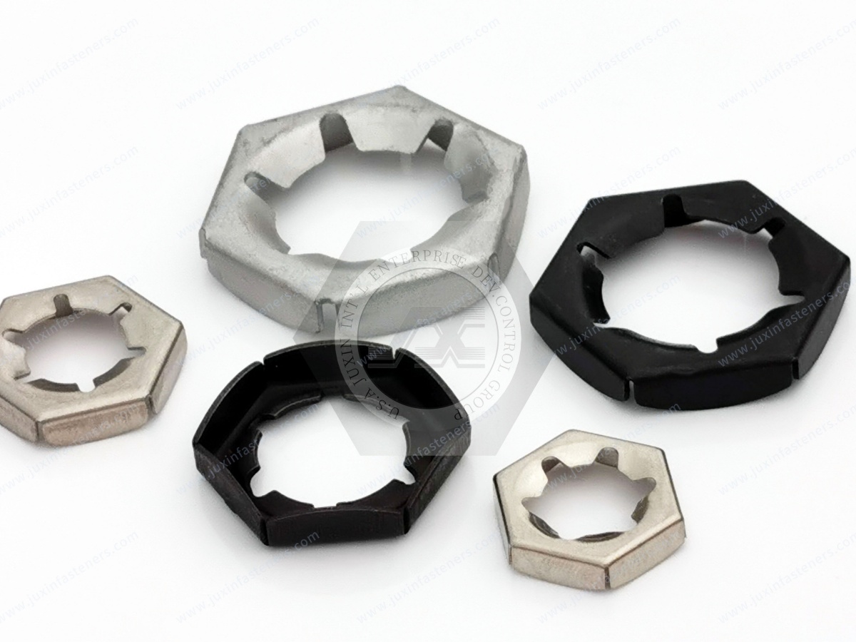
Fastener type
Metric or inch thread
Mating screw specification
Panel material
Minimum and maximum panel thickness
Panel-hole diameter
Hole setback from the panel edge
Flange geometry and bend radius
Fastener material and hardness
Surface finish
Installation direction
Installation-force requirement
Retention-force requirement
Target tightening torque
Minimum strip or failure torque
Corrosion requirement
Validation and documentation requirements
Prototype quantity
Annual production volume
Delivery and packaging requirements
For custom components, provide a controlled 2D drawing and the mating-panel geometry.
A 3D model is valuable for spatial review but does not replace a drawing that defines tolerances, material, finish, thread, performance, and inspection requirements.
An inquiry requesting only an “M6 U-nut” leaves critical questions unanswered.
The supplier still does not know:
Whether the thread is M6 × 1.0 or another pitch
Which thread tolerance is required
What panel thickness the clip must fit
Whether the panel is coated
How far the hole is positioned from the edge
Whether the thread must float
Which screw will be installed
What installation torque will be used
Whether the clip is installed manually or automatically
Which material and coating are required
What corrosion performance is expected
Whether repeated service access is required
Whether the fastener is standard or custom
What annual volume supports the project
Quoting from incomplete information increases the risk of comparing technically different products on unit price alone.
The RFQ should state the required product type or describe the function clearly enough for the supplier to recommend one.
Common categories include:
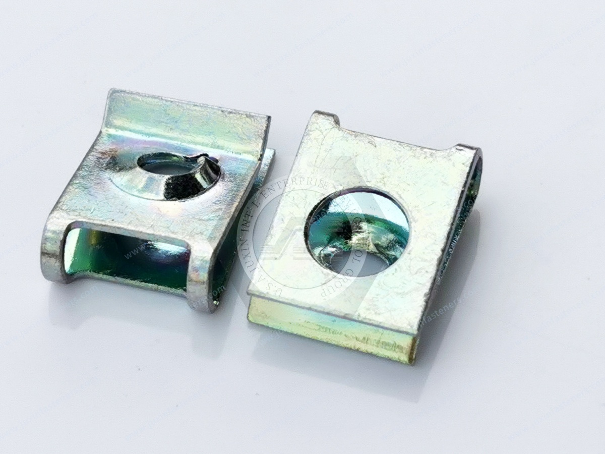
U-nuts generally wrap around a panel edge and provide a threaded feature aligned with a clearance hole. They are often selected where the screw axis is positioned within a relatively symmetrical clip geometry.
J-nuts use an offset geometry that can suit asymmetric panel layouts, restricted access, or a thread position that is not centered within a conventional U-shaped profile.
Barrel-type clip nuts may provide an enclosed or supported threaded feature with controlled alignment and stronger resistance to rotation.
These fasteners retain a separate or integrated threaded element inside a spring clip and may be appropriate where a full internal thread form or limited float is required.
These clips are designed for compatible thread-forming or tapping screws rather than a conventional machine-screw thread.
Custom development may be justified when standard throat depth, panel range, overall size, thread location, retention force, or installation envelope cannot meet the application.
For geometry selection, review U-Nuts vs J-Nuts.
The mating sheet metal is part of the fastening system. A supplier cannot validate clip fit without understanding it.
The RFQ should specify:
Panel material
Nominal thickness
Minimum thickness
Maximum thickness
Coating type
Coating thickness where functionally significant
Number of material layers
Flat, bent, hemmed, or returned edge
Flange width
Bend radius
Bend angle
Edge condition
Burr direction and limit where critical
Hole diameter
Hole shape
Hole-position tolerance
Hole setback
Distance from the hole to the bend tangent
Nearby ribs, embossments, seals, or obstructions
A nominal thickness such as 1.0 mm does not define the actual minimum and maximum condition.
Clip fit can also change after:
Powder coating
E-coating
Paint
Plating
Anodizing
Lamination
Addition of a washer or gasket
Assembly of multiple sheet layers
The drawing should clarify whether thickness dimensions refer to bare metal or the final coated assembly.
See the Clip-On Nut Panel Thickness Selection Guide for additional grip-range considerations.
The clip’s throat depth must align its threaded feature with the panel clearance hole.
The drawing should identify:
Functional panel edge
Distance from that edge to the hole centerline
Hole diameter
Positional tolerance
Flange width
Bend location
Bend radius
Available flat seating area
A photograph may show the general arrangement but cannot reliably define these relationships.
Incorrect setback may cause:
Screw interference with the panel hole
Angular thread engagement
Cross-threading
Incomplete clip seating
Edge deformation
Clip migration
Reduced torque capacity
For calculation and tolerance guidance, review Edge Distance and Hole Setback Engineering.
The drawing should dimension critical features from the surfaces that actually locate the clip in assembly.
Possible functional datums include:
Panel free edge
Primary panel surface
Clearance-hole axis
Formed flange surface
Bend tangent
Mating screw axis
Dimensioning the hole from an unrelated exterior feature can create unnecessary tolerance accumulation.
ISO 1101 or ASME Y14.5 principles may be used to communicate:
Position
Profile
Perpendicularity
Parallelism
Flatness
Orientation
Datum relationships
The drawing should use one clearly identified tolerancing framework. Mixing symbols or assumptions from different systems without explanation can create inspection disputes.
A thread designation must include more than nominal diameter.
A metric thread specification should identify:
Nominal diameter
Pitch
Internal thread tolerance
Mating external thread tolerance
Required engagement
Gaging requirement
Coating allowance
Example structure:
M6 × 1.0 – internal tolerance as specified on the controlled drawing
The final tolerance should be selected according to the applicable ISO metric thread framework and the customer’s mating screw.
An inch-thread specification should identify:
Nominal diameter
Threads per inch
UNC, UNF, or other approved series
Internal thread class
Mating external thread class
Gaging requirement
Coating allowance
Example structure:
1/4-20 UNC – internal thread class as specified on the controlled drawing
ASME B1.1 applies to UN, UNR, and UNJ thread forms. The actual thread class and inspection requirement must be stated.
The RFQ should identify:
Screw manufacturer or standard
Major diameter
Thread profile
Pitch
Point style
Material
Hardness
Surface finish
Installation speed
Target torque
Reuse requirement
A clip developed for one thread-forming screw should not be assumed compatible with every screw of similar diameter.
For further guidance, see Screw Compatibility and Thread Engagement.
The screw and clip must be specified as a system.
Provide:
Screw standard or controlled drawing
Diameter
Pitch or thread series
Length
Head style
Drive style
Strength class or grade
Material
Surface finish
Thread-forming or machine-screw designation
Installation torque
Installation speed
Driver type
Manual or automated installation
Reuse requirement
A harder or stronger screw can strip a weak clip thread if the torque-control strategy is incorrect. A heavily coated screw may also affect thread fit and installation friction.
For a custom or tightly controlled clip-on nut, the drawing may need to define:
Overall length
Overall width
Overall height
Material thickness
Throat depth
Clip opening
Spring-leg spacing
Entry angle
Bend radii
Thread-center position
Clearance-hole position
Floating-thread travel
Anti-rotation features
Locating lances
Panel contact points
Burr direction
Edge condition
Permitted distortion
Installation orientation
Not every dimension requires an unnecessarily tight tolerance. Critical dimensions should be tied to function, inspection capability, and production feasibility.
Over-tolerancing increases tooling, inspection, and production cost without necessarily improving assembly performance.
The material requirement should support the required spring behavior, forming process, corrosion resistance, and operating environment.
Possible categories include:
Carbon spring steel
Alloy spring steel
Stainless spring steel
Customer-approved specialty alloy
The drawing or purchase specification should identify:
Applicable international material designation
Material condition
Strip thickness
Thickness tolerance
Final hardness or mechanical-property range
Heat-treatment requirement
Decarburization limits where relevant
Surface-condition requirements
Material certification requirements
Material substitutions should not be approved based solely on a claimed “equivalent” grade. Chemistry, mechanical properties,
hardenability, formability, spring behavior, corrosion performance, and heat treatment must be reviewed.
Spring fasteners depend on controlled elasticity and recovery.
The specification should state:
Final hardness range
Test method
Measurement location where necessary
Heat-treatment requirement
Tempering requirement
Distortion limits
Decarburization requirement where applicable
Batch traceability
Required heat-treatment records
Excessive hardness may increase brittleness and hydrogen susceptibility. Insufficient hardness may reduce retention, permit permanent deformation, or cause loss of spring force.
The optimum condition is the hardness range validated for the actual geometry and application—not simply the highest achievable hardness.
A coating callout should identify more than color.
Specify:
Coating type
Applicable standard
Minimum or controlled coating thickness
Conversion coating or topcoat
Color where required
Corrosion-test method
Exposure duration and acceptance criteria
Thread-fit requirement after coating
Friction requirement where applicable
Electrical conductivity or grounding requirement
Cosmetic requirements
Restricted-substances requirements
Hydrogen-embrittlement controls where applicable
Possible systems may include:
Electroplated zinc
Zinc-alloy electroplating
Zinc-flake coating
Mechanical deposition
Phosphate-based finish
Organic topcoat
Stainless spring material without an added metallic coating
Salt-spray duration alone does not fully define service performance. Real-world corrosion also depends on coating damage, geometry, drainage, galvanic combinations, chemicals, temperature, and maintenance.
Hardened spring steels exposed to acid cleaning, electroplating, stripping, or other hydrogen-generating processes may require specific controls.
The RFQ should define, where applicable:
Governing hydrogen-control standard
Maximum hardness subject to special control
Permitted cleaning and coating routes
Maximum delay before relief treatment
Approved baking procedure
Process-control testing
Lot traceability
Required records
Restrictions on stripping and replating
Batch-release evidence
A generic statement such as “bake after plating” does not fully define the required process.
For detailed guidance, see Hydrogen Embrittlement Mitigation in High-Strength Spring Steel Fasteners.
Installation force controls whether the clip can be assembled safely and repeatably.
Define:
Minimum installation force where accidental loose fit is a concern
Maximum installation force
Test panel material
Test panel thickness
Coating condition
Installation direction
Installation speed
Test fixture
Number of samples
Acceptance criteria
A clip that provides high retention may still be unsuitable if it requires excessive manual force or causes automated installation jams.
Retention force measures how well the unloaded clip remains attached before the screw creates the final joint.
The specification should define:
Pull-off direction
Push-off or displacement direction
Panel thickness
Panel material
Coating
Installation depth
Test speed
Minimum force
Maximum force where removal is required
Number of installation cycles
Sample size
Retention force should not be confused with the structural strength of the completed screw joint.
The RFQ should distinguish between:
The torque used in the customer’s assembly process.
Resistance encountered before the joint is fully seated, where applicable.
The torque at which the clip thread, screw thread, panel interface, or clip geometry loses the ability to carry additional tightening load.
The torque at which another defined failure occurs, such as clip rotation, thread pullout, fracture, or permanent deformation.
The specification should define:
Mating screw
Screw condition
Panel
Hole geometry
Installation speed
Lubrication or coating
Tool type
Torque rate
Failure definition
Required margin above installation torque
Sample size
Retest rules
An undefined request for “high torque” cannot be validated consistently.
Where the clip supports a functional load, specify:
Tensile load
Shear load
Combined load
Load direction
Static or cyclic loading
Test fixture
Panel configuration
Screw preload
Temperature
Acceptance criteria
Permanent-deformation limit
The completed joint includes the screw, clip, panel, hole, coating, and applied clamp load. Testing the clip alone may not represent the assembled system.
Applications in vehicles, rail equipment, industrial machinery, compressors, HVAC systems, robotics, and automated equipment may require dynamic validation.
The RFQ should define:
Vibration profile
Frequency range
Acceleration
Duration
Mounting orientation
Temperature
Applied joint load
Screw torque
Permitted movement
Retention criteria
Post-test inspection
Avoid writing only “vibration resistant.” That phrase does not establish a reproducible test.
Provide the actual operating conditions:
Minimum temperature
Maximum temperature
Thermal-cycle range
Number of cycles
Humidity
Water exposure
Salt-containing environment
Cleaning chemicals
Oils or coolants
Outdoor exposure
UV exposure where packaging or polymer components are involved
Electrical or grounding requirements
Cleanliness requirements
A corrosion-resistant material or coating must be selected for the real environment rather than for a generic industry label.
Access panels and maintenance covers may be removed repeatedly.
Specify:
Number of screw-removal cycles
Whether the clip may be removed from the panel
Permitted loss of retention
Thread-damage criteria
Coating-damage criteria
Screw replacement interval
Field-service tool
Accessibility constraints
A fastener suitable for one-time factory assembly may not be suitable for repeated field maintenance.
For robotic or automated installation, provide:
Feeding method
Part orientation
Required installation-force window
Cycle time
Error-detection method
Screwdriving equipment
Driver speed
Torque-monitoring method
Vision-system requirements
Cleanliness limits
Packaging presentation
Maximum permitted part deformation
Feeder sample quantity
Production feedability should be validated in the intended equipment. A dimensionally acceptable clip may still interlock, nest, or jam during bulk feeding.
Every RFQ should identify the controlling drawing revision.
The parties should define how changes are managed for:
Material
Hardness
Heat treatment
Geometry
Tooling
Thread
Coating
Coating supplier
Manufacturing location
Inspection method
Packaging
Sub-tier process
A sample approved to one revision should not automatically approve a later drawing revision.
The purchase order, drawing, sample report, inspection plan, and supplier quotation should reference the same revision.
A 3D model is valuable for:
Assembly-envelope review
Interference analysis
Installation-path review
Custom geometry development
Tooling feasibility
Communication between engineering teams
A controlled 2D drawing remains important for defining:
Dimensions
Tolerances
Datums
Material
Hardness
Surface finish
Thread
Performance requirements
Inspection criteria
Notes
Revision
Approval status
If the 2D drawing and 3D model conflict, the RFQ should identify which document controls.
A physical sample or competitor part number can support sourcing, but it should not be the only specification.
A cross-reference number may help identify:
General product family
Nominal thread
Approximate geometry
Historical application
It may not reveal:
Current drawing revision
Material
Hardness
Coating thickness
Performance limits
Proprietary tolerances
Supplier process controls
Customer-specific modifications
When reverse evaluation is required, provide:
At least several representative samples
Mating panel
Mating screw
Application photographs
Known test requirements
Annual demand
Permission and ownership information where relevant
JUXIN FASTENERS can evaluate dimensional and functional alternatives, but equivalent appearance should not be represented as verified interchangeability until fit and performance are validated.
The supplier should determine whether the requirement can be met by:
Existing standard product
Existing product with a different thread
Existing product with a different material or coating
Modified standard geometry
Fully custom spring fastener
A custom part may require tooling investment and higher economic production quantities. Therefore, projected annual demand must be provided during the feasibility stage.
Review Custom Clip-On Nut Design and Engineering when a catalog fastener cannot meet the application.
A practical approval process may include:
Confirm drawings, panel details, screw specification, material, coating, and performance requirements.
Determine whether an existing or custom component is required.
Define sample quantity, tooling, test scope, documentation, and schedule.
Evaluate basic dimensions and assembly fit.
Test installation force, retention, screw engagement, torque, and applicable loads.
Use intended material, heat treatment, coating, and manufacturing process.
Record approved drawing revision, sample status, deviations, and open actions.
Verify tooling, inspection, process stability, packaging, and traceability.
Release only after technical, quality, and commercial requirements are agreed.
A useful RFQ identifies which validation activities are required.
| Validation item | Typical information required |
|---|---|
| Dimensional inspection | Drawing revision, critical dimensions, tolerance, sample size |
| Thread inspection | Thread designation, class, gage type, coating condition |
| Panel-fit test | Panel material, minimum and maximum thickness, coating |
| Installation force | Test method, direction, speed, acceptance range |
| Retention force | Pull direction, fixture, panel condition, minimum value |
| Torque test | Screw, tool, speed, target torque, failure criterion |
| Strip or failure torque | Required margin, panel condition, failure definition |
| Push-out test | Load direction, fixture, minimum force |
| Vibration test | Profile, duration, orientation, acceptance criteria |
| Service-cycle test | Number of removals, permitted wear |
| Corrosion test | Test method, duration, evaluation criteria |
| Hydrogen-risk control | Material hardness, coating route, process standard |
| Coating thickness | Measurement method, minimum or range |
| Material verification | Specification, certificate, test method |
| Packaging trial | Pack quantity, transport route, feeding requirements |
Depending on project and industry, the customer may request:
Material certificate
Dimensional inspection report
Thread-gaging report
Hardness report
Heat-treatment record
Coating certificate
Coating-thickness report
Corrosion-test report
Hydrogen-relief record
Mechanical-test report
Control plan
Process flow
Failure Mode and Effects Analysis documentation
Measurement-system evidence
Production approval documentation
Certificate of conformity
Lot traceability
Change-notification agreement
Not every order requires every document. The RFQ must state what is mandatory so the supplier can include the correct quality cost and lead time.
A technically complete drawing still does not provide enough information for a production quotation.
Procurement should also specify:
Prototype quantity
Initial production quantity
Estimated annual demand
Expected program duration
Order frequency
Required lead time
Target sample date
Production launch date
Packaging quantity
Label requirements
Delivery destination
Preferred trade term
Currency
Payment requirements
Tooling ownership
Tool maintenance responsibility
Spare-tooling requirements
Forecast horizon
Required safety stock, if any
Expected price-break quantities
Annual demand is especially important for custom stamped fasteners because tooling route, cavity count, automation, and material utilization depend on production volume.
A photograph cannot define dimensions, tolerances, material, coating, or performance.
A cross-reference assists identification but does not prove technical equivalence.
The supplier needs the minimum and maximum functional range.
Thread fit and torque performance cannot be evaluated correctly without the screw.
Similar colors can represent different coating systems and performance.
The test method, exposure duration, evaluation area, and permitted corrosion must be defined.
Excessive hardness may increase brittleness, forming difficulty, and hydrogen risk.
The supplier cannot select an appropriate tooling and production route.
A clip can fit the panel but fail during screw installation.
Changes to thickness, hole position, bend radius, or coating can invalidate the approved fastener.
The following structure can be used when preparing an inquiry:
Project Name:
Customer Part Number:
Drawing Revision:
Application:
Industry:
Fastener Type:
Metric or Inch Thread:
Thread Size and Pitch/Series:
Mating Screw Specification:
Panel Material:
Panel Thickness Range:
Panel Coating:
Hole Diameter:
Hole Setback:
Flange Width:
Bend Radius:
Installation Direction:
Manual or Automated Assembly:
Required Installation Force:
Required Retention Force:
Target Tightening Torque:
Minimum Strip/Failure Torque:
Operating Temperature:
Vibration Requirement:
Corrosion Requirement:
Fastener Material:
Surface Finish:
Hydrogen-Control Requirement:
Required Quality Documents:
Prototype Quantity:
Initial Order Quantity:
Estimated Annual Demand:
Target Sample Date:
Production Launch Date:
Packaging Requirement:
Delivery Destination:
Additional Notes:
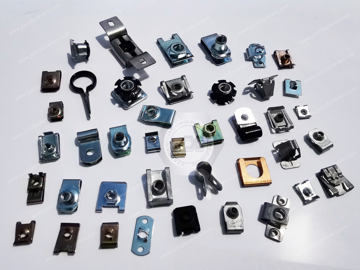
JUXIN FASTENERS supports drawing-based selection, custom development, sampling, and production sourcing for:
U-nuts
J-nuts
Clip-on nuts
Barrel clip nuts
Enclosed threaded clips
Tapping-screw clips
Low-profile spring nuts
Stainless spring clips
Custom edge-mounted fasteners
Metric and unified-inch thread configurations
Project support may include:
Drawing review
Panel-fit analysis
Throat-depth evaluation
Hole-setback review
Thread and screw compatibility
Material and hardness review
Coating evaluation
Hydrogen-risk review
Prototype coordination
Torque and retention test planning
Custom-tooling feasibility
Production and annual-volume quotation
The exact scope is defined according to the customer’s drawings, performance criteria, sample requirements, documentation requirements, and commercial volume.
Provide the fastener type, thread, mating screw, panel material, thickness range, hole diameter, hole setback, material, coating, quantity, and annual demand.
A sample can support preliminary evaluation, but drawings, panel details, performance requirements, and annual demand are still required for a controlled production quotation.
No. A 3D file supports geometry review, but a controlled drawing should define tolerances, material, thread, finish, inspection, and acceptance criteria.
The panel controls grip, throat alignment, hole position, bend clearance, installation access, and clip seating.
The screw affects thread compatibility, installation torque, friction, engagement, cross-threading risk, and strip performance.
Potentially, but the complete thickness range must be validated for installation force, retention, permanent deformation, and torque performance.
Use production-intent panel material, screw, coating, installation method, and defined dimensional and functional acceptance criteria.
Geometry, material, forming stages, thread feature, heat treatment, coating, tolerance, annual demand, automation, inspection, and tooling life all affect commercial feasibility.
Not without engineering evaluation and approval. Small differences in throat depth, panel range, hardness, coating, thread position, and spring geometry can affect assembly performance.
The most common causes are missing panel dimensions, incomplete thread specifications, unknown annual demand, undefined coating, absent mating screws, and no performance acceptance criteria.
A complete RFQ shortens technical review, improves quotation accuracy, reduces sample iterations, and prevents production misunderstandings.
Send your available technical and commercial package to:
Include:
Controlled 2D drawing
3D model where available
Mating-panel drawing
Mating screw specification
Material and hardness requirements
Surface finish
Installation and retention requirements
Torque and load criteria
Validation requirements
Quality-document requirements
Prototype quantity
Initial production quantity
Estimated annual demand
Target project schedule
If the specification is incomplete, JUXIN FASTENERS can identify the missing engineering and procurement information required for a more reliable feasibility review and quotation.
 MORE NEWS
Sep. 22, 2026
Sep. 22, 2026
Sep. 22, 2026
Contact Us
Tel.:
+86 020 8621 0320
+86 020 3121 6067
E-mail:
Technical Support:
Navigation
SEND INQUIREY