
Call Us
+86 136 6007 9809
Call Us
+86 136 6007 9809

Sep. 24, 2026
In high-density server systems, electrical cabinets, power electronics enclosures, telecommunications equipment and other serviceable industrial assemblies,
access-panel hardware must do more than simply secure a cover.
The fastener must remain attached to the panel during servicing, allow technicians to open and close the enclosure efficiently,
avoid interference with adjacent components and maintain predictable mechanical behavior throughout repeated maintenance operations.
Spring-loaded captive screws, also known as auto-retracting captive screws, spring-retracted panel screws,
spring-loaded captive panel fasteners or retractable panel screws, combine captive retention with an internal spring mechanism that biases the screw away from the mating thread after disengagement.
This creates an important functional difference from a conventional captive panel screw.
A standard captive screw remains attached to the host panel, but depending on its design, the disengaged screw may still move freely within the retainer or project behind the panel.
A spring-loaded captive screw adds controlled axial retraction.
Once the threaded portion is completely disengaged from the mating nut or threaded frame,
the spring can move the screw toward its retracted position, helping create clearance between the thread tip and the mating structure.
This function can be particularly valuable in sliding server modules, rack equipment, electrical cabinet doors,
removable covers and densely packaged assemblies where an inward-projecting screw could contact adjacent structures during panel removal.
For mechanical engineers and procurement teams, however, selecting spring-loaded captive hardware involves more than choosing a thread size.
The complete system includes the screw, spring, retainer, host-panel interface, mating thread, available retraction travel, head envelope, required service force and operating environment.
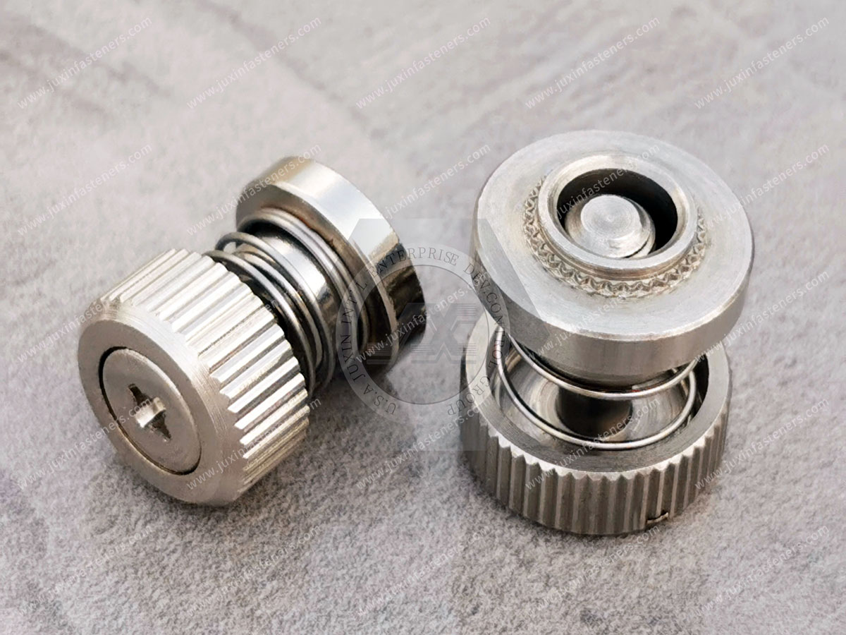
A spring-loaded captive screw is a retained panel fastener incorporating a spring element that applies axial force to the screw.
The assembly typically contains several functional components:
Threaded screw
The threaded portion engages a mating nut, threaded frame, cage nut, self-clinching nut or other compatible female thread.
Captive retainer
The retainer keeps the screw mechanically attached to the host panel after disengagement.
Compression spring
The spring biases the screw toward its disengaged or retracted position.
Head and drive system
The screw head provides the operator interface and may use a hand-operated knob, knurled head or tool-actuated drive depending on the application.
Together, these elements create a retained fastening assembly that can automatically move the threaded portion away from the mating structure after complete thread disengagement.
The operating cycle can be divided into two basic conditions.
During fastening, the operator pushes the screw toward the mating thread.
This compresses the spring while allowing the lead thread to reach the mating nut or threaded frame.
The screw is then rotated until the required fastening condition is achieved.
Depending on the application, final tightening may be performed by hand, with a screwdriver, hex tool, Torx-type drive or another specified drive system.
During servicing, the operator loosens the screw until its external thread fully disengages from the mating internal thread.
Once thread engagement no longer restrains axial movement, stored spring force acts on the screw.
The screw then moves toward its designed retracted position.
When the assembly is correctly engineered, this movement can create clearance between the screw tip and the mating chassis or frame.
That clearance is the fundamental engineering reason for specifying an auto-retracting captive screw.
Consider a removable server panel or sliding electronics module.
A conventional retained screw may be completely unthreaded but still project behind the panel.
If the technician immediately pulls the panel or module outward, the projecting screw can potentially contact:
a chassis rail;
adjacent sheet metal;
a painted surface;
a plated frame;
an internal bracket;
another removable module.
Depending on geometry and loading, that contact can contribute to scratching, mechanical interference, difficult extraction or damage to surface finishes.
In sensitive electronic equipment, avoiding unnecessary metal-to-metal scraping can also help reduce the possibility of generating unwanted metallic debris.
Spring-loaded captive screws address this design problem by providing automatic axial hold-out after disengagement.
The important engineering parameter is not simply whether the screw contains a spring.
The important question is:
Does the fully disengaged screw retract far enough to provide the required clearance from the adjacent structure?
That dimension must be evaluated against the customer's actual assembly.
Both designs retain the fastener on the host panel, but they solve different service problems.
| Engineering Factor | Standard Captive Panel Screw | Spring-Loaded Captive Screw |
|---|---|---|
| Fastener remains attached to panel | Yes | Yes |
| Loose screw prevention | Yes | Yes |
| Automatic axial retraction | Not necessarily | Yes, when designed into assembly |
| Spring-generated hold-out force | No | Yes |
| Technician must manually manage screw position | May be required | Reduced after full disengagement |
| Thread-drag control | Depends on screw position and design | Retraction can create defined clearance |
| Internal component count | Lower | Higher due to spring mechanism |
| Retainer envelope | Can be compact | Must accommodate spring and travel |
| Service access | Good | Particularly useful for frequent-access panels |
| Application complexity | Lower | Requires spring and travel evaluation |
A standard captive screw may remain the preferred choice when there is ample clearance behind the panel and automatic retraction provides little additional functional value.
A spring-loaded version becomes more attractive when the disengaged fastener must reliably move away from adjacent structures.
This distinction is important for both engineers and procurement teams.
Captive describes retention.
It means the fastener remains mechanically associated with the panel or assembly after it has been disengaged from the mating thread.
Spring-loaded or auto-retracting describes axial behavior.
It means a spring biases the disengaged screw toward a defined position.
A captive screw can therefore be non-spring-loaded.
Likewise, specifying only “captive panel screw” in an RFQ may not communicate the need for automatic thread-tip clearance.
If retraction is functionally important, it should be defined in the engineering drawing or technical specification.
Spring-loaded captive hardware operates through several mechanical interfaces that must work together.
The thread must be compatible with the mating nut, tapped component or threaded insert.
The specification should identify the required metric or inch thread, pitch or threads per inch, fit requirement where applicable and usable engagement length.
The captive retainer must remain securely installed in the access panel.
Its geometry depends on the selected mounting architecture and host-panel characteristics.
The spring must provide sufficient axial force and travel to move the screw toward its intended retracted position without creating excessive operator effort during engagement.
The disengaged screw must provide sufficient clearance for the panel's actual removal path.
Ignoring any one of these interfaces can result in a component that appears correct dimensionally but does not function correctly in the equipment.
The spring is not merely an accessory inside the fastener.
It directly influences user interaction and retraction behavior.
The fundamental spring relationship can be expressed conceptually as:
Force = Spring Rate × Compression
However, selecting the spring requires more than calculating a theoretical force.
The engineer must consider:
available compression travel;
required screw movement;
preload within the assembly;
screw mass;
friction inside the retainer;
orientation of the equipment;
required hold-out behavior;
operator depression force;
expected cycling;
operating temperature;
available spring envelope.
A spring that is too weak may not provide the desired retraction behavior under the actual assembly conditions.
A spring that is unnecessarily stiff may increase the force required to push the screw into thread engagement.
The objective is therefore not maximum spring force.
It is sufficient and repeatable retraction with acceptable engagement effort.
A common design temptation is to focus on how quickly the screw “pops out.”
In most enclosure applications, maximum retraction speed is not the objective.
The more useful requirements are:
does the screw consistently retract after complete disengagement;
does it reach the required clearance position;
does the spring maintain sufficient force throughout its intended service conditions;
can the operator comfortably depress the screw for re-engagement;
does the mechanism avoid unwanted binding.
A controlled, reliable retraction action is generally more valuable than aggressive spring motion.
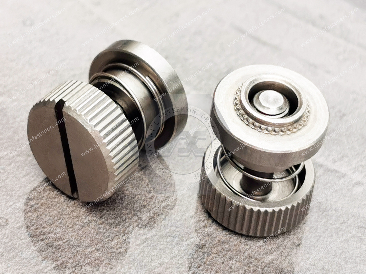
One of the most important dimensions in a spring-loaded captive screw assembly is the position of the thread tip when fully disengaged and retracted.
The required clearance depends on:
host-panel thickness;
retainer geometry;
screw length;
mating-frame position;
spring travel;
chassis extraction path;
tolerance stack-up.
For a sliding module, the engineer should consider the worst-case dimensional stack.
A nominally retracted screw may still contact the frame if manufacturing tolerances reduce the available clearance.
For this reason, retracted thread-tip position should be treated as a functional assembly dimension, not merely a catalog characteristic.
One mounting architecture uses a press-in or self-clinching retainer.
The retainer is installed into a properly prepared hole in a suitable ductile sheet.
During installation, host material flows into the fastener's retention geometry, creating mechanical attachment to the panel.
This approach can be useful in:
server chassis panels;
electronics enclosures;
electrical cabinets;
industrial control equipment;
telecommunications housings.
Successful self-clinching installation depends on the relationship between:
fastener geometry;
panel material;
panel thickness;
panel hardness;
mounting-hole dimensions;
installation force;
edge distance.
These parameters should be verified for the selected fastener and host sheet.
A self-clinching captive screw should not be assumed to work in every sheet material merely because the nominal hole diameter is correct.
Another architecture uses a retainer sleeve that passes through the panel and is mechanically flared or formed to capture the host sheet.
Flare-mounted designs can be useful where the enclosure architecture or panel material is not appropriate for a conventional self-clinching interface.
The suitability depends on the actual retainer geometry, panel material, panel thickness, hole condition and forming process.
A flare-mounted design may also be considered where the manufacturer prefers a mechanically formed retention method for a particular enclosure architecture.
The forming operation and resulting panel condition should be validated during sample qualification.
The screw head influences access, service speed, external clearance and appearance.
Knurled heads can support frequent manual access where technicians need to open panels without immediately reaching for a tool.
Some designs may combine a hand-operated external profile with an internal drive for controlled final tightening or loosening.
Potential applications include:
rack equipment;
test equipment;
instrumentation;
frequently serviced control panels.
Low-profile captive screw heads are valuable when the enclosure has restricted external space.
This can be particularly relevant in rack-mounted equipment where front-panel protrusion must be controlled.
The complete head envelope should be reviewed against:
rack doors;
neighboring modules;
handles;
cable-management systems;
adjacent controls.
Depending on the required fastener design, drive options may include slotted, Phillips, hex, Torx-type or combination configurations.
Drive selection should consider service tools, required tightening control, access angle and resistance to drive damage.
High-density computing and networking equipment creates demanding packaging constraints.
In 1U and 2U rack systems, even small hardware projections can interfere with:
adjacent equipment;
cabinet doors;
air-management components;
handles;
cable routing;
service access.
A spring-loaded captive screw for a rack application must therefore be evaluated in both states:
engaged head envelope
and
disengaged/retracted head envelope.
The designer should also consider how far the head moves outward when the spring retracts the screw.
Solving an internal thread-clearance problem should not create a new external-clearance problem.
AI computing infrastructure creates particularly strong demand for serviceable, high-density mechanical packaging.
GPU servers, accelerator chassis, power shelves and cooling systems may contain multiple removable panels and modules that require maintenance throughout equipment life.
Potential applications for spring-loaded captive screws include:
GPU server chassis faceplates;
compute-node access panels;
drive-tray covers;
power-supply module retainers;
rack-mounted power shelves;
liquid cooling distribution unit service panels;
network-switch access covers.
In these systems, the benefit is not merely preventing screw loss.
Automatic retraction can help ensure that a fully disengaged fastener moves away from the module's extraction path.
This can be valuable when equipment is densely packaged and clearance between adjacent assemblies is limited.
Power distribution units, UPS modules and power electronics enclosures frequently require controlled service access.
Potential applications include:
PDU service covers;
UPS module panels;
power-conversion enclosure doors;
shielding covers;
internal electronics access panels;
battery rack service covers.
Captive hardware helps keep the screw attached to the service panel during maintenance.
The spring-loaded function can further simplify removal where the screw must clear an internal frame after disengagement.
For energized or high-voltage equipment, the captive screw itself should not be treated as a substitute for electrical safety design, interlocks, grounding systems or enclosure safety requirements.
Those functions must be engineered separately.
Electric-vehicle power electronics and stationary energy-storage equipment use increasingly dense enclosure architectures.
Potential applications can include serviceable panels on:
inverter housings;
charging equipment;
energy-storage racks;
power conversion systems;
control cabinets;
auxiliary electrical modules.
Where the application involves environmental sealing, the complete joint architecture must be evaluated.
A spring-loaded captive screw provides mechanical fastening and retained access hardware.
It does not by itself create a specified IP rating.
Environmental sealing may require appropriately engineered gaskets, sealing interfaces, compression control and validated enclosure testing.
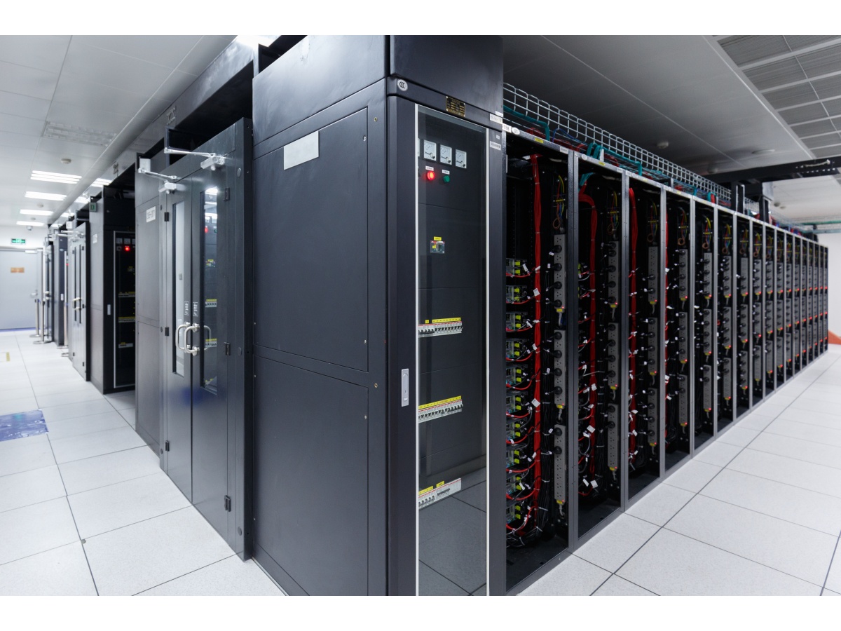
Telecommunications systems often require maintenance in restricted environments.
Applications may include:
outdoor telecom cabinets;
5G equipment enclosures;
remote radio unit access panels;
network equipment covers;
power module housings;
communications rack hardware.
Captive screws reduce the risk of technicians separating small screws from the access panel during field work.
Spring retraction can additionally help move the disengaged thread away from surrounding structures before the cover is removed.
Outdoor applications also require appropriate material and finish selection based on the specified corrosion environment.
Rail and commercial vehicle electrical systems contain numerous control cabinets and service panels exposed to vibration and repeated maintenance.
Potential applications include:
locomotive electrical cabinets;
onboard control-system enclosures;
communications equipment panels;
power distribution boxes;
diagnostic access covers.
For transportation applications, the complete fastener assembly should be evaluated against the OEM's mechanical, vibration, environmental and service requirements.
The presence of a spring does not automatically establish vibration qualification.
Diagnostic carts, laboratory instruments and medical equipment may contain removable electronic or power modules requiring service access.
Spring-loaded captive panel screws may be considered where the design requires:
retained hardware;
frequent service access;
controlled panel removal;
compact packaging;
reduction of loose components during maintenance.
Use in medical equipment does not by itself establish compliance with any medical-device requirement.
Material, cleanliness, documentation and regulatory requirements must be specified by the equipment manufacturer according to the actual application.
Industrial automation equipment often combines compact electronic packaging with frequent maintenance requirements.
Potential applications include:
robot controller cabinets;
industrial PCs;
machine-vision equipment;
PLC enclosures;
servo-drive cabinets;
automation control panels.
In these environments, spring-loaded captive screws can provide a useful combination of retained hardware and predictable disengaged positioning.
Where vibration, contamination or elevated temperature is present, those operating conditions should be included in the technical specification.
A metal captive screw may form part of a conductive assembly, but the presence of metal hardware does not automatically guarantee a defined grounding or bonding path.
Electrical performance can be affected by:
coatings;
plating;
paint;
oxide layers;
contact pressure;
mating materials;
washers;
panel finishes.
If the fastener is expected to contribute to protective bonding, chassis grounding or EMC performance, those requirements should be defined and validated as part of the complete assembly.
Mechanical retention and electrical bonding are related only when the design intentionally makes them related.
The same principle applies to sealing.
A captive screw may provide the clamp load needed to compress a panel gasket, but the fastener itself does not automatically make an enclosure waterproof.
Environmental sealing depends on:
gasket material;
gasket geometry;
compression;
screw spacing;
panel stiffness;
mating-surface flatness;
enclosure design;
environmental test requirements.
If IP or another environmental protection level is required, the complete enclosure must be designed and validated accordingly.
Spring-loaded captive screw assemblies may combine multiple materials because the screw, retainer and spring perform different functions.
Depending on the design, material options may include:
carbon steel;
stainless steel;
alloy steel;
brass;
suitable spring materials.
Material selection should consider:
mechanical strength;
corrosion environment;
temperature;
wear;
spring behavior;
host-panel compatibility;
electrical requirements;
appearance.
For stainless steel assemblies, the exact stainless grade should be specified when material composition matters.
Terms such as “stainless” alone may not provide enough information for engineering qualification.
Carbon-steel components may use different surface treatments depending on corrosion, appearance and assembly requirements.
Possible finishes can include zinc-based coatings, zinc-nickel systems or other specified treatments.
Stainless components may be supplied with appropriate surface treatment according to the customer's requirements.
The correct finish should be selected from the actual operating environment and specification.
A coating name alone should not be used to infer a particular corrosion life without defined coating specification, thickness, substrate, pretreatment and test requirements.
If salt-spray or other corrosion testing is required, the acceptance criteria should be stated in the RFQ or drawing.
Spring-loaded captive hardware may experience repeated compression during the service life of the equipment.
Applications with frequent maintenance should therefore consider the expected cycling profile.
Important factors include:
spring material;
spring geometry;
compression range;
operating stress;
temperature;
corrosion environment;
assembly friction;
required residual retraction force.
Rather than assuming unlimited reusability, engineers should define the service expectations appropriate to the equipment.
Where cycle life is critical, sample testing can be performed against the customer's acceptance criteria.
Strategic sourcing teams often need to qualify an alternative source for an existing spring-loaded captive screw.
A successful cross-reference requires more than matching thread size.
The candidate fastener should be reviewed against the complete functional geometry.
Confirm:
nominal thread;
pitch or threads per inch;
thread fit where specified;
threaded length;
mating-thread compatibility.
Confirm:
mounting-hole diameter;
panel thickness;
panel material;
panel hardness where relevant;
mounting method;
retainer geometry.
Confirm:
available spring travel;
screw movement;
fully retracted thread-tip position;
required hold-out clearance;
external head position after retraction.
Evaluate:
depression force;
retraction behavior;
smoothness of travel;
resistance to binding;
required service cycling.
Verify:
head diameter;
head height;
drive type;
tool accessibility;
available external clearance.
Confirm the required:
screw material;
retainer material;
spring material;
plating or passivation;
corrosion requirement;
appearance requirement.
These characteristics should be compared against the customer's drawing and actual assembly rather than inferred from catalog appearance.
Spring-loaded captive assemblies contain interacting moving parts.
Two products with similar nominal dimensions may behave differently because of variations in:
spring force;
internal friction;
retainer geometry;
screw travel;
surface finish;
tolerance stack-up.
For this reason, physical sample validation can be especially valuable during second-source qualification.
A practical sample review can evaluate:
Installation
Does the retainer install correctly in the actual panel?
Retention
Does the retainer remain securely attached after installation?
Thread engagement
Can the operator depress and engage the screw smoothly?
Retraction
Does the screw consistently move to the required disengaged position?
Clearance
Does the thread tip clear the mating structure throughout the panel-removal path?
Serviceability
Can technicians operate the fastener comfortably using the intended tools and access conditions?
This creates a much stronger qualification process than approving an alternative from dimensions alone.
Standard products can solve many enclosure applications, but custom hardware may be required when the assembly has unique constraints.
Customization may involve:
thread size;
thread length;
screw overall length;
retainer diameter;
panel grip range;
spring travel;
retracted clearance;
spring force;
head geometry;
drive style;
material;
surface finish;
mounting architecture.
For custom programs, the customer's 2D drawing should define critical dimensions and functional requirements.
A physical sample can also be useful when developing a functional alternative to existing hardware.
A complete RFQ helps engineering teams evaluate feasibility and allows procurement teams to obtain more accurate commercial information.
For spring-loaded captive screws, provide the following information where available.
Send:
2D drawing;
3D model where useful;
existing part specification;
physical sample information if cross-referencing.
Specify:
panel material;
panel thickness;
panel hardness where relevant;
mounting-hole diameter;
hole tolerance;
available installation access.
Specify:
metric or inch thread;
pitch or threads per inch;
required threaded length;
mating-thread type.
Identify whether the application requires:
self-clinching / press-in mounting;
flare mounting;
another retained mounting architecture.
Where critical, define:
required screw travel;
required retracted thread-tip position;
minimum chassis clearance;
desired depression force or spring behavior;
expected service cycles.
Specify:
hand-operated or tool-operated;
head diameter;
maximum head height;
drive style;
available external clearance.
Specify:
screw material;
retainer material where required;
corrosion environment;
coating or passivation requirement;
any electrical or appearance requirements.
Provide:
prototype quantity;
sample quantity;
pilot quantity;
estimated annual usage;
target production date;
packaging requirements.
These details allow the supplier to evaluate the complete fastening system rather than quoting an incomplete description such as “M4 spring captive screw.”
Spring-loaded captive screws are more complex than ordinary screws because they combine several functional components into one retained assembly.
Their commercial value should therefore be evaluated against the assembly and service process.
A sourcing analysis may consider:
fastener unit price;
retainer installation process;
assembly time;
number of loose components eliminated;
service time;
lost-hardware risk;
potential panel interference;
rework;
tooling;
expected annual usage.
For high-volume server, telecommunications and electrical equipment programs, these process costs may materially influence the sourcing decision.
A useful approach for engineers is to evaluate the fastener in reverse.
Instead of beginning with:
“What captive screw fits this panel?”
begin with:
“Where must the thread tip be when the panel is being removed?”
That establishes the required retracted position.
From there, the engineer can work backward through:
required screw travel;
spring compression range;
retainer length;
panel thickness;
thread engagement;
head movement.
This approach directly addresses the interference problem the spring-loaded fastener is intended to solve.
Spring-loaded captive screws solve an internal clearance problem by moving the screw outward.
That means the design must evaluate two envelopes simultaneously.
Inside the enclosure
The retracted thread must clear the chassis, rail, frame or adjacent module.
Outside the enclosure
The retracted head must not create unacceptable interference with cabinet doors, handles, adjacent equipment or service operations.
This two-sided clearance analysis is particularly important in high-density rack equipment.
The spring force influences not only mechanical retraction but also technician interaction.
If depression force is unnecessarily high, repeated servicing can become uncomfortable or make thread engagement difficult.
If it is too low for the particular mechanism and orientation, retraction may be less positive than required.
The correct spring specification therefore balances:
reliable retraction + comfortable engagement + required travel + expected service life.
This is why spring-loaded captive screws should be treated as engineered assemblies rather than ordinary commodity screws.
Spring-loaded captive screws belong to a broader family of engineered panel-access hardware.
Depending on the application, design and sourcing teams may also evaluate:
Captive Panel Screws
For retained panel fastening where automatic retraction is not required.
Low-Profile Captive Screws
For access panels with restricted external head clearance.
Floating Self-Clinching Nuts
For mating threads requiring controlled alignment compensation.
Blind Self-Clinching Nuts
For applications where the thread or backside architecture requires a blind configuration.
Snap-In Standoffs
For toolless PCB mounting and board-support applications.
Self-Clinching Fasteners
For permanent threaded attachment points in suitable sheet metal.
Custom Metal Panel Fasteners
For assemblies requiring special retention, clearance, material or installation geometry.
Selecting among these technologies should begin with the assembly problem rather than a predetermined fastener category.
For OEM and industrial sourcing programs, the most efficient commercial path is:
Identify the panel-access or thread-drag problem
→ Define the required retracted screw position
→ Confirm panel and mating-thread geometry
→ Select mounting architecture
→ Review spring travel and operating force
→ Evaluate material and finish
→ Produce or review engineering drawings
→ Request samples
→ Validate installation, engagement and retraction
→ Complete supplier qualification
→ Release production sourcing
This process helps mechanical engineers, procurement managers and supply-chain development teams avoid selecting hardware based only on nominal thread size or visual similarity.
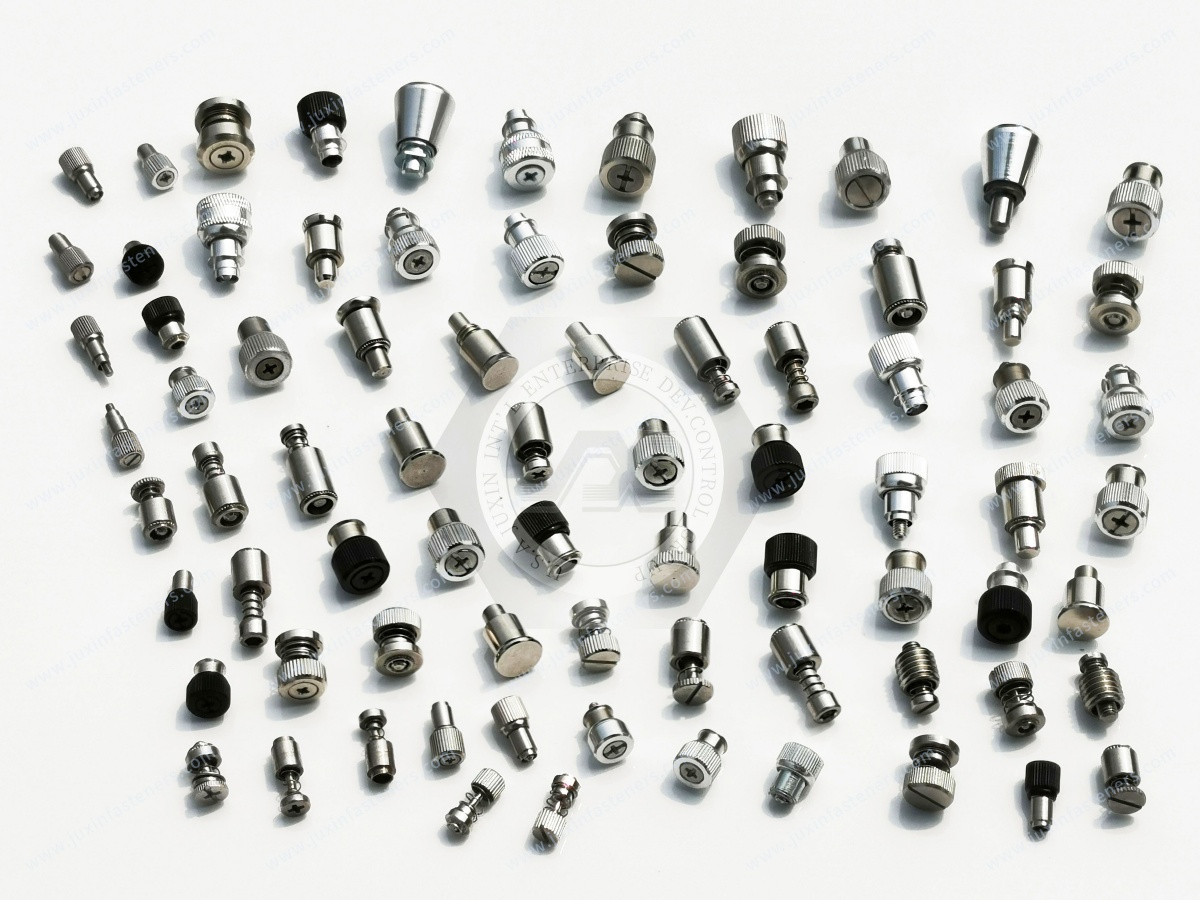
JUXIN FASTENERS manufactures and supplies engineered fastening solutions for industrial OEM applications, including spring-loaded captive screws,
captive panel screws, auto-retracting panel fasteners, self-clinching hardware and custom metal panel fasteners.
We support applications across server infrastructure, electrical equipment, power electronics, telecommunications, industrial automation, transportation equipment and other engineered enclosure systems.
For drawing-based projects, our team can review customer specifications covering:
thread geometry;
host-panel thickness;
mounting-hole requirements;
retainer design;
retraction travel;
thread-tip clearance;
head envelope;
mounting architecture;
material;
finish;
sample requirements;
annual production demand.
For second-source programs, customers can provide an existing 2D drawing, technical specification or physical sample for dimensional and functional review.
Where spring behavior or retracted clearance is critical, sample validation in the actual customer assembly is recommended before production approval.
If your project requires spring-loaded captive screws, auto-retracting captive panel screws, custom enclosure fasteners or functional-equivalent captive hardware,
send us your available drawing and application requirements.
For the fastest engineering review, include the host-panel material and thickness, mounting-hole dimensions, thread specification, required retracted clearance,
head/drive preference, material or finish requirements and estimated annual usage.
This allows the project to move from technical review → sample validation → supplier qualification → production quotation with fewer clarification cycles.
Email: info@juxinfasteners.com
Website: www.juxinfasteners.com
 MORE NEWS
Sep. 24, 2026
Sep. 24, 2026
Contact Us
Tel.:
+86 020 8621 0320
+86 020 3121 6067
E-mail:
Technical Support:
Navigation
SEND INQUIREY