
Call Us
+86 136 6007 9809
Call Us
+86 136 6007 9809

Oct. 28, 2023
Spring steel is widely used in fasteners and stamped components that must elastically deflect, recover their shape, retain a component, grip a panel, or maintain contact force.
Typical examples include:
Spring nuts
Clip nuts
U-nuts
Speed nuts
Retaining clips
Spring clips
Panel fasteners
Electrical contact clips
Custom stamped spring components
But selecting spring steel is not simply a matter of choosing a material described as “high elasticity.”
The performance of a spring-steel fastener depends on the complete relationship between:
material + heat-treatment condition + thickness + geometry + forming process + deflection + environment + assembly interface
For design engineers, this means that material selection cannot be separated from component geometry.
For procurement and supplier-development teams,
it means that two clips that look nearly identical may not be functionally interchangeable if their material condition, hardness, geometry, or forming process differs.
This guide explains how to evaluate spring steel for industrial fasteners and drawing-controlled spring components.
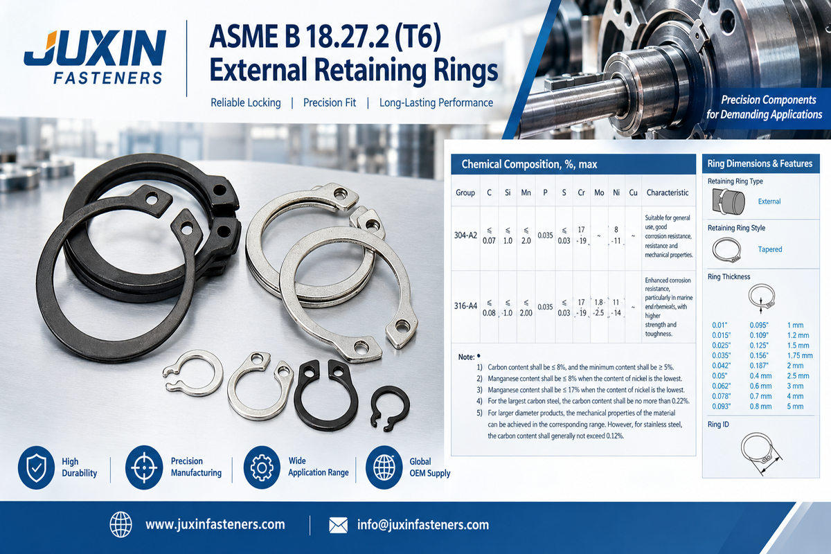
Spring steel refers to steels selected and processed for applications requiring controlled elastic deformation and recovery.
In a spring fastener, the material is typically deflected during:
Installation
Component insertion
Panel engagement
Screw installation
Assembly
Service
The component should then provide the mechanical response required by the design.
The important engineering question is not simply:
“Is this spring steel?”
It is:
“Can this material, in this condition and geometry, provide the required elastic behavior for this specific fastener?”
A common misconception is that spring steel works mainly because it has an unusually high elastic modulus compared with other steels.
That is an oversimplification.
For many steels, elastic modulus is broadly similar.
What often matters more for spring-component design is the material's ability to operate within the intended elastic range without unacceptable permanent deformation or fracture.
Important variables can include:
Yield behavior
Tensile properties
Hardness
Heat-treatment condition
Fatigue behavior
Ductility
Formability
Surface condition
These characteristics must be considered together with the geometry of the fastener.
Understanding this distinction is essential.
The component deflects under load and substantially recovers when the load is removed.
The material exceeds its elastic capability and retains permanent deformation after unloading.
For a clip nut, U-nut, retaining clip, or spring contact, excessive permanent deformation can reduce:
Retention
Alignment
Grip
Contact force
Reusability
This is why simply making a clip “stiffer” does not necessarily improve its performance.
A spring fastener cannot be evaluated from material properties alone.
Its behavior also depends on:
Material thickness
Free-state geometry
Bend geometry
Clip length
Width
Slot geometry
Local features
Installation deflection
Contact location
Panel thickness
Mating component geometry
Changing any of these can change how stress is distributed through the part.
Therefore:
same material ≠ same spring performance
and:
same geometry ≠ same performance if material condition changes
A spring component must normally operate within a suitable mechanical range for its intended design.
If installation forces the material beyond the intended range, the part can take a permanent set.
For example, a U-nut designed for one panel thickness may be excessively opened when forced onto a much thicker panel.
After removal, it may no longer return sufficiently toward its original shape.
This can reduce retention during subsequent installation.
The failure may look like a material problem even though the root cause is actually an interface mismatch.
Spring steel performance can depend strongly on material condition and thermal processing.
Depending on the material and manufacturing route, heat treatment can influence:
Strength
Hardness
Elastic range
Toughness
Formability
Fatigue behavior
This means a drawing should not assume that identifying a generic steel family alone completely defines the finished spring component.
Where material condition or hardness is functionally important, it should be specified according to the customer's engineering requirements.
JUXIN FASTENERS does not recommend assigning arbitrary hardness values without a defined product requirement.
Increasing hardness can change several properties simultaneously.
A harder component may offer certain mechanical advantages, but excessive hardness for the geometry or forming process can also increase sensitivity to:
Cracking
Brittle behavior
Forming damage
Stress concentration
The correct material condition depends on the component design and manufacturing process.
For spring fasteners, the goal is not maximum hardness.
The goal is the required mechanical response.
Many spring fasteners begin as strip or sheet material and are produced through operations such as:
Blanking
Piercing
Stamping
Bending
Forming
Thread-forming features
Heat treatment where required
Surface finishing
A material that performs well in the finished component must also be compatible with the intended manufacturing route.
This is particularly important for complex stamped parts containing:
Tight bends
Tabs
Lances
Slots
Embossments
Thread-engagement features
Multiple forming operations
Bending creates local strain.
The severity depends on factors including:
Material
Thickness
Material condition
Bend radius
Bend angle
Forming direction
Manufacturing process
An unnecessarily tight bend can create a high local strain region.
For spring components that repeatedly deflect near a formed bend, this area may become particularly important.
The bend should therefore be designed as part of the spring system rather than merely as a packaging feature.
Sheet and strip materials can exhibit directional characteristics resulting from their processing history.
For some spring-component designs, the relationship between material direction and critical bends may therefore deserve consideration.
This becomes more relevant where:
Bend radii are small
Material strength is high
Geometry is sensitive
Cracking risk must be controlled
Fatigue performance is important
The required manufacturing controls depend on the specific component and material.
Failures frequently begin at geometric discontinuities rather than in the middle of a smooth section.
Potential stress-concentration locations include:
Sharp internal corners
Slot ends
Pierced holes
Notches
Narrow transitions
Tight bends
Stamped lances
Thread-engagement features
A component may therefore fail even though the nominal material strength appears adequate.
Good spring-fastener design considers where the stress is concentrated, not just the overall load.
Stamping and blanking create cut edges.
Depending on component design, edge condition can matter where the edge is located near:
A highly stressed bend
A repeatedly flexed section
A retention feature
A contact region
Tooling condition and manufacturing quality can therefore influence the behavior of small stamped spring components.
This is one reason physical samples can be valuable during second-source qualification.
A spring fastener may experience deflection:
Once during assembly
Several times during maintenance
Repeatedly during service
These are different design conditions.
A clip installed once and left stationary should not automatically be evaluated in the same way as a spring component that repeatedly cycles.
Fatigue behavior depends on variables such as:
Stress range
Geometry
Surface condition
Material
Heat-treatment condition
Number of cycles
Environment
Universal fatigue-life claims should therefore be avoided without application-specific validation.
Some spring clips and clip nuts can be removed and reinstalled where the product design permits.
But “reusable” should not be interpreted as unlimited assembly cycles.
Repeated installation can change:
Spring geometry
Contact surfaces
Coating condition
Retention behavior
Thread engagement
Where repeated service is a requirement, the intended assembly cycle and validation method should be defined.
Another common misconception is that spring steel inherently provides strong corrosion resistance.
Carbon and alloy spring steels can require suitable surface protection depending on the service environment.
Corrosion behavior depends on:
Base material
Surface treatment
Environment
Moisture
Chlorides
Chemicals
Temperature
Contact with other materials
Do not assume that spring properties imply corrosion resistance.
These are separate engineering considerations.
Depending on the part and customer specification, spring steel components may use a suitable surface finish for purposes such as:
Corrosion protection
Appearance
Assembly requirements
Contact behavior
The appropriate finish depends on the application.
A finish should not be selected only because it is commonly used on another fastener.
This is particularly important for precision clip components.
Coating buildup can influence:
Slot dimensions
Panel engagement
Thread engagement
Clip opening
Contact surfaces
Assembly force
For small spring nuts and clips, dimensional control should therefore consider the finished component rather than only the uncoated stamped part.
For certain high-strength steel components, manufacturing and finishing processes can introduce hydrogen-embrittlement considerations.
The actual risk depends on:
Material strength
Hardness
Manufacturing process
Surface treatment
Applied stress
Component geometry
This issue should be evaluated where relevant to the selected material and finishing route.
It should not be assumed that every spring steel component has the same susceptibility.
This is an important material-selection decision.
Can provide suitable spring properties and manufacturing economics for many applications, with surface protection selected where required.
May be considered where corrosion resistance is an important design requirement.
However, changing from carbon spring steel to stainless steel is not simply a corrosion upgrade.
Material properties, forming behavior, spring response, geometry, and cost can differ.
A substitution should therefore be reviewed as an engineering change.
Suppose an existing clip is designed around a particular spring steel.
Changing only the material while keeping identical:
Thickness
Bend geometry
Free-state opening
Deflection
may change the mechanical behavior.
Material substitution should consider the complete component design.
This is especially important for second-source development.
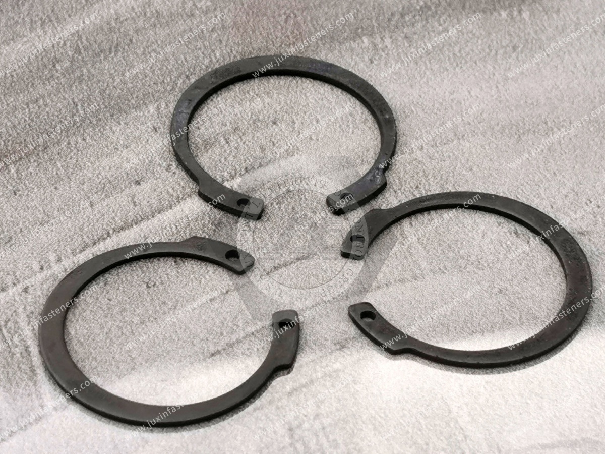
Clip nuts and U-nuts are excellent examples of spring steel functioning as part of the fastening system.
The spring body can:
Grip a panel edge
Position a threaded feature
Maintain assembly location before screw installation
Accommodate a designed panel thickness range
Their performance depends on more than thread size.
Important parameters include:
Panel thickness
Grip range
Clip reach
Hole location
Thread position
Free-state opening
Material thickness
Spring geometry
Possible causes include:
Panel outside the intended grip range
Incorrect free-state geometry
Permanent deformation
Insufficient retention feature
Material condition mismatch
Coating buildup
Incorrect clip size
The solution is not automatically to specify harder spring steel.
First identify the interface problem.
High installation force can result from:
Panel too thick
Clip opening too small
Excessive material thickness
Spring geometry
Material condition
Coating buildup
Burr or edge condition
Increasing installation force may also deform or damage the panel.
The correct design balances retention with assembly requirements.
Cross-threading may be caused by more than the thread itself.
Possible contributors include:
Thread misalignment
Panel-hole position
Clip movement
Tolerance stack-up
Incorrect mating screw
Distortion of the clip
Improper assembly angle
This demonstrates why a spring nut should be evaluated as an assembly interface rather than simply as a threaded nut.
Consider a clip nut installed over a sheet-metal panel.
The screw must align through:
The mating component
The panel hole
The clip nut thread
Each feature has positional and dimensional tolerances.
If the combined tolerance stack exceeds the available alignment capability, assembly problems can occur even when each individual part passes inspection.
Engineers should therefore consider assembly-level tolerance, not only individual component dimensions.
Retaining clips can use elastic deformation to engage:
Shafts
Grooves
Panels
Edges
Housings
Other components
Important design considerations include:
Installation direction
Removal requirements
Groove or panel geometry
Retention requirement
Material thickness
Stress concentration
Environment
Retaining clips should not be confused with retaining rings where the geometries and applicable product standards differ.
Spring steel components can be used in suitable electrical equipment for mechanical functions such as:
Retention
Mounting
Panel fastening
Component positioning
Enclosure assembly
Where the component also performs an electrical function, additional requirements may apply.
Mechanical spring performance alone does not establish electrical suitability.
Automotive assemblies can use spring steel fasteners in areas such as:
Body panels
Interior assemblies
Exterior trim
Brackets
Electrical enclosures
Equipment mounting
Depending on location, the component may experience:
Vibration
Temperature variation
Moisture
Road contamination
Repeated service
Material, geometry, and surface finish should therefore be selected for the actual installation.
Clip nuts, spring clips, and stamped retaining components can be useful in:
Cabinets
Enclosures
Equipment housings
Mounting structures
Access panels
For these applications, engineers may prioritize:
Fast assembly
Captive positioning
Service access
Sheet-metal compatibility
Panel thickness and hole geometry should be defined early in the design.
Data center and AI/HPC infrastructure contains substantial amounts of:
Sheet-metal enclosures
Equipment racks
Cooling equipment
Power-distribution equipment
Electronic assemblies
Spring clips, clip nuts, U-nuts, and related stamped fasteners may be used where appropriate for panel and equipment assembly.
Selection should consider:
Sheet thickness
Service access
Vibration
Corrosion environment
Assembly process
Required retention
HVAC equipment commonly contains:
Sheet-metal housings
Access panels
Fan assemblies
Cooling equipment
Brackets
Spring fasteners can support efficient assembly where their geometry matches the panel system.
The correct clip should be selected from the actual panel and mating screw requirements.

Spring clips and stamped fasteners can be used in:
Guards
Enclosures
Control cabinets
Equipment panels
Brackets
Service covers
Maintenance requirements are particularly important.
If a panel must be removed frequently, the fastener should be evaluated for the intended service cycle.
For a drawing-controlled spring steel fastener or stamped spring component, consider defining:
Material
Material condition where required
Thickness
Critical dimensions
Free-state geometry
Bend geometry
Holes and slots
Thread requirements
Surface finish
Critical interface dimensions
Functional requirements
Do not add arbitrary hardness, fatigue, or load requirements simply to make the drawing appear more technical.
Every requirement should correspond to a real functional need.
For a clip nut, critical dimensions may include:
Panel grip
Clip reach
Thread location
Opening
Hole alignment
For a retaining clip, they may include:
Engagement geometry
Free-state opening
Retention feature
Contact location
A drawing should distinguish dimensions that control assembly function from dimensions that have little functional influence.
For an existing production part, a physical approved sample can provide information that may not be fully captured in an old drawing.
Useful observations can include:
Free-state shape
Material thickness
Bend geometry
Edge condition
Thread form
Surface finish
Contact marks
Assembly relationship
However, sample matching should not rely only on visual appearance.
Material and functional requirements still need to be established.
When qualifying an alternative supplier for a spring steel fastener, compare:
Material specification
Material condition where required
Thickness
Free-state dimensions
Bend geometry
Critical features
Thread or retention geometry
Finish
Coating condition
Edge condition
Panel thickness
Hole geometry
Mating screw or component
Installation method
Installation behavior
Retention behavior
Alignment
Removal requirements
Final acceptance should follow the customer's qualification requirements.
Two spring clips can look almost identical while behaving differently.
Possible hidden differences include:
Material grade
Heat-treatment condition
Hardness
Thickness
Bend radius
Free-state opening
Surface finish
For second-source development:
appearance is evidence, not specification.
Provide:
Drawing or sample
Thread size
Panel thickness
Panel material
Panel-hole dimensions
Clip reach
Material requirement
Finish
Mating screw information
Quantity
Annual demand
Provide:
2D drawing
3D model where available
Material
Thickness
Mating component
Installation method
Required deflection or functional movement where defined
Environment
Surface finish
Quantity
Annual demand
If the material is not yet finalized, provide the application requirements rather than guessing a grade.
For an existing production component, provide where available:
drawing + unused approved sample + material specification + mating panel/component + installation method + finish + annual demand
Also identify the commercial objective:
Alternative supplier qualification
Supply continuity
Capacity expansion
Lead-time reduction
Cost review
Regional sourcing
This allows technical and commercial requirements to be evaluated together.
Related engineering and sourcing resources include:
Spring Nuts
Clip Nuts and U-Nuts
Leaf Spring Nuts
Retaining Clips
Stainless Steel Fasteners
Custom Stamped Components
Automotive Fasteners
Electrical Equipment Fasteners
Custom Fasteners
Second-Source Fasteners
These resources can support engineers and sourcing teams working with complete sheet-metal and mechanical assemblies.
JUXIN FASTENERS supports standard and custom industrial fasteners, including spring-based fastening components and drawing-controlled parts for OEM applications.
Project review can begin from:
Customer drawing
Existing specification
Approved sample
Material requirement
Panel or mating component information
Surface finish
Application environment
Order quantity
Annual demand
For existing components, drawings and approved samples can be reviewed together to understand the dimensional and functional interface.
For new designs, providing the mating panel or assembly information helps define the actual engineering requirements.
The correct engineering path is:
assembly function → required deflection → interface geometry → material → material condition → thickness → forming geometry → finish → validation
For procurement and supplier-development teams:
drawing/sample → material → critical geometry → mating component → finish → functional requirements → annual demand → qualification
The most important lesson is simple:
Spring steel does not create a successful spring fastener by itself.
Reliable performance comes from the relationship between the material, its condition, the component geometry, the manufacturing process, and the actual assembly interface.
If you require spring nuts, clip nuts, U-nuts, spring clips, retaining clips, custom stamped spring steel components, or second-source development for an existing OEM part,
send JUXIN FASTENERS your available technical information.
For an existing component, provide the drawing and unused approved sample where available.
For a new component, provide the application, mating geometry, required function, material requirements if defined, environment, quantity, and annual demand.
For second-source development, provide the existing drawing, approved sample, mating components, material and finish requirements, and annual volume for technical review.
Email: info@juxinfasteners.com
Website: www.juxinfasteners.com
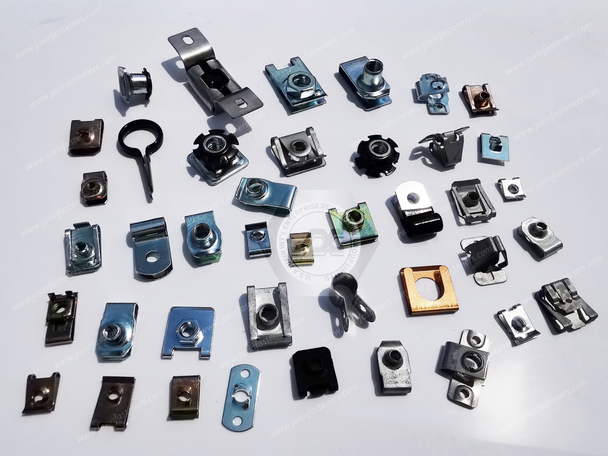
 MORE NEWS

Sep. 27, 2026

Sep. 27, 2026

Sep. 27, 2026
Contact Us
Tel.:
+86 020 8621 0320
+86 020 3121 6067
E-mail:
Technical Support:
Navigation
SEND INQUIREY