Call Us
+86 136 6007 9809
Call Us
+86 136 6007 9809

Nov. 20, 2023
Self-tapping threaded inserts are used to create durable internal threads in materials where directly tapped threads may not provide sufficient strength, wear life, or serviceability.
Typical parent materials include aluminum alloys, magnesium alloys, engineering plastics, cast materials, copper alloys, and selected composite structures.
Unlike many conventional threaded insert systems, a self-tapping insert is installed into a correctly sized pilot hole without requiring the parent material to be pre-tapped.
Its external cutting or forming geometry creates its own engagement with the surrounding material while the internal thread provides a reusable fastening interface for a mating screw or bolt.
For design engineers, however, selecting a self-tapping insert involves more than matching the internal thread size.
Pilot-hole diameter, parent-material strength, boss geometry, insert length, installation torque, wall thickness, edge distance, corrosion compatibility,
and required pull-out or torque-out performance can all influence the reliability of the final joint.
JUXIN FASTENERS supplies self-tapping threaded inserts and drawing-based thread reinforcement solutions for industrial OEM, machinery, automotive,
electrical equipment, transportation, electronics, and other engineered assemblies.
This engineering guide explains how self-tapping inserts work, where they should be considered, how to select them, what causes installation failures,
and what engineers and procurement teams should specify when requesting a quotation.
A self-tapping threaded insert should be considered when a component requires a stronger or more durable female thread than the parent material can reliably provide.
Typical situations include:
threaded joints in aluminum or other relatively soft alloys;
reusable threads in engineering plastics;
repair of stripped or damaged internal threads;
repeated assembly and disassembly;
cast components where direct threads have insufficient service life;
production designs where eliminating a separate pre-tapping operation is advantageous;
applications requiring a replaceable threaded interface;
components where load must be distributed over a larger external engagement area.
The important engineering distinction is that the insert does not automatically make every threaded joint stronger.
Performance depends on the interaction between the insert geometry, parent material, pilot hole, installation process, engagement length, mating fastener, and surrounding component geometry.
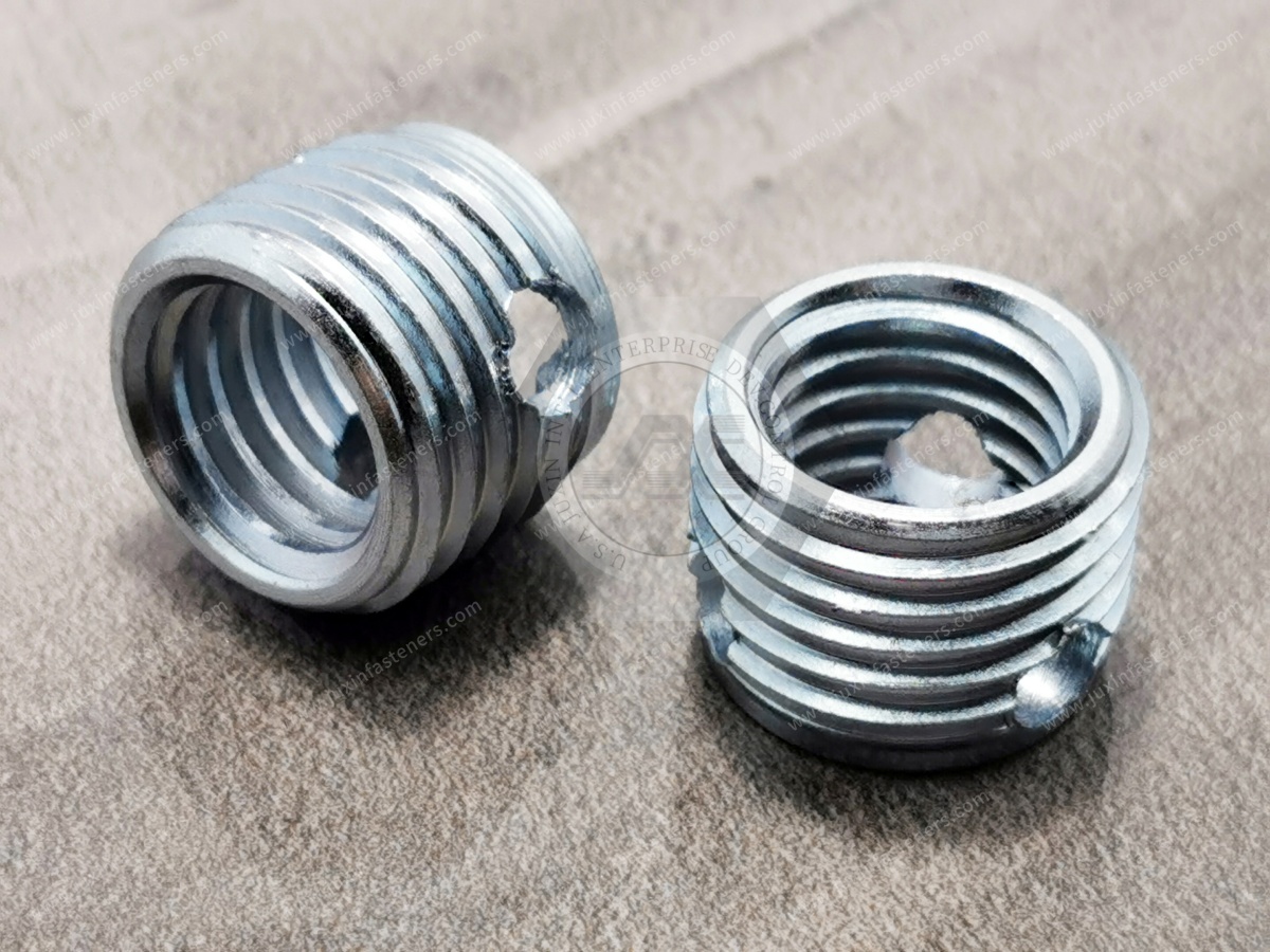
A self-tapping threaded insert is a metal threaded sleeve with an internal machine thread and an external self-tapping geometry.
During installation, the external geometry cuts or forms its engagement into a prepared pilot hole. Once installed, the internal thread accepts a standard mating screw of the specified thread size.
The component may also be described in industrial searches as a:
self tapping insert;
self tapping threaded insert;
tapping insert;
threaded insert for aluminum;
threaded insert for plastic;
threaded insert for soft metal;
metal threaded insert for plastic;
thread reinforcement insert;
thread repair insert;
self tapping screw sleeve.
Terminology varies by industry and drawing system, so procurement teams should identify the actual geometry, dimensions, material,
thread specification, and application rather than relying on a product name alone.
The installation sequence normally begins with a drilled or molded pilot hole rather than a pre-tapped hole.
The basic process is:
Prepare the pilot hole to the specified diameter and depth.
Align the insert with the hole axis.
Drive the insert using the appropriate installation tool.
Allow the external cutting or forming features to engage the parent material.
Install the insert to the specified depth.
Remove the installation tool and inspect the internal thread and installed position.
Assemble the mating screw according to the joint requirements.
The external diameter of the insert is larger than the internal machine thread it carries.
This allows the insert to engage a larger volume of parent material than a directly tapped screw of the same nominal internal thread size.
This larger load-transfer interface is one reason self-tapping inserts can be useful in lower-strength materials.
However, the surrounding material still determines the ultimate capability of the joint. If the boss is too thin, the pilot hole is incorrect,
or installation generates excessive radial stress, the component can crack or deform before the theoretical insert strength is reached.
The pilot hole is not simply a clearance hole. It directly affects installation torque, external thread engagement, pull-out resistance, and the stress generated in the parent material.
A hole below the recommended range may cause:
excessive installation torque;
difficult insert alignment;
insert damage;
tool overload;
excessive radial stress;
boss expansion;
cracking in brittle plastics or cast materials;
deformation of thin-wall components.
An oversized hole may reduce external thread engagement and can contribute to:
lower pull-out resistance;
reduced torque-out resistance;
insert rotation;
poor positional stability;
inconsistent assembly performance.
Therefore, the correct pilot-hole diameter should be selected according to the insert geometry and the actual parent material rather than copied blindly from a generic chart.
For production applications, especially in plastics, castings, and lightweight alloys, validation using the actual component material is preferable to relying only on nominal material descriptions.
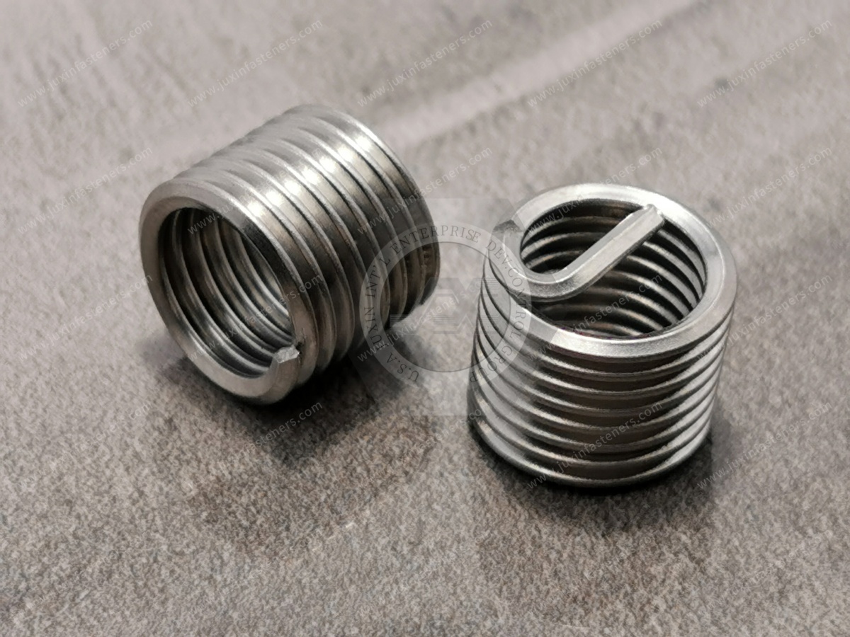
A pilot hole suitable for one material may not be optimal for another.
Aluminum is one of the most common parent materials for self-tapping threaded inserts.
Applications may include:
cast aluminum housings;
electronic enclosures;
power electronics housings;
machinery components;
heat-management structures;
transmission and drive-system components;
automation equipment.
The specific aluminum alloy and condition matter. A soft cast aluminum component and a higher-strength wrought aluminum component can require different installation conditions.
Engineers should consider:
alloy and temper;
casting porosity;
available wall thickness;
hole quality;
required thread load;
installation torque;
corrosion compatibility.
Metal self-tapping inserts can provide a durable reusable thread in selected thermoplastics and other polymer components.
Relevant variables include:
polymer type;
filler or reinforcement content;
molded boss diameter;
wall thickness;
temperature;
creep behavior;
assembly torque;
repeated service cycles.
A glass-filled engineering polymer, for example, does not necessarily behave like an unfilled version of the same resin.
Brittle or highly filled materials require particular attention to pilot-hole size and boss geometry because installation stresses can initiate cracking.
Self-tapping inserts may also be considered for appropriate cast components, but the material's hardness, brittleness, microstructure, and available surrounding section must be evaluated.
The insert design and pilot hole should be selected for the actual casting rather than assuming that all cast materials behave identically.
Thread reinforcement can be valuable in lightweight structures, but material compatibility and corrosion behavior become particularly important.
Where dissimilar metals are combined, the complete assembly environment should be evaluated for galvanic corrosion risk.
Direct tapping remains appropriate for many components. An insert is most valuable when the design requires capabilities that the parent-material thread may not reliably provide.
| Engineering Factor | Direct Thread in Parent Material | Self-Tapping Threaded Insert |
|---|---|---|
| Machining steps | Drilling plus tapping normally required | Pilot hole; insert creates external engagement during installation |
| Thread material | Same as parent component | Metal insert provides internal mating thread |
| Repeated assembly | Depends strongly on parent material | Can improve wear durability in suitable applications |
| Repairability | Damaged thread may require rework | Insert can provide a replacement threaded interface |
| Load distribution | Limited by direct thread geometry | Larger external insert engagement can distribute load over more parent material |
| Component cost | Fewer added components | Additional insert and installation operation |
| Design validation | Thread strength must be validated | Insert, hole, parent material, installation and joint must all be validated |
A self-tapping insert should therefore be treated as an engineered interface, not automatically as a universal replacement for direct tapping.
Both systems can reinforce or repair internal threads, but their installation principles differ.
A helical wire thread insert normally requires a specially prepared tapped hole compatible with the insert system. A self-tapping solid insert creates its own external engagement in a correctly prepared pilot hole.
A self-tapping insert may be attractive when eliminating the parent-material tapping operation is important.
A helical insert may be appropriate when its specific thread-reinforcement characteristics, envelope, weight, or established assembly process match the design.
The correct choice depends on:
parent material;
available wall thickness;
required thread size;
available installation equipment;
repair versus original production;
pull-out requirements;
torque requirements;
service conditions;
component geometry.
Related Engineering Guide: Wire Thread Inserts and Thread Repair Solutions
Slotted self-tapping inserts use a cutting slot at one end of the insert to help create the external thread path during installation.
They are commonly considered for suitable:
aluminum alloys;
non-ferrous metals;
plastics;
cast materials;
industrial housings.
The slot provides cutting geometry, but insert suitability still depends on parent-material hardness and component design.
For engineering drawings and RFQs, specifying only “slotted insert” is usually insufficient.
Dimensions, internal thread, external geometry, insert length, material, finish, and installation requirements should also be defined.
Another common solid-insert configuration uses cutting holes or cutting features around the insert body rather than a single open slot.
These products are often searched using series terminology such as 307/308 self-tapping inserts.
Because series designations can vary by supplier or product system, engineers should not rely on the number alone when qualifying an alternative source.
For sourcing and cross-referencing, compare:
internal thread;
external thread geometry;
overall length;
outside diameter;
cutting-feature geometry;
installation direction;
material;
surface finish;
recommended pilot hole;
installation depth;
mechanical performance requirements.
This dimensional comparison is especially important when a procurement team is qualifying a second source against an existing insert.
Self-tapping inserts serve two related but different engineering purposes.
For new designs, the insert can be specified from the beginning to provide a durable internal thread in a lightweight or relatively low-strength parent material.
The surrounding boss and hole can then be designed specifically for the insert.
For maintenance or rework, a self-tapping insert may replace a stripped or damaged direct thread.
However, thread repair requires more than simply installing an insert into the damaged hole.
The engineer should verify:
remaining hole diameter after damage;
available parent material;
insert outside diameter;
minimum wall thickness;
edge distance;
available installation depth;
required original internal thread size.
If the damaged hole has removed too much parent material, the standard insert size may no longer have sufficient material for reliable engagement.
One of the most important distinctions in threaded-insert engineering is the difference between axial pull-out and rotational torque-out.
Pull-out occurs when axial loading causes the insert to be extracted from the parent material.
Pull-out capability is influenced by:
parent-material strength;
insert length;
external engagement geometry;
pilot-hole diameter;
available material around the insert;
installation quality.
Torque-out refers to the insert rotating in the parent material under applied torque.
It can be influenced by:
external thread geometry;
cutting or anchoring features;
pilot-hole condition;
parent material;
installation depth;
mating-screw torque;
friction conditions.
An insert that performs well in axial loading is not automatically optimized for rotational loading.
When the application has defined mechanical requirements, the customer drawing or qualification plan should identify the relevant load case and test method.
Not by itself.
This is an important correction to a common oversimplification.
The external engagement of a properly installed insert can provide a stable threaded anchor in the parent material, but the insert does not automatically prevent the mating screw from loosening under vibration.
Vibration loosening of the assembled screw joint depends on factors such as:
preload;
joint stiffness;
transverse movement;
mating screw properties;
friction;
bearing surfaces;
locking features;
assembly torque;
service loading.
If vibration loosening is a design concern, the complete bolted joint must be evaluated. A separate locking strategy may be required.
Understanding failure modes is more useful than simply listing product advantages.
Possible causes include:
oversized pilot hole;
insufficient external engagement;
unsuitable insert geometry;
low parent-material strength;
excessive mating-screw torque;
installation damage.
Possible causes include:
undersized pilot hole;
insufficient boss diameter;
insufficient edge distance;
brittle parent material;
excessive installation torque;
incorrect insert geometry for the material.
Check:
pilot-hole diameter;
hole straightness;
material hardness;
installation alignment;
cutting geometry;
installation tool;
hole depth.
Potential causes include:
incorrect installation tooling;
contamination or chips;
cross-threading;
damaged mating fastener;
excessive torque;
poor alignment.
Possible contributors include:
inadequate engagement length;
oversized hole;
weak or damaged parent material;
insufficient surrounding section;
loading beyond the validated design condition.
These failure modes demonstrate why insert selection should begin with the application and parent material rather than only the internal thread size.
Material selection should consider mechanical requirements, corrosion environment, parent material, manufacturing method, and total assembly conditions.
Steel self-tapping inserts can provide an economical solution for many industrial applications.
Depending on the specified product design, steel options may include machinable grades such as 1215 or other suitable materials defined by the customer drawing and production requirements.
Possible finishes include zinc-based coatings or other customer-specified surface treatments where technically appropriate.
Applications may include:
machinery;
industrial equipment;
aluminum housings;
electrical equipment;
general OEM assemblies.
The finish should be selected according to the actual corrosion requirement rather than simply specifying “zinc plated.”
Stainless steel self-tapping inserts may be selected when corrosion resistance or other application requirements justify their use.
Depending on the insert design and customer specification, material options can include grades such as:
303 stainless steel;
304 stainless steel;
316 stainless steel;
316L stainless steel.
Material availability should be confirmed for the required geometry and production quantity.
Stainless steel should also not be treated as universally corrosion-proof. Grade selection depends on the environment, contaminants, temperature, mating materials, and assembly design.
Installing a metal insert into aluminum, magnesium, or another dissimilar parent material creates a multi-material interface.
If moisture or another electrolyte is present, galvanic compatibility can become an engineering consideration.
Risk depends on:
material combination;
exposed area ratio;
coating system;
environmental exposure;
electrolyte;
drainage;
assembly geometry;
service life.
For demanding outdoor, transportation, marine, or electrical applications, corrosion protection should therefore be evaluated at the assembly level rather than selecting the insert material in isolation.
Self-tapping threaded inserts can be considered for suitable lightweight housings, cast components, electronic modules,
thermal-management components, and other assemblies where reusable internal threads are required.
For automotive sourcing, the insert should be qualified against the specific component drawing
and mechanical requirements rather than assuming that a general-purpose insert is automatically automotive-qualified.
Typical applications can include:
machine housings;
actuator components;
automation equipment;
service panels;
fixtures;
equipment covers;
aluminum structural components.
Repeated maintenance is a strong reason to consider thread reinforcement because service screws may be removed and reinstalled many times during equipment life.
Aluminum and polymer housings are common in electrical equipment.
Potential applications include:
control enclosures;
power electronic housings;
converter and inverter assemblies;
communication equipment;
switchgear-related components;
thermal-management hardware.
Electrical applications should also consider grounding, electrical isolation, corrosion, and creepage or clearance requirements where relevant to the complete assembly.
Thread reinforcement may be useful in selected rail interior equipment, housings, panels, and mechanical assemblies.
Actual rail applications should be evaluated according to the component's structural role, vibration environment, fire and material requirements, maintenance strategy, and customer specifications.
The insert itself should not be assumed to satisfy a rail-system requirement merely because it is used in a rail component.
Self-tapping inserts can provide reusable metal threads in selected polymer or lightweight-metal enclosures used in:
communications equipment;
electronics housings;
control systems;
instrumentation;
server and infrastructure equipment.
Stainless steel or appropriately protected insert materials may be considered where moisture and corrosion exposure are important.
Material selection should be based on the actual environment. Stainless steel alone does not eliminate galvanic or crevice-corrosion considerations in every assembly.
Before releasing a self-tapping insert into production, engineering teams should verify the complete installation process.
Identify the actual alloy, polymer, casting, or composite rather than using a generic description such as “aluminum” or “plastic.”
Specify:
nominal diameter;
tolerance;
hole depth;
through-hole or blind-hole condition;
countersink or chamfer if required.
Evaluate:
boss outside diameter;
wall thickness;
edge distance;
material beneath the insert;
available installation depth.
The drawing should specify whether the insert is:
flush;
below the surface;
installed to a defined depth.
Do not assume that every self-tapping insert must always be installed below the surface.
Depending on the production process, relevant controls may include:
installation speed;
torque;
tool alignment;
depth;
tooling condition.
Where mechanically important, qualification may include customer-defined:
pull-out testing;
torque-out testing;
repeated assembly testing;
installation torque monitoring;
vibration testing of the complete joint;
corrosion testing;
dimensional inspection.
A practical selection process can be summarized as:
Parent Material → Required Internal Thread → Mechanical Load → Available Boss Geometry → Insert Style
→ Pilot Hole → Installation Process → Validation
For example:
Aluminum Housing → Reusable M6 Thread → Repeated Service → Adequate Wall Section → Self-Tapping Solid Insert
→ Material-Specific Pilot Hole → Controlled Installation → Pull-Out/Torque Validation
For a polymer component:
Engineering Plastic → Reusable Machine Thread → Moderate Assembly Load → Molded Boss → Appropriate Insert Geometry
→ Polymer-Specific Hole → Controlled Installation → Boss-Crack and Torque Validation
This approach is more reliable than choosing an insert solely from a thread-size table.
For drawing-based sourcing, engineers should consider defining:
internal thread designation;
thread pitch;
insert outside geometry;
overall length;
material;
surface finish;
installation hole diameter;
hole tolerance;
installed depth;
parent material;
mechanical performance requirements where applicable;
corrosion requirements where applicable;
inspection requirements.
If the insert must replace an existing product, provide the existing drawing or dimensional data so that the geometry can be cross-referenced accurately.
For procurement managers, strategic sourcing teams, and supplier development engineers, insert price should not be evaluated separately from application requirements.
Useful supplier-evaluation questions include:
Can the supplier review the application drawing?
Can material and finish requirements be controlled to the purchase specification?
Are internal threads inspected with appropriate thread gauges?
Can critical outside dimensions be dimensionally inspected?
Can samples be supplied for application validation?
Can an approved sample or Golden Sample be maintained where required?
Can production lots be controlled for dimensional consistency?
Can customer-specified material documentation be provided?
Can packaging be defined to protect threads and finishes?
Can drawing revisions and engineering changes be controlled?
Can prototype requirements transition into repeat production?
For critical OEM programs, sample approval should occur before mass production requirements are finalized.
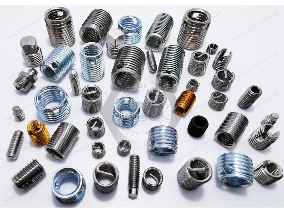
Relevant inspection characteristics may include:
internal thread;
outside diameter;
overall length;
cutting feature geometry;
material;
surface finish;
dimensional tolerances;
visual condition;
packaging condition.
Internal thread inspection can include GO/NO-GO thread gauges where appropriate to the specified thread system.
Application validation should be distinguished from dimensional inspection.
A dimensionally conforming insert can still perform poorly if the parent-material hole or installation process is incorrect.
For faster technical review and quotation, provide as much of the following information as possible:
internal thread size;
thread pitch;
metric or Unified inch thread requirement;
insert type or reference series;
insert dimensions;
parent material;
parent-material grade if known;
pilot-hole diameter;
boss or wall geometry where critical;
insert material;
surface finish;
required pull-out performance, if specified;
required torque-out performance, if specified;
corrosion requirement, if applicable;
operating environment;
drawing or existing part specification;
2D or 3D file for custom requirements;
sample quantity;
production order quantity;
estimated annual demand;
packaging requirements;
material documentation requirements;
traceability requirements;
target application.
If you are replacing an existing insert but do not know the complete specification, send the existing drawing,
dimensional data, or sample information for engineering review.
Normally, no. Their principal feature is that the external geometry creates its own engagement during installation into a correctly prepared pilot hole.
The pilot hole itself remains a critical controlled dimension.
Yes, aluminum is a common application, but the correct insert and pilot hole depend on the specific aluminum alloy, component geometry, load, and installation conditions.
They can be used in suitable engineering plastics. Polymer type, reinforcement, boss dimensions, pilot-hole size, temperature, creep,
and installation stress should be considered before production release.
Yes, in many cases. The damaged hole must still leave enough sound parent material for the insert's external geometry to engage.
Severe damage may require a different repair size or another repair strategy.
Use the insert geometry and parent material as the starting point. The hole must provide sufficient external engagement without generating excessive installation stress.
For critical applications, confirm the final diameter through component-level testing.
Common causes include an oversized pilot hole, insufficient engagement, unsuitable parent material, incorrect insert selection, installation damage, or mating-screw torque beyond the validated condition.
The insert can provide a stable threaded anchor, but it does not by itself guarantee that the mating screw will resist vibration loosening.
Joint preload, friction, transverse movement, locking method, screw properties, and assembly conditions must also be evaluated.
Pull-out is axial extraction of the insert from the parent material. Torque-out is rotation of the insert in the parent material.
They are different failure modes and may require different design and validation considerations.
The choice depends on mechanical requirements, corrosion environment, parent material, coating requirements, cost, and assembly conditions.
Stainless steel may provide better corrosion resistance in appropriate environments, while coated steel can be a practical solution for many industrial applications.
At minimum, provide the internal thread, insert dimensions or reference geometry, material, finish, quantity, and application.
Parent material, pilot-hole information, drawings, mechanical requirements, and annual demand help the supplier evaluate the requirement more accurately.
For engineers and sourcing teams evaluating alternative thread-reinforcement technologies, related JUXIN FASTENERS content can include:
Related Engineering Guide: Wire Thread Inserts and Helical Thread Repair
Related Guide: Threaded Inserts for Aluminum Components
Related Guide: Threaded Inserts for Engineering Plastics
Related Engineering Guide: Stainless Steel Fastener Galling Prevention
Related Product: Heat-Set Inserts for Thermoplastic Components
Related Solution: Drawing-Based Custom Fasteners and CNC Machined Components
These internal links should connect thread-reinforcement selection, installation engineering, material selection, failure prevention,
and procurement requirements rather than simply linking unrelated fastener pages.
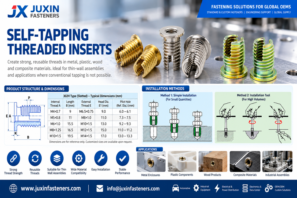
A reliable self-tapping insert program starts with the parent material and joint requirements—not simply with a catalog part number.
JUXIN FASTENERS supports industrial customers requiring self-tapping threaded inserts, thread repair inserts, stainless steel threaded inserts,
and drawing-based fastening components for OEM and engineered applications.
For new designs, engineers can provide the parent material, internal thread, component geometry, expected loading, and installation conditions for technical review.
For procurement and supplier-development projects, provide the existing part drawing, specification, sample requirements, estimated annual demand,
and required documentation so that dimensional, material, finish, inspection, and production requirements can be evaluated before quotation.
Email: info@juxinfasteners.com
Website: www.juxinfasteners.com
Contact Us
Tel.:
+86 020 8621 0320
+86 020 3121 6067
E-mail:
Technical Support:
Navigation
SEND INQUIREY