Call Us
+86 136 6007 9809
Call Us
+86 136 6007 9809

Nov. 20, 2023
Self tapping thread inserts create reusable internal machine threads in parent materials where directly tapped or molded threads may not provide the required durability, service life, or load distribution.
They are commonly considered for suitable engineering plastics, aluminum alloys, magnesium alloys, cast components, and other materials where thread reinforcement is required.
Unlike insert systems that require a specially pre-tapped receiving thread, a self tapping thread insert is installed into a correctly prepared pilot hole.
Its external cutting or forming geometry establishes engagement with the parent material while its internal thread provides the fastening interface for a machine screw or bolt.
For engineers, however, successful insert selection requires much more than choosing an internal thread size.
The performance of the final threaded joint depends on:
parent material;
insert geometry;
pilot-hole diameter;
insert engagement length;
boss diameter;
wall thickness;
edge distance;
installation torque;
installation alignment;
mating screw torque;
environmental exposure;
required pull-out and torque-out performance.
JUXIN FASTENERS supplies self tapping thread inserts and related threaded insert solutions for industrial OEM, machinery, automotive, electrical equipment,
electronics, automation, transportation, and other engineered applications.
This guide focuses on the engineering decisions that determine whether a self tapping insert is appropriate, how different parent materials affect selection,
and what procurement teams should specify when qualifying an industrial threaded insert supplier.
A self tapping thread insert is a solid threaded insert with an internal machine thread and an external self-tapping geometry.
It is installed into a prepared pilot hole without requiring the parent material to be pre-tapped with the insert's external thread.
During installation, the external cutting or forming features establish mechanical engagement with the surrounding material.
After installation, the internal thread accepts a standard mating screw or bolt of the specified thread system.
Self tapping thread inserts are primarily used for:
reinforcing threads in lower-strength materials;
creating durable reusable internal threads;
improving resistance to parent-thread wear;
repairing damaged threaded holes;
supporting repeated assembly and maintenance;
transferring threaded-joint loads through a larger parent-material engagement area.
They may also be described as:
self tapping inserts;
self tapping threaded inserts;
self tapping screw inserts;
thread reinforcement inserts;
threaded inserts for plastic;
threaded inserts for aluminum;
solid threaded inserts;
thread repair inserts.
Because terminology varies between suppliers, drawings should define the required geometry and dimensions rather than relying only on a product name.
Self tapping inserts are particularly useful when the parent material itself is the limiting factor in the threaded connection.
A practical decision path is:
Parent Material → Required Thread Life → Mechanical Load → Available Material Around the Hole → Insert Geometry → Pilot Hole → Installation Process → Validation
Consider a self tapping insert when:
direct threads strip at the required tightening load;
screws must be removed and reinstalled repeatedly;
a polymer or lightweight alloy requires a durable metal thread;
damaged internal threads must be repaired;
a reusable service connection is required;
the design benefits from eliminating a separate parent-material tapping operation;
the original material cannot provide sufficient thread engagement for the required service condition.
Do not automatically specify a self tapping insert simply because the parent material is aluminum or plastic.
For lightly loaded joints assembled only once, a direct thread may remain the simpler and more economical solution.
The basic installation sequence is straightforward:
A pilot hole is drilled, molded, cast, or otherwise prepared.
The insert is aligned with the hole axis.
A suitable installation tool drives the insert into the component.
The external cutting or forming features engage the parent material.
The insert reaches its specified installation depth.
The installation tool is removed.
The internal thread is inspected and becomes the reusable fastening interface.
The engineering principle is important: the insert transfers load from the mating screw through the insert body into a larger surrounding area of the parent material.
This can provide a more durable threaded interface than a direct thread in suitable lower-strength materials.
However, the insert cannot compensate for inadequate parent-material volume.
If the boss is too small, the wall is too thin, or the insert is positioned too close to an edge, installation stresses or service loads can damage the component.
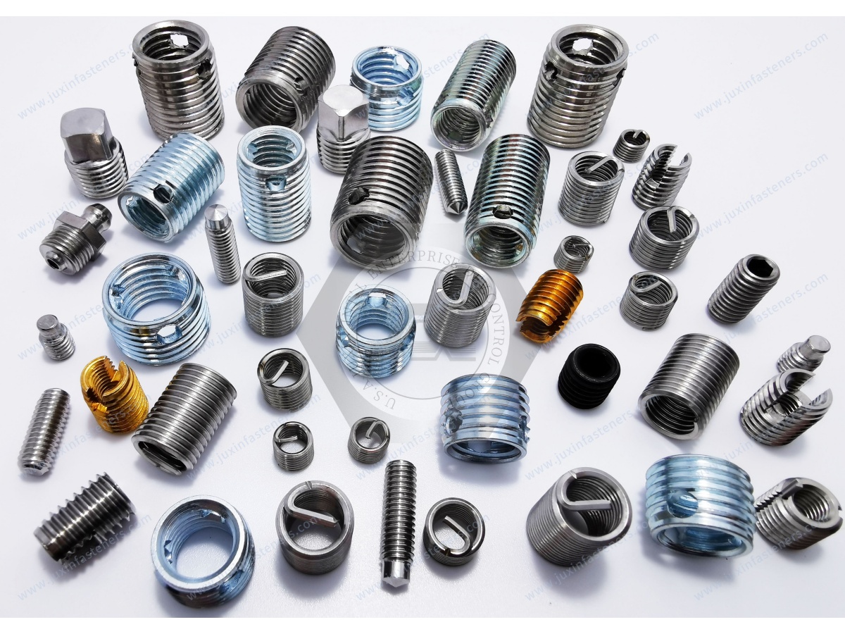
“Threaded insert” describes a broad family of fastening products.
Different insert technologies solve different manufacturing problems.
| Insert Technology | Typical Installation Principle | Common Engineering Use |
|---|---|---|
| Self tapping thread insert | Creates its own external engagement in a pilot hole | Thread reinforcement and repair in suitable plastics, aluminum, castings and other materials |
| Heat-set insert | Installed into thermoplastic using controlled heat | Molded thermoplastic components |
| Ultrasonic insert | Installed using ultrasonic energy | Suitable thermoplastic assemblies |
| Helical wire insert | Installed into a specially prepared tapped hole | Thread reinforcement and repair |
| Rivet nut | Mechanically deforms to clamp thin sheet or hollow structure | One-side-access sheet-metal assemblies |
| Self-clinching nut | Pressed into suitable ductile sheet | Thin-sheet production assemblies |
The correct insert therefore depends on the parent material and assembly architecture, not simply on the desired internal thread.
Some product descriptions broadly claim that self tapping thread inserts are suitable for “thin metal.”
That statement requires qualification.
A conventional self tapping solid insert needs sufficient surrounding material for its external geometry to engage and transfer load.
Very thin sheet may not provide enough engagement length or surrounding material.
For thin sheet metal, engineers should often compare alternatives such as:
blind rivet nuts for one-side-access assemblies;
hex rivet nuts where stronger mechanical anti-rotation is required;
self-clinching nuts where the sheet material, hardness, thickness, and press process are suitable;
weld nuts where welding is compatible with the manufacturing process.
Related Engineering Guide: Rivet Nut vs Self-Clinching Nut
This distinction prevents a common selection mistake: choosing an insert based only on the required internal thread without considering how the fastener transfers load into the parent structure.
Engineering plastics are one of the most important application groups for threaded inserts, but not every polymer behaves the same way.
Selection should consider:
polymer family;
filled or unfilled resin;
glass-fiber content;
material stiffness;
brittleness;
creep behavior;
operating temperature;
molded boss geometry;
repeated assembly cycles;
required screw torque.
For example, an unfilled PA66 component and a heavily glass-filled PA66 component can respond very differently during insert installation.
A more rigid or brittle material may require greater attention to pilot-hole diameter and boss geometry because excessive radial installation stress can cause cracking.
For thermoplastic components, engineers often compare self tapping inserts with heat-set inserts.
May be considered when:
mechanical installation is preferred;
heating equipment is undesirable;
the parent material can accommodate the installation stresses;
repair or field installation is required.
May be considered when:
the component is a suitable thermoplastic;
controlled thermal installation is available;
the insert geometry is designed to embed into softened polymer;
high-volume molded-component assembly is required.
Neither method is universally superior.
The decision should consider:
Polymer → Boss Geometry → Assembly Volume → Mechanical Load → Installation Equipment → Service Temperature → Validation
Related Product: Heat-Set Inserts for Thermoplastic Components
Aluminum housings and structural components are another major application.
Potential uses include:
machinery housings;
power electronic enclosures;
automation components;
transmission housings;
electrical equipment;
thermal-management components;
instrumentation;
lightweight structural assemblies.
The term “aluminum,” however, is not sufficiently precise for critical insert selection.
Relevant variables include:
aluminum alloy;
cast or wrought condition;
material hardness;
casting quality;
porosity;
wall thickness;
pilot-hole quality;
required pull-out load;
required tightening torque.
An insert configuration validated in a relatively soft casting should not automatically be assumed to perform identically in a higher-strength wrought alloy.
Magnesium and other lightweight alloys can also require reinforced internal threads.
In these assemblies, engineers should consider both mechanical performance and material compatibility.
Where dissimilar metals are exposed to moisture or another electrolyte, galvanic corrosion may become a concern.
The evaluation should consider:
insert material;
parent material;
surface treatment;
exposed area ratio;
environmental exposure;
drainage;
service life;
coating damage during installation.
Corrosion protection should therefore be evaluated at the complete assembly level.
Wood threaded inserts are an established fastener category, but they should not automatically be treated as identical to self tapping inserts engineered for aluminum or industrial plastics.
Solid wood, MDF, particleboard, plywood, and engineered wood products have very different mechanical structures from metals and engineering polymers.
Threaded inserts intended for furniture or wood assemblies may use:
coarse external threads;
specialized drive features;
flanged geometries;
external profiles optimized for wood fibers.
If a project requires threaded inserts for wood, the insert geometry should be selected specifically for the substrate.
Industrial sourcing teams should therefore avoid assuming that one self tapping insert design is universally suitable for aluminum, plastic, and wood.
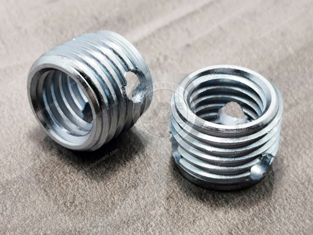
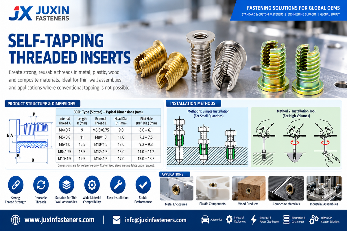
A common self tapping insert configuration uses a cutting slot near the installation end.
The slot provides cutting edges that help the insert create its external engagement during installation.
Depending on the specific insert design and parent material, slotted inserts can be considered for:
aluminum alloys;
selected plastics;
non-ferrous materials;
suitable cast components.
When cross-referencing a slotted insert from another supplier, compare the actual dimensions rather than assuming equivalent appearance means equivalent performance.
Important characteristics include:
internal thread;
external thread;
overall length;
outside diameter;
cutting-slot geometry;
installation end;
material;
finish;
recommended pilot hole.
Another common design uses cutting holes or cutting openings instead of a single slot.
Certain product families are commonly referenced using series designations such as 307/308-style inserts.
However, supplier-specific series numbers should not substitute for an engineering drawing.
When qualifying an alternative source, procurement teams should compare:
complete dimensional geometry;
internal thread;
external thread profile;
cutting features;
length;
material;
finish;
pilot-hole recommendation;
installation method;
mechanical requirements.
This is particularly important in second-source qualification because two inserts carrying similar descriptive names may not be dimensionally interchangeable.
The insert material must satisfy both manufacturing and service requirements.
Steel inserts can provide a practical combination of mechanical strength, machinability, wear resistance, and cost.
Depending on the product design and customer requirements, surface protection can include zinc-based coatings or other specified finishes.
Steel inserts are commonly considered for general industrial applications involving suitable:
aluminum components;
plastic components;
machinery;
electrical equipment;
industrial housings.
Surface treatment should be selected according to the required corrosion environment rather than appearance alone.
Stainless steel inserts may be considered where corrosion resistance is important.
Depending on the specific insert geometry and customer specification, stainless grades may include 303, 304, 316, or other appropriate grades.
The material should be specified according to the actual environment.
Stainless steel is not automatically immune to:
galvanic corrosion;
crevice corrosion;
contamination;
thread galling;
aggressive chemical environments.
Brass inserts are widely associated with threaded insert applications, particularly in plastics and electrical components.
However, material availability depends on the required insert geometry.
Engineers should select brass because its mechanical, electrical, corrosion, or manufacturing characteristics match the application—not simply because the parent component is plastic.
The pilot hole is one of the most important dimensions in a self tapping insert assembly.
It affects:
installation torque;
external thread engagement;
radial stress;
pull-out performance;
torque-out behavior;
component cracking risk;
installation consistency.
Potential consequences include:
excessive installation torque;
tool overload;
insert damage;
boss expansion;
parent-material cracking;
difficult installation;
misalignment.
Potential consequences include:
reduced external engagement;
insert rotation;
reduced pull-out resistance;
reduced torque-out resistance;
inconsistent installed position.
The optimum pilot hole therefore depends on both insert geometry and parent material.
For production programs, actual component testing is more meaningful than relying solely on a generic pilot-hole table.
Pilot-hole diameter alone does not determine whether the installation is safe.
The material surrounding the hole must withstand:
radial installation forces;
axial service loads;
screw tightening forces;
environmental stresses;
repeated assembly.
If an insert is installed in a molded boss, engineers should evaluate the boss outside diameter and surrounding wall.
If the hole is near a component edge, insufficient edge distance may allow cracking or breakout.
A useful design sequence is:
Insert Outside Diameter → Required Parent-Material Engagement → Boss/Wall Geometry → Pilot Hole → Installation Validation
This is particularly important for brittle polymers, cast components, and compact lightweight designs.
Insert performance is often described simply as “strong,” but engineering validation should distinguish different failure modes.
Pull-out resistance describes the ability of the installed insert to resist axial extraction from the parent material.
It is influenced by:
insert engagement length;
external thread geometry;
parent-material strength;
pilot-hole diameter;
surrounding material;
installation quality.
Torque-out describes resistance to rotation of the insert within the parent material.
It is influenced by:
external geometry;
cutting features;
parent material;
pilot-hole condition;
engagement length;
installation quality;
applied screw torque.
A design can perform well in one load mode and less effectively in another.
Critical applications should therefore define the actual required mechanical performance rather than using a generic requirement such as “high strength.”
Not necessarily.
The insert can provide a durable threaded anchor in the parent material, but vibration loosening of the mating screw is a separate joint-engineering issue.
Screw loosening can depend on:
preload;
tightening method;
friction;
transverse movement;
joint stiffness;
bearing surfaces;
screw properties;
locking features;
thermal cycling;
service vibration.
If vibration loosening is a concern, engineers should evaluate the complete bolted joint and select an appropriate locking strategy where necessary.
The insert's role is primarily to provide a stable threaded interface in the parent component.
Possible causes:
pilot hole too large;
insufficient external engagement;
parent material too weak;
unsuitable insert geometry;
excessive mating-screw torque;
damaged installation.
Possible causes:
pilot hole too small;
boss diameter too small;
insufficient edge distance;
brittle parent material;
excessive installation torque;
unsuitable insert design.
Possible causes:
poor starting alignment;
unsuitable tooling;
excessive installation speed;
inconsistent pilot-hole geometry.
Angular installation can affect screw alignment and may introduce undesirable stress into the assembly.
Potential causes include:
insufficient engagement length;
oversized pilot hole;
inadequate parent-material strength;
insufficient surrounding material;
service load above the validated condition.
Possible causes:
installation-tool damage;
contamination;
chips;
cross-threading;
incorrect mating screw;
excessive tightening torque.
Understanding these failure modes allows engineers to improve the component and assembly process before mass production.
A controlled installation process should normally include the following steps.
Avoid specifications that state only:
plastic;
aluminum;
casting.
Where important, identify the actual material grade or resin system.
Define:
diameter;
tolerance;
depth;
blind or through condition;
entrance geometry where required.
Check:
boss diameter;
wall thickness;
edge distance;
material below a blind hole;
available insert depth.
Depending on the insert and production environment, installation may use dedicated manual, pneumatic, electric, or automated tooling.
The tool should maintain appropriate:
alignment;
driving engagement;
installation depth;
process control.
A general-purpose screwdriver or drill should not automatically be assumed to provide a controlled production installation process.
Relevant checks may include:
installed depth;
perpendicularity;
internal thread condition;
component cracking;
surface damage;
insert rotation.
Potential applications include suitable:
aluminum housings;
polymer components;
electronic control housings;
thermal-management components;
interior assemblies;
lightweight equipment structures.
Automotive suitability should be determined by the component drawing, load requirements, environmental conditions, customer specifications, and validation plan.
Thread inserts may be used in:
aluminum electrical housings;
power electronics;
converter and inverter enclosures;
control equipment;
switchgear-related assemblies;
thermal-management hardware.
The fastening design should consider electrical requirements where the insert affects grounding, isolation, or enclosure architecture.
Applications can include:
machine housings;
actuator components;
robotic equipment;
automation systems;
equipment covers;
fixtures;
service-access components.
Repeated maintenance makes thread durability particularly important in this sector.
Potential applications include:
electronic housings;
communication equipment;
instrumentation;
server-related equipment;
control systems.
Where plastic housings are used, insert technology should be selected according to the actual polymer and assembly process.
Selected rail equipment, housings, interior components, and mechanical assemblies may use reinforced threaded connections.
Rail applications should be evaluated against the actual component requirements, including structural role, vibration,
environmental exposure, maintenance, material requirements, and customer specifications.
A good engineering supplier should also recognize when a self tapping insert may not be the most suitable solution.
Consider another technology when:
very thin sheet requires a threaded connection: evaluate rivet nuts or self-clinching fasteners;
a thermoplastic component is optimized for thermal installation: evaluate heat-set or ultrasonic inserts;
a specially tapped hole is acceptable and a lightweight thread reinforcement system is preferred: evaluate helical wire inserts;
one-side access is required in a hollow structure: evaluate blind rivet nuts;
suitable sheet and press equipment are available: evaluate self-clinching nuts or studs;
a welded threaded attachment is appropriate: evaluate weld nuts or weld studs.
This comparison helps engineers select the fastening architecture rather than forcing one product into every application.
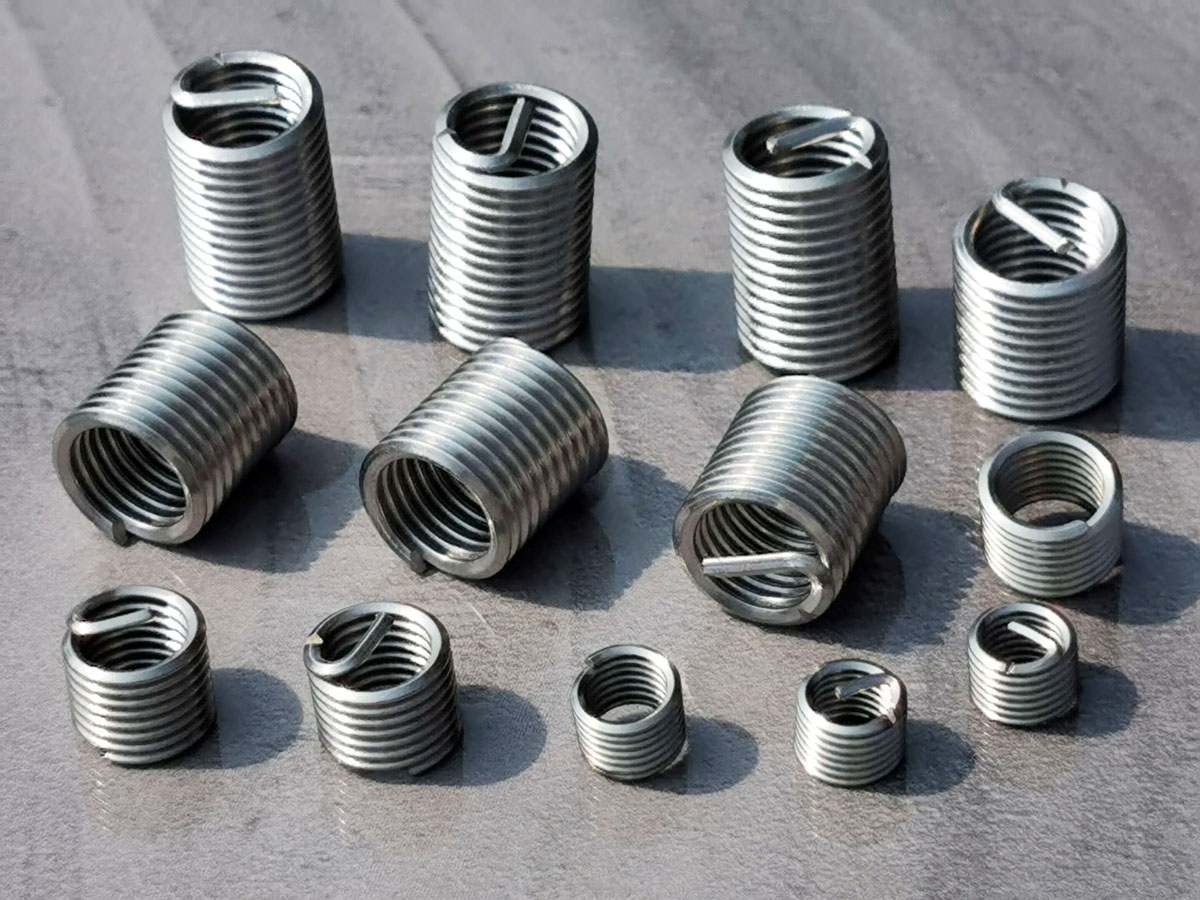
Before specifying a self tapping thread insert, confirm:
What is the exact parent material?
What internal thread is required?
How many assembly and disassembly cycles are expected?
What screw tightening torque will be used?
What axial load must the insert withstand?
Is torque-out performance important?
What boss diameter or wall thickness is available?
What edge distance is available?
Is the hole blind or through?
What installation equipment will be used?
What corrosion environment is expected?
Is the insert part of an electrical interface?
Is field repair required?
What validation testing is required?
These questions are more useful than selecting an insert solely from nominal thread size.
Depending on the application, an engineering drawing or specification may include:
internal thread size;
thread pitch;
insert style;
outside diameter;
overall length;
external geometry;
insert material;
surface finish;
parent material;
pilot-hole diameter;
hole tolerance;
hole depth;
installed position;
required pull-out performance;
required torque-out performance;
corrosion requirements;
inspection requirements.
Where the project involves replacing an existing insert, provide the original drawing or dimensional specification whenever possible.
For industrial production, relevant inspection characteristics may include:
internal thread;
external dimensions;
overall length;
cutting geometry;
material;
surface finish;
visual condition;
packaging.
Internal machine threads may be inspected with appropriate GO/NO-GO thread gauges according to the specified thread system.
Dimensional inspection and application validation should not be confused.
An insert can meet dimensional requirements and still fail in the customer's component if the pilot hole, parent material, or installation process is incorrect.
Procurement teams sourcing self tapping inserts should evaluate more than unit price.
For OEM, Tier-1/Tier-2, industrial machinery, electrical equipment, and engineered-component programs, supplier evaluation may include:
drawing review capability;
dimensional inspection;
thread-gauge inspection;
material specification control;
surface-treatment control;
sample qualification;
customer-specified first article requirements;
approved sample or Golden Sample control where required;
lot traceability;
packaging requirements;
engineering change control;
prototype-to-production consistency.
For second-source development, dimensional interchangeability should be confirmed before replacing an existing insert.
A similar-looking insert is not automatically a technically equivalent insert.
For an efficient technical review and quotation, provide:
internal thread size;
thread pitch;
metric or Unified inch thread;
insert style;
reference part number, if applicable;
dimensional drawing;
insert material;
surface finish;
parent material;
parent-material grade or resin, where known;
pilot-hole diameter;
hole depth;
boss or wall dimensions where critical;
required pull-out load, if specified;
required torque-out value, if specified;
operating environment;
corrosion requirements;
installation method;
sample quantity;
order quantity;
estimated annual demand;
required material documentation;
traceability requirements;
packaging requirements;
2D or 3D files for drawing-based requirements.
For existing-part replacement projects, providing the current drawing or a complete dimensional specification can significantly reduce cross-reference risk.
Normally, no. Their external geometry creates its own engagement in a correctly prepared pilot hole. The hole diameter and parent material still need to be controlled.
Yes, for suitable polymers and component geometries. Polymer type, reinforcement, boss dimensions, pilot-hole diameter, creep, temperature, and installation stress should be evaluated.
Yes. Aluminum is a common parent material, but alloy, hardness, casting condition, pilot hole, surrounding material, and required load affect selection.
Conventional solid self tapping inserts require sufficient material for external engagement. For genuinely thin sheet, rivet nuts or self-clinching fasteners may be more appropriate depending on access, sheet material, thickness, and production process.
A self tapping insert creates external engagement within a prepared hole in a material with sufficient thickness.
A rivet nut mechanically deforms to clamp onto sheet or a hollow structure and can normally be installed from one side.
A self tapping insert mechanically establishes its external engagement. A heat-set insert is installed into suitable thermoplastic by using controlled heat to soften the surrounding polymer.
They can be used for many thread-repair applications if sufficient sound parent material remains around the damaged hole. The remaining hole size and available wall thickness must be evaluated.
Common reasons include an undersized pilot hole, inadequate boss diameter, insufficient edge distance, brittle material, excessive installation torque, or an unsuitable insert geometry.
Possible causes include an oversized pilot hole, insufficient engagement, unsuitable parent material, installation damage, or mating-screw torque above the validated condition.
Not automatically. The insert provides the threaded anchor, while vibration loosening of the mating screw depends on the complete bolted joint,
including preload, friction, transverse movement, joint stiffness, and any locking method.
Consider mechanical requirements, parent material, corrosion environment, surface treatment, temperature, mating materials, and cost.
Stainless steel can improve corrosion resistance in appropriate environments but is not automatically the best material for every assembly.
Relevant internal links for this topic should connect the reader to the next engineering decision rather than unrelated product pages:
Related Guide: Tapping Inserts for Soft Metal and Aluminum
Related Product: Heat-Set Inserts for Thermoplastics
Related Engineering Guide: Wire Thread Inserts and Thread Repair
Related Comparison: Rivet Nut vs Self-Clinching Nut
Related Product: Blind Rivet Nuts for Thin Sheet and Hollow Structures
Related Product: Self-Clinching Nuts, Studs and Standoffs
Related Guide: Stainless Steel Fastener Galling Prevention
Related Solution: Drawing-Based Custom Fasteners and CNC Machined Components
Actual internal URLs should use the existing indexed JUXIN FASTENERS pages.
Successful threaded-insert selection begins with the parent material and assembly requirement rather than a catalog part number.
JUXIN FASTENERS supports industrial customers sourcing self tapping thread inserts, thread repair inserts, heat-set inserts,
wire thread inserts, rivet nuts, self-clinching fasteners, and drawing-based fastening components.
For engineering projects, provide the parent material, required internal thread, component geometry, pilot-hole condition, mechanical requirements, installation method, and operating environment.
For procurement, strategic sourcing, and supplier-development projects, provide the existing drawing or specification, required material and finish,
sample quantity, production volume, annual demand, inspection requirements, documentation requirements, and packaging requirements.
This allows the fastening solution to be reviewed from both an engineering and supply-chain perspective before quotation and sample qualification.
Email: info@juxinfasteners.com
Website: www.juxinfasteners.com
Contact Us
Tel.:
+86 020 8621 0320
+86 020 3121 6067
E-mail:
Technical Support:
Navigation
SEND INQUIREY