
Call Us
+86 136 6007 9809
Call Us
+86 136 6007 9809

Oct. 31, 2024
Stainless Steel Cup Point Set Screws: DIN 916 / ISO 4029 for Shaft and Component Locking
Stainless steel cup point set screws are compact, headless threaded fasteners used to position and secure mechanical components in suitable shaft and hub assemblies.
They are commonly used in shaft collars, pulleys, gears, couplings,
adjustment mechanisms and industrial equipment where a conventional bolt head would create interference or require additional installation space.
The cup point has a concave end with a circular contact edge. When tightened against a mating surface,
this geometry can develop local mechanical engagement and resistance to relative movement.
However, reliable shaft locking depends on more than the screw material or nominal diameter.
The contact surface, shaft hardness, tightening torque, thread engagement, point geometry and operating loads all affect performance.
For mechanical engineers, the main considerations include shaft damage, holding force, torque transmission and joint reliability.
For manufacturing engineers and production managers, controlled installation torque, hex socket quality, tooling access and repeatable assembly are essential.
For procurement and supplier development teams, accurate identification of the point type and dimensional standard is critical when sourcing replacement set screws or qualifying OEM suppliers.
Juxin Fasteners supplies stainless steel cup point set screws and drawing-specific industrial fastening components for OEM applications.
What Is a Stainless Steel Cup Point Set Screw?
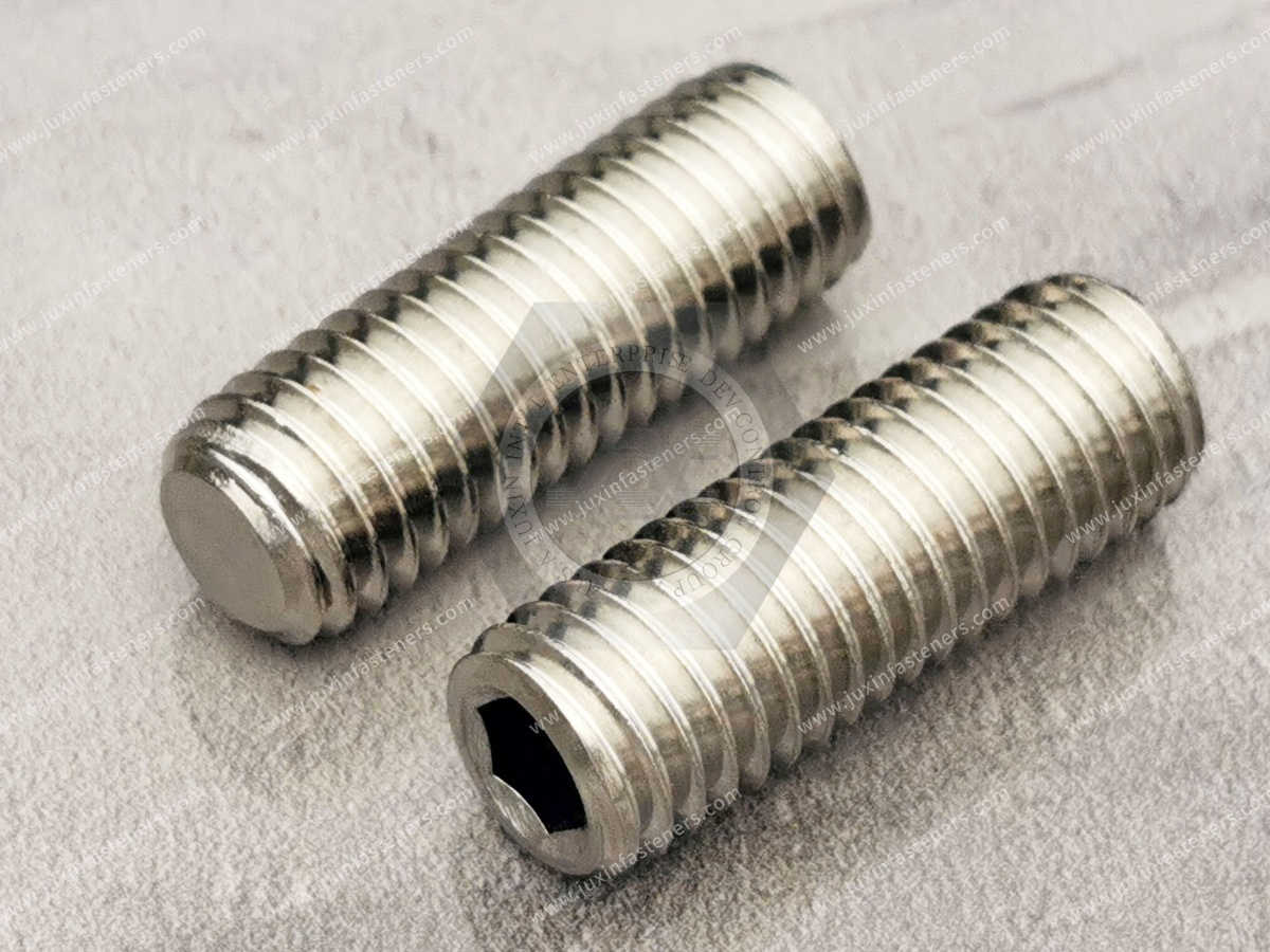
A cup point set screw is a headless threaded fastener with a concave contact end.
It is typically installed using an internal hex drive.
The screw is threaded into a component such as a shaft collar or hub.
When tightened, the cup point contacts the shaft or mating component.
The resulting normal force and local contact geometry help resist relative movement.
Typical Applications
Shaft collars
Pulleys
Gear hubs
Couplings
Adjustment mechanisms
Machine components
Automation equipment
Important Limitation
A cup point set screw does not automatically provide a positive mechanical lock against every axial or rotational load.
The complete assembly must be evaluated.
DIN 916 / ISO 4029: Correct Standards for Cup Point Set Screws
A critical distinction in set screw selection is the relationship between point geometry and dimensional standards.
DIN 916 / ISO 4029
These standards are associated with hexagon socket set screws with cup points.
DIN 913 / ISO 4026
These standards are associated with hexagon socket set screws with flat points.
DIN 914 / ISO 4027
These standards are associated with hexagon socket set screws with cone points.
DIN 915 / ISO 4028
These standards are associated with hexagon socket set screws with dog points.
Comparison Table
| Point style | Common DIN reference | ISO reference | Main selection consideration |
|---|---|---|---|
| Flat point | DIN 913 | ISO 4026 | Reduced localized penetration in suitable contacts |
| Cone point | DIN 914 | ISO 4027 | Concentrated contact and potential surface indentation |
| Dog point | DIN 915 | ISO 4028 | Engagement with a suitable locating hole or recess |
| Cup point | DIN 916 | ISO 4029 | Circular contact edge and local shaft engagement |
Engineering Recommendation
Do not substitute DIN 913 flat point screws for DIN 916 cup point screws without reviewing the joint design.
The point geometries are functionally different.
How Cup Point Set Screws Hold a Shaft
The cup point applies force to a localized area of the shaft surface.
The contact may produce elastic deformation, plastic indentation or a combination of both.
The resulting holding behavior depends on the shaft material and surface condition.
Main Factors Affecting Holding Performance
Set screw diameter
Screw material and hardness
Cup point geometry
Tightening torque
Shaft material
Shaft hardness
Surface finish
Contact position
Hub stiffness
Operating loads
Important Distinction
The holding capacity of a cup point set screw cannot be determined from nominal screw diameter alone.
Cup Point Contact Mechanics
The cup point's annular contact edge can create localized pressure.
On a relatively soft shaft, the edge may indent the surface.
This indentation can contribute to resistance against relative movement.
On a harder shaft, the contact behavior may be different.
Engineering Considerations
Evaluate:
Local contact pressure
Shaft surface damage
Resistance to axial movement
Resistance to rotation
Repeated loading
Potential fretting
Serviceability
Engineering Recommendation
Where shaft surface preservation is critical, compare cup point screws with alternative point styles or other shaft-locking methods.
Cup Point Set Screws and Shaft Hardness
Shaft hardness affects how the cup point contacts the surface.
Softer Shaft Materials
A cup point may create more pronounced indentation.
Potential concerns include:
Permanent shaft marks
Local deformation
Difficulty repositioning components
Reduced surface quality
Harder Shaft Materials
The point may produce less indentation, changing the balance between frictional and mechanical engagement.
Engineering Recommendation
Do not assume that a harder shaft always provides better cup point holding performance.
The complete contact system must be evaluated.
Shaft Collars and Set Screw Locking
Shaft collars are commonly used for axial positioning and mechanical stops.
A cup point set screw may be used to secure the collar to the shaft.
Design Considerations
Shaft diameter
Collar material
Thread engagement
Screw position
Axial loading
Shaft surface condition
Installation torque
Important Limitation
For applications requiring frequent repositioning or minimal shaft damage, a clamping-style shaft collar may be preferable.
Pulley and Gear Hub Applications
Cup point set screws may be used to retain selected pulleys and gear hubs.
Potential Applications
Light-duty pulley positioning
Auxiliary gear assemblies
Mechanical adjustment systems
Equipment drive components
Engineering Considerations
Torque transmission
Shaft diameter
Hub length
Number of set screws
Screw angular position
Dynamic loading
Shaft surface damage
Important Limitation
A set screw alone may not be suitable for transmitting high torque or resisting severe shock loads.
Alternative methods may include keys, splines, interference fits or engineered clamping connections.
Engineering Recommendation
Select the shaft-hub connection based on required torque and operating conditions rather than treating cup point set screws as universal shaft-locking devices.
18-8 Stainless Steel Cup Point Set Screws
18-8 stainless steel is commonly associated with austenitic stainless steel compositions such as 304-type materials.
Potential advantages include:
General atmospheric corrosion resistance
Suitability for selected industrial environments
Compatibility with certain precision equipment
Non-threaded-head-free installation geometry
Important Material Consideration
18-8 is a broad commercial description.
For OEM production, the exact stainless steel grade and applicable mechanical requirements should be specified.
A2 Stainless Steel Cup Point Set Screws
A2 is a stainless steel designation used in the ISO fastener material classification system.
A2 materials are commonly associated with 304-type austenitic stainless steels.
However, the exact material and mechanical property class must be confirmed.
316 Stainless Steel Cup Point Set Screws
316 stainless steel generally provides improved resistance to certain chloride-containing environments compared with 304-type stainless steel.
Potential applications include:
Selected coastal equipment
Outdoor machinery
Certain chemical processing environments
Corrosion-sensitive industrial assemblies
Important Limitation
316 stainless steel is not completely immune to crevice corrosion or chloride attack.
A4 Stainless Steel Cup Point Set Screws
A4 is commonly associated with molybdenum-containing austenitic stainless steel materials such as 316-type compositions.
The applicable material and mechanical requirements should be specified.
Carbon Steel Cup Point Set Screws
Carbon or alloy steel set screws may be selected where hardness, mechanical performance and cost are important.
Depending on the product specification, steel set screws may provide different point-hardness characteristics from austenitic stainless steel versions.
Engineering Recommendation
Do not assume that stainless steel and hardened alloy steel set screws provide identical indentation or holding behavior.
Material Comparison
| Material | Typical selection consideration | Important limitation |
|---|---|---|
| A2 / 304-type stainless steel | General corrosion resistance | Mechanical and point-hardness characteristics |
| A4 / 316-type stainless steel | Improved resistance in some chloride environments | Cost and localized corrosion |
| Carbon or alloy steel | Hardness and mechanical performance options | Corrosion protection may be required |
Mechanical Properties of Stainless Steel Set Screws
The mechanical performance of stainless steel set screws depends on:
Material grade
Manufacturing process
Material condition
Applicable mechanical property class
Product dimensions
Important Distinction
A single generic tensile-strength or yield-strength value should not be applied to every stainless steel cup point set screw.
For stainless steel fasteners, ISO 3506-3 is relevant to mechanical properties of applicable set screws and similar fasteners under its defined scope.
Engineering Recommendation
Specify the applicable mechanical property requirements and obtain supporting documentation where necessary.
Metric Cup Point Set Screw Dimensions
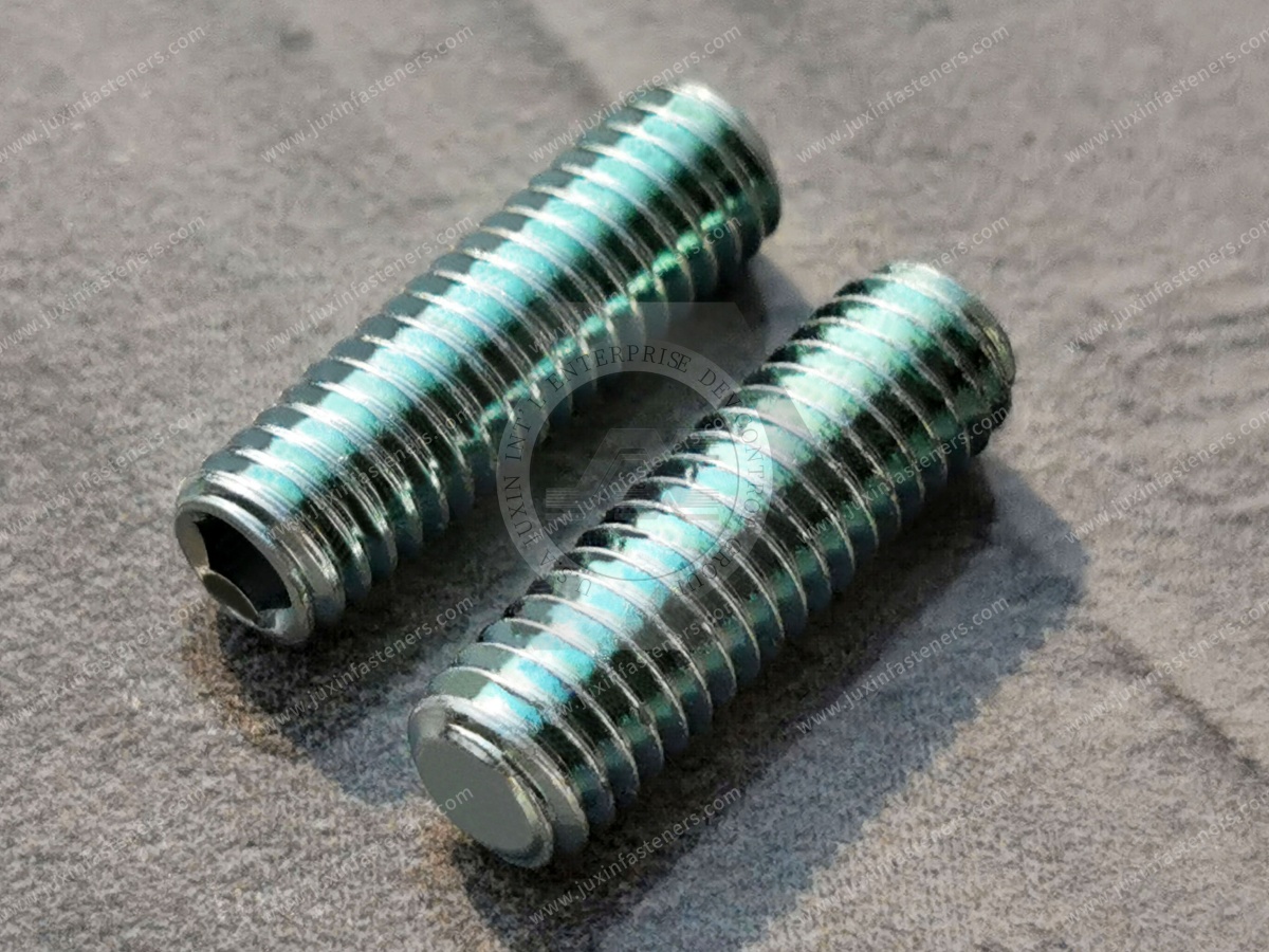
Metric cup point set screws are commonly specified using an M designation.
Examples include:
M3
M4
M5
M6
M8
M10
M12
These are examples of metric thread designations, not a statement of current stock or complete manufacturing range.
Metric Thread Requirements
The thread must be specified according to the applicable metric thread standard and tolerance requirements.
ISO metric threads are not directly interchangeable with UNC, UNF, BSW or BSF threads.
Inch-Series Cup Point Set Screws
Inch-series socket set screws may be specified using UNC or UNF threads and applicable ASME dimensional requirements.
Important Distinction
A metric DIN 916 / ISO 4029 set screw should not be substituted for an inch-series set screw solely because the nominal diameter appears similar.
Engineering Recommendation
Confirm thread designation, pitch, tolerance, length, drive dimensions and point geometry before approving any alternative.
Cup Point Set Screw Length and Thread Engagement
Set screw length affects thread engagement and tool access.
Insufficient Engagement
Possible consequences include:
Thread stripping
Reduced tightening capacity
Poor alignment
Assembly instability
Excessive Length
Possible consequences include:
Interference with surrounding components
Unwanted protrusion
Assembly access problems
Engineering Recommendation
Determine the required thread engagement according to the hub material, thread strength and installation torque.
Hex Socket Drive Selection
Cup point set screws commonly use an internal hex drive.
The hex socket allows installation without a protruding external head.
Potential Advantages
Compact assembly
Tool access in confined spaces
Compatibility with manual and powered hex tools
Common Problems
Socket rounding
Incorrect driver size
Misalignment
Excessive installation torque
Damaged tooling
Production Recommendation
Use the specified driver size and suitable tooling.
Installation Torque and Holding Force
Installation torque influences the contact force developed at the cup point.
However, torque is not a direct measurement of holding force.
The relationship depends on:
Thread friction
Surface condition
Material
Lubrication
Screw geometry
Hub stiffness
Contact deformation
Over-Tightening
Possible consequences include:
Hex socket damage
Thread stripping
Excessive shaft indentation
Screw damage
Hub deformation
Under-Tightening
Possible consequences include:
Component movement
Insufficient contact force
Loss of positioning
Engineering Recommendation
Use application-specific torque requirements and validate the resulting joint performance.
Thread Galling in Stainless Steel Set Screws
Austenitic stainless steel threads can be susceptible to galling under certain installation conditions.
Galling involves adhesive damage between contacting threaded surfaces.
Risk Factors
High contact pressure
Rapid installation
Material combinations
Surface condition
Inadequate lubrication
Possible Mitigation Measures
Depending on the application:
Appropriate lubrication
Controlled installation speed
Compatible material combinations
Suitable surface treatments
Correct thread fit
Engineering Recommendation
Confirm that any lubricant or surface treatment is compatible with the required torque and operating environment.
Vibration and Set Screw Loosening
Cup point geometry can help resist relative movement in suitable joints.
However, vibration resistance cannot be assumed from point geometry alone.
Relevant Factors
Dynamic loading
Contact surface
Installation torque
Thread fit
Shaft movement
Thermal cycling
Joint geometry
Potential Retention Measures
Depending on the design:
Thread-locking compounds
Secondary locking methods
Shaft flats or locating features
Alternative shaft-hub connections
Engineering Recommendation
For critical rotating equipment, validate retention under representative operating conditions.
Cup Point Versus Flat Point Set Screws
Cup point and flat point set screws are used for different contact requirements.
Cup Point
The annular edge may indent the mating surface and contribute to mechanical engagement.
Flat Point
The flat end distributes contact differently and may be preferred where localized penetration is undesirable.
Engineering Recommendation
Choose the point style according to the mating surface, holding requirements and serviceability.
Cup Point Versus Cone Point Set Screws
Cone point set screws concentrate contact at a pointed tip.
They may be used for selected locating applications.
Important Limitation
Cone points can create significant local surface damage.
Cup Point Versus Dog Point Set Screws
Dog point set screws have a projecting cylindrical end intended to engage a suitable locating feature.
They may provide more positive location where the mating component is specifically designed for them.
Engineering Recommendation
Use dog point designs where the assembly requires engagement with a defined hole or recess.
Robotics and Automation Equipment
Cup point set screws may be used in:
Adjustment collars
Auxiliary shaft assemblies
Mechanical stops
Positioning components
Precision equipment fixtures
Engineering Considerations
Repeated acceleration
Vibration
Shaft damage
Positioning repeatability
Maintenance access
Important Limitation
For precision positioning systems, a set screw alone may not provide the required repeatability after repeated loosening and retightening.

Industrial Machinery
Potential applications include:
Machine tools
Auxiliary gear systems
Pulleys
Couplings
Shaft collars
Equipment adjustment mechanisms
Engineering Considerations
Rotational speed
Torque
Axial loading
Vibration
Contact stress
Maintenance requirements
Production Recommendation
Use the approved screw specification and installation procedure.
Automotive Manufacturing Equipment
Cup point set screws may be suitable for selected production fixtures, auxiliary mechanisms and noncritical equipment assemblies.
Safety-critical vehicle components require dedicated engineering approval and qualification.
EV Battery and Motor Manufacturing Equipment
Potential applications include:
Assembly fixtures
Automation equipment
Positioning mechanisms
Auxiliary mechanical components
Important Limitation
A stainless steel set screw is not automatically suitable for battery safety-critical or high-voltage electrical connections.
Medical and Laboratory Equipment
Potential applications include:
Instrument adjustment mechanisms
Laboratory fixtures
Equipment housings
Precision mechanical assemblies
Engineering Recommendation
Confirm material, cleanliness and regulatory requirements for the actual application.
HVAC and Electrical Equipment
Potential applications include:
Adjustment mechanisms
Mechanical positioning components
Auxiliary drive assemblies
Equipment fixtures
Important Limitation
Set screws should not automatically be used as electrical terminal screws or safety-critical electrical fasteners without the applicable product specification.
Rail and Aerospace-Related Equipment
Cup point set screws may be used in selected equipment and fixtures.
However, safety-critical rail or aerospace applications require approved designs, materials and qualification.
Engineering Recommendation
Do not treat a general industrial DIN 916 set screw as automatically approved for structural transportation applications.
Quality Inspection of Cup Point Set Screws
Dimensional conformity is essential for correct assembly.
Typical Dimensional Checks
Thread diameter
Thread pitch
Screw length
Thread tolerance
Hex socket dimensions
Cup point geometry
Surface condition
Material Verification
Depending on the order requirements, inspection may include:
Material identification
Material documentation
Mechanical property verification
Hardness testing where applicable
Functional Inspection
Application-specific checks may include:
Hex socket engagement
Thread fit
Installation torque behavior
Point contact behavior
Retention testing
Important Limitation
The exact inspection plan and acceptance criteria depend on the product standard and customer specification.
Production-Line Assembly Considerations
For high-volume production, a set screw must be compatible with the assembly process.
Important factors include:
Screw feeding
Driver engagement
Torque control
Tool accessibility
Installation cycle time
Thread cleanliness
Batch consistency
Inspection frequency
Production Recommendation
Validate the screw using actual production tooling before approving a supplier change.
Custom Stainless Steel Cup Point Set Screws
OEM projects may require drawing-specific:
Diameter
Length
Thread pitch
Cup point geometry
Hex socket dimensions
Material grade
Surface finish
Dimensional tolerances
Packaging
Manufacturing feasibility depends on the design, material and expected volume.
Supplier Qualification and Bulk Purchasing
Purchasing managers and supplier development teams should evaluate:
Applicable dimensional standard
Material grade
Mechanical requirements
Drawing conformity
Point geometry
Thread accuracy
Hex socket quality
Surface finish
Inspection documentation
Sample approval
MOQ
Lead time
Annual demand
Packaging
Change control
Alternative Supplier Evaluation
A replacement set screw should be checked for more than nominal thread diameter and length.
The point geometry, socket size, material condition and installation performance may also affect interchangeability.
Frequently Asked Questions
What is a cup point set screw?
A headless threaded fastener with a concave contact point, commonly used for positioning and retaining components on shafts.
Is DIN 913 a cup point set screw?
No. DIN 913 refers to flat point hex socket set screws.
What is the standard for cup point set screws?
DIN 916 and ISO 4029 are commonly associated with hex socket cup point set screws.
What is the difference between cup point and flat point set screws?
Cup points have an annular contact edge that may indent the mating surface.
Flat points have a different contact geometry and may be preferable where surface indentation should be limited.
Can cup point set screws damage a shaft?
Yes. The contact edge may leave permanent marks or indentations, depending on shaft material and installation force.
Are stainless steel cup point set screws suitable for outdoor equipment?
They may be suitable, depending on the stainless steel grade and environmental conditions.
Is 316 stainless steel always better than 304?
Not necessarily. 316 generally offers improved resistance to certain chloride environments, but cost,
mechanical requirements and actual exposure conditions must also be considered.
Can a cup point set screw transmit high torque?
It may transmit torque in a suitable joint, but high-torque applications often require additional design measures or alternative shaft-hub connections.
Do cup point set screws resist vibration?
They can provide retention in suitable assemblies, but vibration performance must be validated for the actual loading conditions.
Can Juxin Fasteners supply custom cup point set screws?
Juxin Fasteners welcomes drawing-specific inquiries. Dimensions, materials, manufacturing feasibility, inspection and commercial terms require confirmation.
Juxin Fasteners: Stainless Steel Cup Point Set Screws and OEM Fastening Solutions
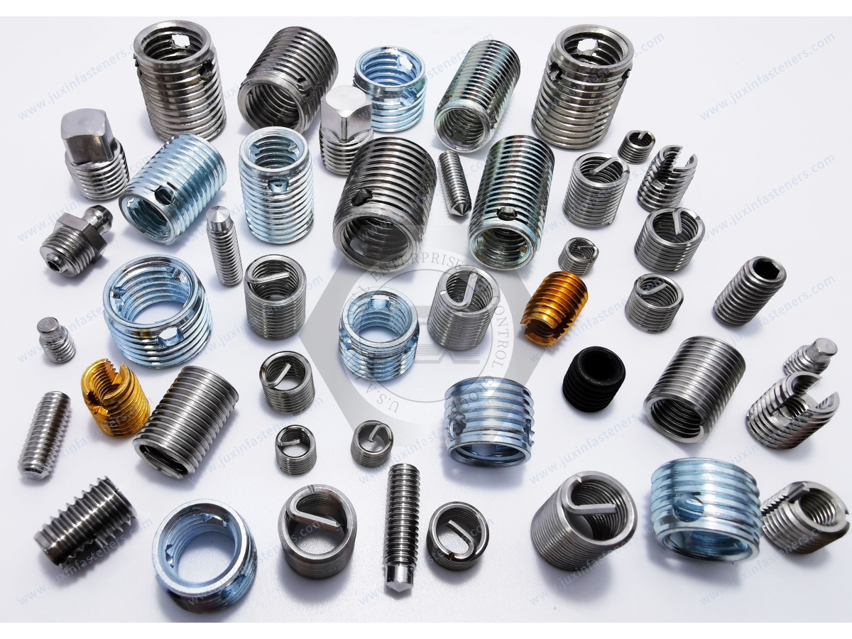
Juxin Fasteners supplies industrial set screws and drawing-specific fastening components.
Relevant product categories include:
18-8 stainless steel cup point set screws
A2 stainless steel cup point set screws
A4 stainless steel cup point set screws
Carbon steel cup point set screws
DIN 916 / ISO 4029 cup point set screws
Custom hex socket set screws
Material grades, dimensions, compliance, inspection requirements, MOQ and lead times are subject to confirmation.
Request a Quote for Stainless Steel Cup Point Set Screws
Are you sourcing stainless steel cup point set screws for shafts, pulleys, collars, industrial machinery or a drawing-specific OEM project?
Juxin Fasteners welcomes inquiries from mechanical engineers, design engineers, production managers, manufacturing engineers, purchasing specialists and supplier development teams.
For technical review and quotation, please provide:
Screw drawing and revision + DIN 916 / ISO 4029 or other applicable specification + thread diameter and pitch + length
+ cup point geometry + hex socket dimensions + material grade + mechanical requirements + surface finish + mating shaft material and hardness
+ installation torque requirements + inspection documentation + prototype quantity + annual demand + packaging + target delivery schedule.
Company: Juxin Fasteners
Website: https://www.juxinfasteners.com/
Email: info@juxinfasteners.com
Send your stainless steel cup point set screw drawings and OEM RFQ to Juxin Fasteners for technical confirmation, product selection and quotation.
Contact Us
Tel.:
+86 020 8621 0320
+86 020 3121 6067
E-mail:
Technical Support:
Navigation
SEND INQUIREY



