
Call Us
+86 136 6007 9809
Call Us
+86 136 6007 9809

Aug. 16, 2023
Telecommunications equipment places very different demands on fasteners depending on where the joint is located.
An outdoor antenna mounting structure, a weather-exposed communication cabinet, an RF equipment housing, a thin sheet-metal chassis,
an optical networking enclosure, and an internal service panel may all belong to the same telecommunications system, but they should not automatically use the same fastening strategy.
For design engineers, the challenge is to match the fastener to the mechanical function, parent material, installation process, environmental exposure, service requirements,
and any application-specific electrical or magnetic considerations.
For procurement and supplier-development teams, the challenge is different: converting those engineering requirements into a sourcing specification that can be quoted,
manufactured, inspected, documented, and supplied consistently.
JUXIN FASTENERS supplies telecommunications equipment fasteners and custom mechanical components for B2B OEM and industrial applications,
including self-clinching nuts, self-clinching studs, stainless steel screws and nuts, high-strength fasteners, brass hardware, blind rivet nuts, plastic fastening components, and drawing-based custom parts.
This guide connects engineering selection with commercial sourcing so that telecommunications fasteners are specified according to the actual joint rather than a generic product name.

A telecommunications system can contain several mechanical layers:
Support Structure → Mounting Bracket → Equipment Enclosure → Sheet-Metal Chassis → Electronic Module → Internal Fixture
Each interface performs a different function.
A structural mounting joint may need to transfer significant external loads.
A sheet-metal enclosure may need a permanent internal thread.
An access cover may require repeated removal during field maintenance.
An RF-sensitive assembly may have specific material or magnetic-property requirements.
An outdoor cabinet may require corrosion management across several dissimilar materials.
This creates an important engineering rule:
Select the fastener by joint function and installation environment—not simply by the fact that the equipment belongs to the telecommunications industry.
That distinction prevents both over-specification and under-specification.
One useful way to specify telecommunications equipment fasteners is to divide the assembly into functional zones.
Typical applications can include:
Antenna mounting structures
Equipment support frames
Rooftop mounting systems
Outdoor structural brackets
Equipment mounting frames
Heavy external assemblies
Engineering priorities may include:
Joint loading
Clamp load
Fastener strength
Vibration
Fatigue considerations
Corrosion exposure
Installation method
Inspection requirements
Structural fasteners should be selected according to the actual load path and applicable equipment or structural specification.
A fastener suitable for an enclosure panel should not automatically be substituted into a structural mounting joint.
Typical applications can include:
Communication cabinets
Electronic enclosures
Equipment chassis
Internal mounting plates
Access panels
Cooling assemblies
Cable-management brackets
Power supply housings
Engineering priorities can include:
Sheet thickness
Parent material
Hole geometry
Thread retention
Push-out resistance
Torque-out resistance
Installation access
Repeated assembly
Self-clinching fasteners are particularly relevant in this zone.
Potential applications can include:
RF equipment housings
Filter housings
Shielding structures
Microwave-related equipment
Instrumentation
Selected antenna electronics
Depending on the equipment design, engineers may need to consider:
Material
Magnetic properties
Residual magnetism
Electrical contact
Surface condition
Corrosion
Mechanical stability
EMC-related interfaces
Not every telecommunications fastener requires special magnetic properties.
Such requirements should be defined only where the equipment design actually needs them.
Typical applications can include:
Optical networking equipment
Rack-mounted equipment
Control modules
Internal brackets
PCB support structures
Cable-routing systems
Replaceable modules
Service panels
Engineering priorities can include:
Compact dimensions
Accessibility
Repeated assembly
Thread durability
Component retention
Ease of maintenance
This zone-based approach helps engineers avoid specifying one “premium” fastener for every location regardless of actual function.
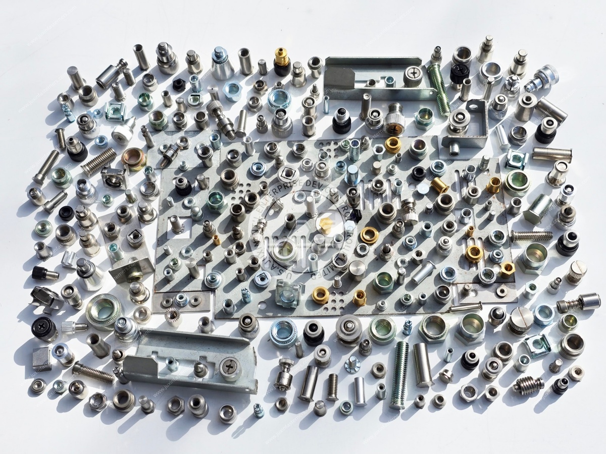
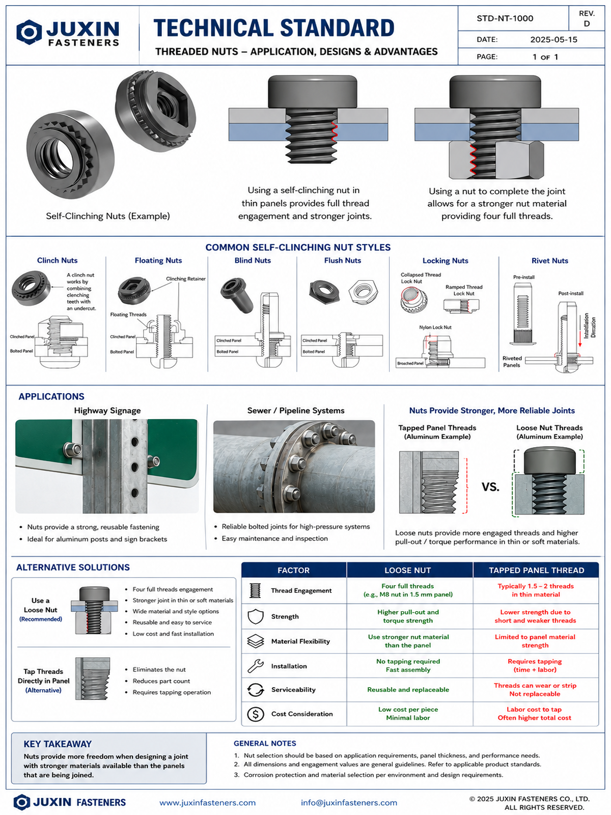
Self-clinching nuts are one of the most useful fastening technologies for telecommunications sheet-metal assemblies.
A self-clinching nut is installed into a correctly prepared hole using controlled pressing force.
During installation, the parent sheet is displaced into the fastener's designed retention feature, creating mechanical retention within the panel.
The result is a permanently retained internal thread.
Potential telecommunications applications include:
Equipment chassis
Communication cabinets
Electronic enclosures
Internal brackets
Cable-management assemblies
Cooling-system brackets
Mounting plates
Access panels
Serviceable sheet-metal structures
For OEM production, this can reduce dependence on loose nuts during final assembly while creating a repeatable threaded attachment point.
However, self-clinching nuts are not simply “pressed into any thin sheet.”
Their performance depends on the relationship between:
Fastener Geometry + Hole + Sheet Material + Sheet Thickness + Installation Process
A common sourcing mistake is to specify a self-clinching nut by thread size while treating the mounting hole as a secondary manufacturing detail.
The mounting hole is actually part of the fastening system.
A hole that is too large may reduce the intended retention.
A hole that is too small may prevent correct installation or cause unwanted panel deformation.
Hole condition can also matter.
Engineering teams should consider:
Hole diameter
Hole tolerance
Hole roundness
Burr condition
Sheet material
Sheet thickness
Edge distance
Fastener geometry
Installation direction
Installation tooling
For production programs, the fastener and panel should therefore be evaluated together.
When evaluating self-clinching nuts, two performance terms are frequently encountered:
Push-Out Resistance
and
Torque-Out Resistance
They describe different failure modes.
Push-out resistance relates to axial loading that tends to remove the installed fastener from the sheet.
Torque-out resistance relates to rotational loading that tends to rotate the installed fastener within the sheet.
A self-clinching nut may behave differently under these two loading conditions.
Therefore, an engineering drawing or OEM specification should identify the performance requirement relevant to the actual joint instead of using a general statement such as “high-strength clinch nut.”
Where functional testing is required, the test method and acceptance criteria should be defined by the customer specification or applicable product requirement.
Self-clinching technology depends on controlled interaction between the fastener and parent material.
The engineer should evaluate:
Sheet material
Sheet thickness
Material hardness
Material ductility
Hole geometry
Fastener retention geometry
Installation force
Required mechanical performance
Potential telecommunications enclosure materials include:
Carbon steel sheet
Stainless steel sheet
Aluminum sheet
Coated sheet materials
The suitability of a particular self-clinching fastener should be confirmed for the actual substrate rather than assumed from another application.
This becomes especially important when an enclosure design changes material or thickness during cost reduction or lightweighting.
A fastener validated in one panel should not automatically be assumed to provide identical retention in a different panel.
Telecommunications equipment manufacturers have several options for creating threaded attachment points.
The correct choice depends on the assembly.
| Engineering Requirement | Self-Clinching Nut | Weld Nut | Blind Rivet Nut | Loose Nut |
|---|---|---|---|---|
| Thin sheet-metal thread | Strong candidate where substrate is suitable | Possible where welding is suitable | Strong candidate | Possible |
| Permanent captive thread | Yes | Yes | Yes | No |
| One-sided installation after enclosure forming | Usually not the primary advantage | Usually limited | Strong advantage | Usually difficult |
| Avoid localized welding | Yes | No | Yes | Yes |
| Press installation | Required | No | No | No |
| Suitable for closed/inaccessible rear structures | Depends on manufacturing sequence | Depends on process | Often useful | Usually difficult |
| Repeated screw installation | Can be suitable | Can be suitable | Can be suitable | Can be suitable |
| Retrofit or late-stage installation | Usually limited | Usually limited | Often useful | Depends on access |
The objective is not to identify a universally superior fastening technology.
The objective is to select the joining method that fits the equipment architecture, manufacturing sequence, panel material, installation access, service requirements, and production volume.
Telecommunications assemblies do not require internal threads only.
Some equipment requires a permanently retained external thread or a controlled spacing function.
Self-clinching studs may be considered for:
Internal mounting brackets
Equipment modules
Grounding-related mechanical interfaces where specifically designed
Cable-management structures
Electronic enclosure assemblies
Fixed mounting locations
Self-clinching standoffs may support:
PCB mounting
Electronic modules
Control boards
Internal spacing
Shielding assemblies
Equipment chassis
Thread, length, standoff height, sheet material, panel thickness, installation method, and loading should be specified according to the actual assembly.
Stainless steel fasteners can be considered where corrosion resistance, appearance, material compatibility, or environmental durability is important.
Potential applications include:
Outdoor communication cabinets
Antenna equipment
Equipment enclosures
Coastal installations
Industrial communication equipment
Humid environments
Serviceable external hardware
Common stainless fastener families may include A2 and A4 materials, with specific grades such as 304 or 316 identified where appropriate to the customer's specification.
Applicable stainless fastener standards can include relevant parts of ISO 3506 within their respective product and property-class scopes.
However:
“Stainless steel” is not a complete environmental specification.
Material selection should consider:
Outdoor exposure
Humidity
Chlorides
Industrial contamination
Temperature
Mating material
Required mechanical properties
Surface condition
Maintenance requirements
Selecting stainless steel does not automatically eliminate corrosion risk.

A common telecommunications assembly may combine:
Aluminum Enclosure + Stainless Steel Fastener + Coated Steel Bracket
Each material may be individually corrosion resistant, yet the combination can create additional concerns when electrically connected in the presence of moisture or another electrolyte.
Galvanic-corrosion risk can depend on:
Material combination
Electrical contact
Relative exposed areas
Moisture
Chloride exposure
Surface treatment
Protective coatings
Joint geometry
Drainage
Crevice conditions
This leads to another important design principle:
Corrosion protection is a system decision, not simply a fastener-material decision.
Changing a fastener from coated carbon steel to stainless steel can alter the galvanic relationship with an aluminum enclosure.
Adding a washer, coating, isolation layer, or different surface treatment can also change the interface.
The complete material system should therefore be evaluated.
Steel telecommunications fasteners may use different corrosion-protection systems depending on the application and customer specification.
Potential systems can include:
Zinc-based coatings
Zinc-nickel coatings
Zinc-flake coatings
Application-specific topcoats
Customer-specified coating systems
Relevant international standards can include ISO 4042 for electroplated coating systems on fasteners and ISO 10683 for non-electrolytically applied zinc-flake coating systems within their applicable scopes.
ASTM specifications may also apply where required by the customer drawing or purchasing specification.
The correct specification should define the coating system and required validation rather than relying on a vague phrase such as “outdoor coating.”
Salt-spray testing is often used when comparing or qualifying corrosion-protection systems.
ASTM B117 provides a controlled salt-spray test environment.
But:
Salt-Spray Hours ≠ Guaranteed Outdoor Service Life
A telecommunications installation can experience combinations of:
Rain
Condensation
Chlorides
UV exposure
Thermal cycling
Industrial pollution
Mechanical damage
Crevice conditions
Water retention
Laboratory salt-spray exposure does not reproduce all these conditions.
Therefore, purchasing teams should not select a coating solely because one supplier states a larger salt-spray-hour number.
A stronger specification defines:
Coating System + Test Method + Exposure Requirement + Acceptance Criteria + Application Environment
This makes supplier quotations easier to compare and reduces ambiguous corrosion claims.
Telecommunications equipment can experience vibration from several sources:
Wind
Fans
Cooling systems
Mechanical equipment
Transportation
Structural movement
The engineering question is not simply whether a fastener is “vibration resistant.”
Engineers should first determine:
What is the load path?
Is the joint primarily structural or enclosure-level?
Is preload important?
Is the joint repeatedly serviced?
Can joint movement occur?
Is the fastener exposed to cyclic shear or tension?
Is an anti-loosening feature required?
Potential concerns include:
Thread loosening
Joint slip
Fretting
Wear
Fatigue
Loss of clamp load
The correct locking strategy depends on the joint.
Locking nuts, prevailing-torque fasteners, thread-locking systems, washer systems, or other retention methods may be considered where appropriate, but they should not replace correct joint design.
Outdoor telecommunications equipment can experience repeated temperature changes.
An assembly such as:
Aluminum Enclosure + Stainless Steel Fastener + Steel Internal Bracket
contains materials with different coefficients of thermal expansion.
Temperature cycling can influence:
Clamp load
Contact pressure
Joint movement
Sealing interfaces
Component alignment
Electrical contact interfaces
Where thermal movement is significant, engineers should evaluate the complete assembly rather than the fastener alone.
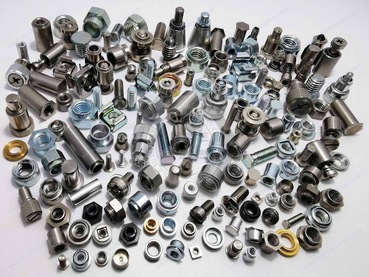
Some RF, instrumentation, electronic, and measurement applications may define requirements for magnetic behavior.
However, not every telecommunications fastener needs to be non-magnetic.
Over-specifying magnetic requirements can increase cost and restrict material options without providing a functional benefit.
A better engineering sequence is:
Identify Sensitive Location → Define Magnetic Requirement → Select Material → Define Verification
The terms:
Non-magnetic
Low magnetic permeability
Low residual magnetism
should not automatically be treated as equivalent.
For example, some austenitic stainless steels can have relatively low magnetic permeability compared with ferromagnetic steels, but manufacturing and cold working may influence magnetic response.
Where magnetic properties are critical, the customer specification should define:
Material grade
Required magnetic characteristic
Test method
Acceptance criterion
Critical installation location
This converts a vague purchasing request into a measurable engineering requirement.
Fasteners can participate in the mechanical and electrical architecture of telecommunications equipment.
They may contribute to:
Panel attachment
Mechanical bonding
Chassis connections
Contact pressure
Shielding interfaces
But a fastener alone does not guarantee EMC or RF performance.
System behavior can depend on:
Enclosure geometry
Panel interfaces
Grounding architecture
Conductive contact surfaces
Gaskets
Cable entry points
Seams
Fastener spacing
Surface treatments
Therefore, RF and EMC requirements should be evaluated at the equipment level.
The fastener should then be specified according to the function it performs within that system.
Some telecommunications and electronic equipment uses brass or other copper-alloy mechanical components.
Potential applications can include:
Electrical hardware
Terminal-related mechanical components
Instrumentation
Compact threaded components
Electronic assemblies
Customer-specific conductive mechanical parts
Material selection should balance:
Mechanical + Electrical + Corrosion + Thermal + Manufacturing Requirements
Electrical conductivity alone is not sufficient reason to select a material.
A brass component, for example, may offer useful electrical characteristics but different mechanical behavior from stainless or alloy steel.
Similarly, phosphor bronze or another copper alloy may be selected where spring characteristics or electrical functions are important.
The customer drawing should define the actual alloy where material properties are critical.
Communication cabinets and electronic equipment often contain numerous serviceable components.
Potential fastening products include:
Self-clinching nuts
Self-clinching studs
Self-clinching standoffs
Stainless steel screws
Machine screws
Locking nuts
Washers
Blind rivet nuts
Captive hardware
Plastic fasteners
Custom CNC machined components
The preferred solution depends on whether the joint is:
Structural
Serviceable
Adjustable
Permanently installed
Electrically functional
Environmentally exposed
This distinction helps prevent the common sourcing mistake of selecting fasteners by product family before defining the joint function.
A telecommunications enclosure may be opened multiple times during its operating life.
That changes the fastener-selection problem.
Engineering teams should ask:
Will the thread be reused?
How many service cycles are expected?
Can repeated torque affect the parent sheet?
Will the captive fastener remain securely retained?
Is tool access sufficient?
Can corrosion affect future disassembly?
Is the mating screw material compatible?
Could the thread be damaged during field maintenance?
A fastening solution optimized only for initial factory assembly may not be the best solution for equipment requiring repeated field service.
This service-cycle perspective can provide more useful engineering value than simply minimizing initial component cost.
Standard fasteners are often the preferred starting point because they can simplify sourcing and reduce unnecessary customization.
Custom parts become relevant when the application requires characteristics that available standard components do not provide.
Custom requirements may include:
Non-standard length
Special head geometry
Special thread
Reduced profile
Application-specific retention geometry
Special material
Customer-specific coating
Controlled magnetic properties
Drawing-controlled dimensions
Special packaging
Integrated mechanical functions
Before creating a custom part, engineering teams should determine whether the requirement comes from a genuine functional constraint or simply from historical design practice.
Where a custom component is justified, the drawing should define the critical characteristics rather than relying on a product description alone.
| Application | Common Fastening Options | Key Engineering Questions |
|---|---|---|
| Outdoor structural mounting | Bolts, nuts, locking fasteners | Load, preload, vibration, corrosion, environment |
| Sheet-metal enclosure | Self-clinching nuts, studs, rivet nuts | Sheet material, thickness, hole, retention |
| Closed enclosure with one-side access | Blind rivet nuts | Hole, grip range, anti-rotation, service requirement |
| Electronic chassis | Self-clinching fasteners, screws, standoffs | Space, sheet thickness, repeated assembly |
| RF-sensitive equipment | Application-specific stainless, brass or specialty hardware | Magnetic properties, contact, EMC interface |
| Outdoor cabinet | Stainless or coated fasteners | Corrosion system, galvanic compatibility, maintenance |
| PCB or internal module | Standoffs, small screws, plastic hardware | Spacing, insulation, compact geometry |
| Service panel | Captive or permanently retained threaded systems | Repeated removal, access, thread durability |
This matrix should be used as a screening tool rather than a substitute for application-specific engineering.
For a new telecommunications equipment program, engineering should ideally define:
Structural
Enclosure
Mounting
Serviceable
Electrical interface
RF-sensitive
Alignment
Spacing
Thread
Size
Load direction
Clamp-load requirement where applicable
Vibration
Retention requirement
Push-out or torque-out where relevant
Expected service cycles
Carbon steel
Stainless steel
Aluminum
Plastic
Composite or other specified material
Indoor or outdoor
Humidity
Salt exposure
Industrial contamination
Temperature
Thermal cycling
Chemical exposure
Magnetic-property control
Electrical contact
Isolation
Corrosion protection
Surface treatment
Repeated maintenance
Customer-specific testing
Defining these factors before selecting the part number reduces downstream sourcing changes.
Procurement often receives a fastener request only after a product design is substantially complete.
A vague request such as:
“Need stainless telecom screws.”
is difficult to quote accurately.
A stronger sourcing package includes:
Engineering drawing
Drawing revision
Fastener type
Thread size and pitch
Critical dimensions
Material
Surface treatment
Parent material
Sheet thickness where applicable
Mating component
Environmental requirement
Magnetic requirement where applicable
Mechanical or functional tests
Inspection requirements
Documentation requirements
Prototype quantity
Annual volume
Packaging requirements
This allows suppliers to quote the same technical requirement rather than making different assumptions.
A design engineer searching for telecommunications equipment fasteners may be trying to answer questions such as:
Which fastener works in thin sheet metal?
Should I use a self-clinching nut or rivet nut?
What hole condition does a clinch nut require?
How do I avoid galvanic corrosion with an aluminum enclosure?
Do I actually need a non-magnetic fastener?
Which fastening method works for repeated service access?
How should vibration influence the joint design?
A purchasing manager or supplier-development engineer may search for:
Telecommunications fastener manufacturer
Telecom equipment fastener supplier
Self-clinching nut supplier
Custom telecom screws manufacturer
Stainless steel telecom fastener supplier
OEM communication equipment fasteners
Drawing-based fastener manufacturer
A useful B2B technical page should answer both search journeys.
Engineering determines what should be specified.
Procurement determines who can manufacture and supply it consistently.
For OEM telecommunications programs, supplier qualification may include several dimensions.
Evaluate whether the supplier can:
Interpret engineering drawings
Understand parent-material requirements
Review thread and tolerance requirements
Evaluate sheet-metal fastening conditions
Support standard and custom parts
Communicate technical questions before production
Depending on the product, relevant processes can include:
Cold forming
Thread forming or rolling
Machining
Self-clinching fastener production
Custom screw manufacturing
Surface-treatment coordination
Custom mechanical-component manufacturing
Potential requirements can include:
Incoming material control
Dimensional inspection
Thread inspection
Surface-condition inspection
Functional testing where specified
Inspection records
Traceability
Change control
Procurement teams may also evaluate:
Production capacity
Prototype support
Repeat-order capability
Lead-time planning
Packaging
Export documentation
Supply continuity
Engineering communication
The exact qualification process should follow the customer's supplier-quality requirements and component risk.
Depending on the customer, product, destination market, and application, procurement may request:
Certificate of Conformance
Material documentation
Inspection reports
Coating documentation
RoHS information
REACH information
Restricted-substance declarations
Customer-specific quality records
Compliance should be evaluated against the actual product, material, finish, and applicable customer requirement.
A generic statement that every fastener is “compliant” is less useful than product-specific documentation tied to the actual supplied part.
A practical telecommunications fastener sourcing path is:
Equipment Architecture
→ Fastening Zone
→ Joint Function
→ Parent Material
→ Mechanical Requirement
→ Fastener Technology
→ Thread and Geometry
→ Material
→ Corrosion / Magnetic / Environmental Requirements
→ Installation Process
→ Validation
→ Inspection and Documentation
→ Supplier Qualification
→ Prototype
→ Production RFQ
This is the commercial conversion path that connects engineering search intent with purchasing action.
Instead of asking a supplier only:
“What is your price for this fastener?”
the buyer can ask:
“Can you manufacture and validate this fastener against our drawing, parent material, installation process, environment, documentation requirements, and annual volume?”
That is a much stronger B2B sourcing question.
For quotation and engineering review, provide as much of the following information as available:
2D drawing and 3D model where available
Part number and drawing revision
Fastener type
Thread specification
Critical dimensions and tolerances
Material
Surface treatment
Parent material
Sheet thickness for sheet-metal fasteners
Mounting-hole requirement where applicable
Mating component or mating screw
Application environment
Corrosion requirement
Magnetic-property requirement where applicable
Functional testing requirement
Inspection and documentation requirements
Prototype quantity
Annual production volume
Packaging requirement
Delivery destination or applicable logistics requirement
For self-clinching nuts, always include the parent sheet material and thickness.
For outdoor equipment, define the corrosion environment rather than requesting a generic “corrosion-resistant fastener.”
For magnetically sensitive equipment, define the actual magnetic-property requirement and verification method.
For custom components, provide the controlled engineering drawing.
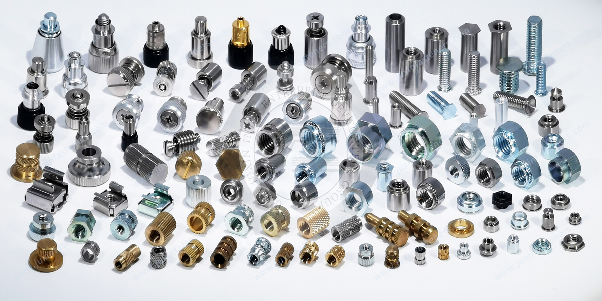
JUXIN FASTENERS supports B2B OEM customers with fastening and custom mechanical components for telecommunications and electronic equipment.
Relevant product categories include:
Self-clinching nuts
Self-clinching studs
Self-clinching standoffs
Blind rivet nuts
Blind rivets
Stainless steel screws and nuts
High-strength bolts and nuts
Locking fasteners
Brass threaded components
Plastic and nylon fasteners
Threaded inserts
Custom screws
CNC machined components
Drawing-based special fasteners
Product selection can be based on:
Customer drawings
Internationally recognized standards where applicable
Material requirements
Parent material
Installation process
Environmental exposure
Mechanical requirements
Inspection requirements
Documentation requirements
Production quantity
The objective is not simply to sell a catalog fastener.
The objective is to identify a fastening configuration that fits the actual telecommunications equipment architecture and can be manufactured, inspected, documented, and supplied consistently.
Telecommunications equipment programs may progress through:
Concept → Mechanical Design → Prototype → Engineering Validation → Pilot Production → Production → Repeat Supply
Fastener requirements can change during this process.
A prototype may use a conventional nut and screw because it is readily available.
During production engineering, the same assembly may move to a self-clinching nut, captive fastener, rivet nut, or custom component to improve assembly access or manufacturing efficiency.
A drawing-based sourcing process helps control these changes.
Before production release, engineering and procurement should confirm:
Final drawing revision
Material
Surface treatment
Installation condition
Functional requirements
Inspection plan
Documentation
Packaging
Production quantity
Change-control requirements
This creates a clearer transition from prototype sourcing to repeat OEM supply.
If you are developing telecommunications equipment, RF hardware, communication cabinets, outdoor enclosures, antenna systems, optical networking equipment,
electronic chassis, or other industrial communication systems, JUXIN FASTENERS can evaluate your fastening requirements from both engineering and sourcing perspectives.
Send your drawing, CAD file, sample, or available technical specification.
For the most useful evaluation, include:
Fastener type
Thread
Dimensions
Material
Surface treatment
Parent material
Sheet thickness
Application
Environmental conditions
Corrosion requirements
Magnetic-property requirements where applicable
Functional testing requirements
Prototype quantity
Annual volume
Inspection requirements
Documentation requirements
Packaging requirements
For OEM, purchasing, supplier-development, engineering, and supply-chain inquiries:
Email: info@juxinfasteners.com
JUXIN FASTENERS supports telecommunications equipment manufacturers with standard and custom fastening solutions from engineering specification and sample development through production sourcing and repeat supply.
 MORE NEWS

Sep. 25, 2026

Sep. 25, 2026

Sep. 25, 2026
Contact Us
Tel.:
+86 020 8621 0320
+86 020 3121 6067
E-mail:
Technical Support:
Navigation
SEND INQUIREY