
Call Us
+86 136 6007 9809
Call Us
+86 136 6007 9809

Mar. 30, 2026
Threaded Inserts for Industrial Electrical Panels: Control Cabinet Design and OEM Assembly
Industrial electrical control panels are becoming more compact, modular and functionally complex.
Modern control cabinets and electrical equipment may incorporate programmable logic controllers (PLCs), relays,
circuit protection devices, communication modules, metering equipment and monitoring systems.
These components require reliable mounting arrangements that support equipment operation, maintenance access and repeatable production assembly.
Industrial electrical panels and their supporting components may be manufactured from:
Engineering plastics
Reinforced polymer materials
Thin-gauge steel
Aluminum sheet
Composite materials
These materials have different mechanical properties and fastening requirements.
Directly formed threads in some plastics may wear after repeated screw installation.
Thin sheet metal may provide insufficient engagement for a conventional machine screw. Dynamic equipment loading and temperature changes can also affect joint behavior.
Threaded inserts for industrial electrical panels provide reusable internal metal threads when selected for a suitable host material and installation process.
However, a threaded insert is only one component of the fastening system.
Electrical equipment designers must also consider joint loading, material thickness, installation access, insulation, protective bonding and maintenance requirements.
Manufacturing engineers and production managers must evaluate installation repeatability, assembly time, tooling and defect prevention.
Purchasing and supplier development teams must consider drawing compliance, material specifications, inspection requirements, annual demand and long-term sourcing conditions.
Juxin Fasteners welcomes OEM inquiries for threaded inserts and custom fastening components used in industrial electrical equipment.
Why Industrial Electrical Panels Need Reliable Threaded Connections
Industrial electrical systems may require inspection, troubleshooting, component replacement and periodic maintenance.
Typical serviceable assemblies include:
PLC mounting structures
Relay support components
Electronic module housings
Metering equipment
Instrument panels
Control cabinet accessories
Protective covers
Repeated maintenance can place additional demands on threaded connections.
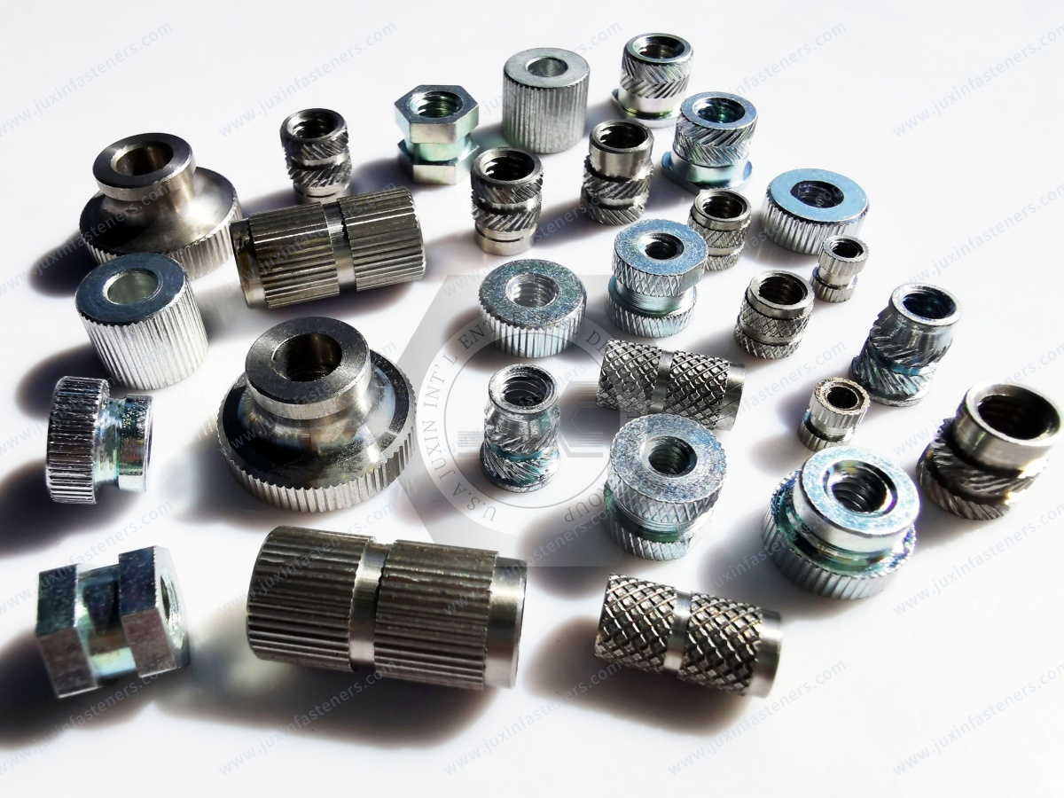
Common Fastening Challenges
Thread Wear
Repeated screw installation may damage directly formed threads in certain plastics.
Material Creep
Some polymers gradually deform under sustained loading, potentially reducing joint compression.
Vibration
Mechanical vibration may contribute to relative movement or loosening when the joint is inadequately designed.
Thin Material Sections
Thin sheet metal may not provide sufficient thread engagement for a directly tapped hole.
Maintenance Damage
Incorrect screw installation or excessive tightening can damage the host component.
Potential Benefits of Threaded Inserts
Reusable internal metal threads
Reduced wear during repeated assembly
More consistent mating thread geometry
Greater flexibility in machine screw selection
Improved serviceability in suitable designs
Compatibility with controlled production assembly
Important Engineering Clarification
Threaded inserts do not automatically prevent screw loosening, eliminate plastic creep or guarantee higher pull-out resistance.
Actual performance depends on insert geometry, host material, installation quality and joint design.
Electrical Panel Fastening: Host Material Comes First
The first selection decision should be based on the actual component material.
Engineering Plastic Components
Suitable options may include:
Self-tapping threaded inserts designed for compatible plastics
Molded-in threaded inserts
Press-in threaded inserts
Heat-set inserts for suitable thermoplastics
The surrounding plastic geometry strongly influences retention.
Thin Steel and Aluminum Panels
Depending on sheet thickness, hardness and installation access, suitable alternatives may include:
Self-clinching threaded nuts
Blind rivet nuts
Weld nuts
Other sheet-metal-specific threaded fastening systems
Important Distinction
Plastic threaded inserts and sheet-metal captive fasteners are not interchangeable.
They use different installation and retention mechanisms.
Engineering Recommendation
Confirm the host material, thickness, access conditions, load direction and service requirements before specifying the fastening system.
Mechanical Retention and Joint Integrity
Electrical panel components require secure positioning throughout the intended service life.
The fastening system must be evaluated for the actual component mass, operating environment and maintenance requirements.
Pull-Out Resistance
Pull-out resistance describes the ability of an installed insert to resist axial extraction from the host material.
Torque-Out Resistance
Torque-out resistance describes the ability of an installed insert to resist rotation within the host material.
Screw Thread Strength
The internal thread must withstand the intended screw tightening and service loads.
Host Material Strength
The surrounding plastic or metal must withstand insertion and joint loading.
Engineering Recommendation
Treat these as separate performance characteristics.
An insert may resist pull-out but rotate during tightening.
Alternatively, an insert may resist rotation while the surrounding material fails under axial loading.
Reusable Fastening for Electrical Equipment Maintenance
Industrial electrical equipment often requires access for:
Component replacement
Wiring inspection
Instrument servicing
PLC module upgrades
Relay replacement
Troubleshooting
A suitable threaded insert can reduce wear associated with repeated screw installation in a plastic component.
However, serviceability depends on the complete assembly.
Important Considerations
Insert retention
Mating screw condition
Thread alignment
Tightening torque
Access for tools
Expected service cycles
Engineering Recommendation
If repeated maintenance is expected, define the required assembly-cycle performance and validate the connection.
Vibration and Screw Loosening
Industrial automation systems may experience vibration from nearby machinery, motors or mechanical equipment.
Potential causes of screw loosening include:
Inadequate preload
Transverse vibration
Joint settlement
Material creep
Thermal expansion
Insufficient joint stiffness
Important Clarification
A threaded insert does not inherently prevent the mating screw from loosening.
Where required, a suitable locking method or another validated joint design may be necessary.
Engineering Recommendation
Evaluate insert retention and screw loosening separately.
Brass Threaded Inserts for Electrical Panel Plastics
Brass is commonly used for threaded inserts in suitable engineering plastic components.
Potential Advantages
Good machinability
Durable internal metal threads
Compatibility with many established plastic insertion designs
Useful corrosion resistance in appropriate environments
Electrical conductivity where relevant to the design
Potential Applications
Plastic control housings
Electronic module supports
Instrument enclosures
PLC accessory housings
Selected electrical panel components
Engineering Considerations
Host polymer grade
Boss dimensions
Installation process
Thermal expansion
Pull-out resistance
Torque-out resistance
Important Clarification
Brass does not prevent creep in the surrounding plastic.
A brass insert also does not automatically establish a reliable electrical grounding connection.
Stainless Steel Threaded Inserts
Stainless steel may be considered where particular mechanical or corrosion properties are required.
Potential Applications
Outdoor electrical equipment
Humid industrial facilities
Selected automation equipment
Specialized instrumentation
Engineering Considerations
Stainless steel grade
Corrosion exposure
Mating screw material
Thread galling
Installation compatibility
Cost
Stainless steel corrosion resistance depends on the selected grade and operating environment.
Aluminum Threaded Inserts
Aluminum inserts may be considered for selected lightweight electrical equipment designs.
Potential Advantages
Lower density
Compatibility with certain lightweight design concepts
Potential reduction in component mass
Engineering Considerations
Aluminum alloy
Internal thread wear
Surface treatment
Galvanic corrosion
Installation method
Repeated assembly requirements
Aluminum inserts are not automatically the most economical or strongest option.
Material Selection Comparison
| Material | Potential advantage | Main design consideration |
|---|---|---|
| Brass | Machinability and established plastic insert designs | Host material and retention |
| Stainless steel | Grade-dependent corrosion and mechanical properties | Corrosion, galling and cost |
| Aluminum | Lower density | Thread durability and galvanic effects |
Engineering Recommendation
Specify the actual material grade and finish on the approved drawing.
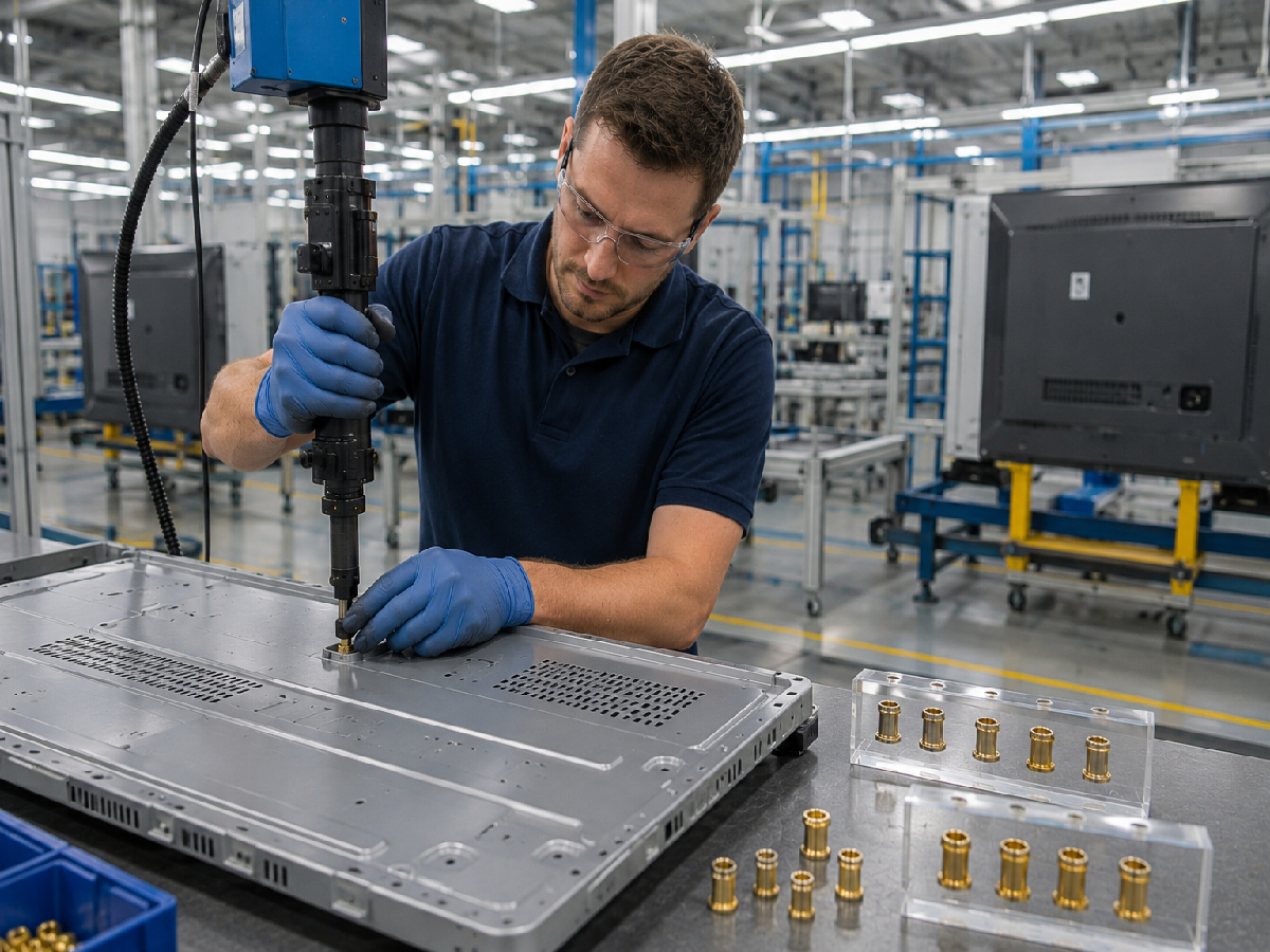
Self-Tapping Threaded Inserts
Self-tapping threaded inserts contain premanufactured internal machine threads.
During installation, their external cutting or forming features establish engagement with a compatible host material.
Potential Advantages
Post-production installation
Mechanical retention in suitable materials
No separate heating step for compatible designs
Flexible use in selected assembly processes
Engineering Limitations
Pilot hole dimensions are critical
Installation torque must be controlled
Brittle plastics may crack
Thin walls may deform
Misalignment may damage the component
Potential Applications
Suitable plastic control housings
Selected equipment mounting components
Industrial instrument assemblies
Important Clarification
Self-tapping inserts do not normally create their own internal threads during installation.
Molded-In Threaded Inserts
Molded-in inserts are positioned inside the mold before injection molding.
Plastic flows around the insert and its retention features during the molding process.
Potential Advantages
Integrated insert placement
No separate post-molding insertion operation
Suitability for selected high-volume production
Potential for effective mechanical retention
Engineering Limitations
Insert positioning must be controlled
Mold loading can affect cycle time
Plastic flow requires evaluation
Insert displacement may create defects
Tooling complexity may increase
Important Clarification
Molded-in inserts do not automatically provide maximum retention strength.
Performance depends on insert geometry, host material and molding conditions.
Press-In Threaded Inserts
Press-in inserts are installed into appropriately prepared holes using controlled mechanical force.
Their retention features engage the surrounding material.
Potential Advantages
Relatively straightforward installation
No heating requirement
Potential for efficient production
Suitability for selected applications
Engineering Limitations
Host material compatibility is critical
Hole diameter affects retention
Excessive insertion force may damage the component
Pull-out and torque-out performance require validation
Important Distinction
Press-in inserts for plastics should not be confused with self-clinching nuts for sheet metal.
Heat-Set Inserts for Plastic Control Components
For suitable thermoplastics, heat-set inserts provide another installation option.
Controlled heating softens the surrounding plastic and allows retention features to become embedded.
Potential Advantages
Post-molding installation
Reusable metal threads
Compatibility with many engineering thermoplastics
Established insertion processes
Engineering Limitations
Installation temperature must be controlled
Pilot hole geometry affects retention
Excessive heat may damage the component
Incomplete insertion may affect screw engagement
Installation Method Comparison
| Method | Typical host material | Key process variable |
|---|---|---|
| Self-tapping | Compatible plastic or other specified substrate | Installation torque and hole size |
| Molded-in | Injection-molded plastic | Insert positioning and molding conditions |
| Press-in | Compatible host material | Insertion force and hole geometry |
| Heat-set | Suitable thermoplastic | Temperature and seating depth |
The appropriate method depends on the actual enclosure component and production process.
Plastic Boss Design and Installation Geometry
The surrounding plastic boss is an important part of the threaded insert connection.
Pilot Hole Diameter
An oversized hole may reduce insert retention.
An undersized hole may cause excessive insertion stress.
Boss Outside Diameter
The boss must provide sufficient surrounding material.
Boss Height
Boss height influences insert engagement and available screw depth.
Hole Depth
Blind holes must provide adequate clearance for the insert and mating screw.
Edge Distance
Inserts placed close to unsupported edges may create stress concentrations.
Engineering Recommendation
Before tooling release, confirm:
Insert outside diameter
Insert length
Pilot hole diameter
Hole depth
Boss outside diameter
Boss height
Edge distance
Mating screw engagement
Clearance beneath the screw
Installation Process Control
For manufacturing engineers and production managers, installation consistency is essential.
Depending on the insert type, relevant variables include:
Hole dimensions
Installation torque
Insertion force
Insertion temperature
Alignment
Seating depth
Tool condition
Host material condition
Production Quality Indicators
Installation cycle time
Seating depth variation
Reject rate
Rework rate
Tool wear
Dimensional consistency
Retention test results
Information Gain: Production Variation Can Control Installed Retention
An insert may achieve satisfactory retention during prototype testing but perform inconsistently in production if the installation process varies.
For example, variation in pilot hole diameter or insert alignment can affect retention even when the inserts themselves meet dimensional specifications.
Engineering Recommendation
Validate the intended production process, not only the insert drawing.
Electrical Safety: Mechanical Fastening vs Electrical Function
Industrial electrical panels involve electrical requirements beyond mechanical retention.
A threaded insert may provide a mounting connection, but it does not independently establish electrical safety.
Electrical Insulation
A metal insert is conductive.
Where installed in a plastic component, its location must be evaluated relative to electrical clearance and insulation requirements.
Protective Bonding
Some conductive equipment parts require an appropriate protective bonding connection.
A metal insert embedded in plastic does not automatically provide a reliable protective earth path.
Electrical Connections
Threaded inserts intended for mechanical mounting should not automatically be used as current-carrying electrical terminals.
Relevant Equipment Requirements
Depending on the application, IEC 60204-1 may be relevant to electrical equipment of machinery.
IEC 61439 may be relevant to certain low-voltage switchgear and controlgear assemblies.
The applicable requirements must be determined for the complete equipment design.
Engineering Recommendation
Evaluate mechanical fastening, electrical insulation and protective bonding as separate design functions.
Temperature Changes and Material Creep
Industrial electrical equipment may experience temperature changes caused by operating conditions and the surrounding environment.
Metals and polymers generally have different thermal expansion characteristics.
Potential effects include:
Local stress changes
Insert movement
Boss cracking
Joint relaxation
Changes in screw preload
Plastic Creep
Some polymers gradually deform under sustained loading.
This can reduce joint compression over time.
Engineering Recommendation
Evaluate the complete connection under representative temperature and loading conditions.
Control Cabinet and PLC Mounting Applications
Threaded inserts may support selected mounting structures for:
PLC accessory housings
Relay mounting components
Electronic module supports
Control system covers
Instrument mounting structures
Engineering Priorities
Component positioning
Maintenance access
Thread durability
Assembly consistency
Electrical clearance
Important Application Distinction
Many PLCs, relays and electrical devices are mounted using DIN rails or other dedicated mounting systems.
Threaded inserts are not a universal replacement for these systems.
Their use should be limited to compatible mounting components and approved equipment designs.
Distribution Boards and Switchgear Assemblies
Selected insulating housings, covers and auxiliary components may use threaded inserts.
Engineering Priorities
Mechanical retention
Electrical insulation
Thermal behavior
Maintenance access
Applicable equipment requirements
Important Limitation
Safety-critical or current-carrying connections require dedicated validation.
Metering and Monitoring Equipment
Potential applications include:
Instrument housings
Measurement modules
Monitoring system covers
Serviceable electronic enclosures
Engineering Priorities
Precise positioning
Repeated servicing
Dimensional stability
Corrosion resistance
Industrial Automation Cabinets
Potential applications include:
Controller housings
Equipment covers
Communication modules
Auxiliary mounting components
Engineering Priorities
Assembly repeatability
Vibration-related joint design
Maintenance efficiency
Long-term component availability
Common Failure Modes and Engineering Prevention
| Failure mode | Potential cause | Recommended evaluation |
|---|---|---|
| Insert pulls out | Insufficient retention or weak host material | Review geometry and axial loading |
| Insert rotates | Inadequate anti-rotation engagement | Review retention features and torque-out |
| Plastic boss cracks | Excessive insertion stress | Review hole and boss design |
| Internal thread strips | Incorrect screw or excessive torque | Review thread fit and tightening |
| Joint loses preload | Plastic creep or settlement | Evaluate joint relaxation |
| Screw loosens | Vibration or inadequate preload | Review complete joint design |
| Insert corrodes | Unsuitable material or environment | Review material and finish |
| Electrical clearance is inadequate | Incorrect conductive component placement | Review insulation design |
| Protective bonding is inadequate | Unverified conductive path | Validate bonding arrangement |
| Production defects increase | Installation variation | Improve process control |
Quality Control for Industrial Electrical Panel Threaded Inserts
Quality requirements should reflect the actual joint function.
Incoming Product Inspection
Potential characteristics include:
Material grade
Internal thread dimensions
Outside diameter
Insert length
Retention geometry
Surface finish
Visual defects
Installed Insert Inspection
Potential checks include:
Position
Seating depth
Perpendicularity
Host material damage
Insert movement
Thread condition
Mechanical Validation
Depending on the application:
Pull-out testing
Torque-out testing
Repeated assembly testing
Screw tightening trials
Joint load testing
Environmental Validation
Where relevant:
Thermal cycling
Temperature aging
Humidity exposure
Corrosion evaluation
Vibration testing
Important Qualification Principle
A correctly manufactured threaded insert is not automatically suitable for every electrical panel application.
The installed joint and complete equipment design must meet the relevant requirements.
Thread Standards and Dimensional Compatibility
The insert's internal thread must match the mating screw.
Metric Threads
ISO 261 and the ISO 965 series may be relevant to applicable metric thread dimensions and tolerances.
Unified Inch Threads
ASME B1.1 covers Unified inch screw threads, including UNC and UNF designations.
Metric-to-Inch Diameter References
| Metric size | Approximate nominal diameter |
|---|---|
| M3 | 0.118 in |
| M4 | 0.157 in |
| M5 | 0.197 in |
| M6 | 0.236 in |
| M8 | 0.315 in |
These values are dimensional conversions only.
Metric, UNC, UNF, BSW and BSF threads are not directly interchangeable.
Specific thread availability must be confirmed against the drawing.
Total Installed Cost for Electrical Panel OEM Production
The lowest insert purchase price does not always produce the lowest assembly cost.
Relevant cost elements include:
Insert purchase price
Installation labor
Tooling
Equipment depreciation
Inspection
Scrap and rework
Maintenance
Replacement components
Information Gain: Compare Cost per Accepted Assembly
A useful production comparison is:
Total relevant production and installation costs ÷ accepted assembly quantity
Use a consistent production period and avoid double-counting costs.
Engineering Recommendation
Compare fastening alternatives using production volume, cycle time, defect rate and maintenance requirements.
Custom Threaded Inserts for Industrial Electrical Equipment
Some OEM applications require drawing-specific threaded inserts.
Potential custom requirements include:
Internal thread size
Thread pitch
Insert length
Outside diameter
Retention geometry
Material grade
Surface finish
Installation method
Packaging requirements
Engineering Recommendation
Provide the complete insert drawing and host component information.
The host material and installation process are important for evaluating actual performance.
Supplier Qualification and Bulk Procurement
Purchasing and supplier development teams should evaluate technical and commercial factors together.
Technical Evaluation
Drawing compliance
Material specification
Thread accuracy
Retention geometry
Surface finish
Inspection requirements
Manufacturing Evaluation
Dimensional consistency
Installation compatibility
Process control
Traceability where required
Engineering change management
Commercial Evaluation
Prototype requirements
MOQ
Annual demand
Unit price
Lead time
Production planning
Supply continuity
Specific commercial conditions require confirmation for each RFQ.
OEM RFQ Checklist
| RFQ item | Information to provide |
|---|---|
| Product drawing | Part number and revision |
| Insert type | Self-tapping, molded-in, press-in, heat-set or specified |
| Thread | Metric or inch designation |
| Insert dimensions | OD, length and tolerances |
| Material | Brass, stainless steel, aluminum or specified |
| Host material | Plastic grade, metal or composite |
| Host geometry | Boss or sheet thickness and hole dimensions |
| Installation | Method and equipment |
| Loading | Axial, torsional and service loads |
| Vibration | Operating conditions |
| Temperature | Operating range |
| Electrical requirements | Insulation or bonding considerations |
| Maintenance | Expected assembly cycles |
| Testing | Pull-out, torque-out or specified tests |
| Samples | Prototype quantity |
| Annual demand | Volume forecast |
| MOQ | Commercial confirmation |
| Lead time | Required schedule |
| Packaging | Bulk or production-compatible |
Frequently Asked Questions
What are threaded inserts used for in industrial electrical panels?
They provide reusable internal metal threads in selected plastic and lightweight components used in control cabinets, instrument housings and automation equipment.
Can threaded inserts be used to mount PLCs and relays?
They may support suitable mounting structures or housings, but many PLCs and relays use DIN rails or dedicated mounting systems.
Are brass threaded inserts suitable for electrical panel plastics?
They may be suitable for compatible engineering thermoplastics, subject to retention, temperature and electrical design requirements.
Do threaded inserts prevent screw loosening?
Not inherently. Screw loosening and insert retention must be evaluated separately.
Can threaded inserts provide protective grounding?
Not automatically. The complete conductive path must be designed and verified.
Which insert type provides the highest pull-out strength?
No installation method is universally strongest.
Performance depends on insert geometry, host material and installation conditions.
Can threaded inserts be used in thin steel panels?
Thin sheet metal often requires a dedicated fastening system such as a self-clinching nut or blind rivet nut.
Can electrical panel inserts use UNC or UNF threads?
Such requirements can be reviewed against the drawing.
Availability must be confirmed, and Unified inch threads are not interchangeable with metric threads.
What information is needed for a bulk OEM quotation?
Provide the drawing, material, thread specification, host material, installation method, expected volume and delivery schedule.
Juxin Fasteners: Industrial Electrical Panel Threaded Insert Solutions
Juxin Fasteners welcomes inquiries for industrial threaded inserts and custom fastening components.
Relevant product categories include:
Brass threaded inserts
Stainless steel threaded inserts
Aluminum threaded inserts
Self-tapping threaded inserts
Molded-in threaded inserts
Press-in threaded inserts
Heat-set threaded inserts
Custom threaded inserts
Drawing-specific industrial fastening components
Specific dimensions, material grades, installation requirements, inspection criteria, MOQ and delivery schedules require confirmation.
Request an Industrial Electrical Panel Threaded Insert Quotation
Are you developing a control cabinet, PLC accessory housing, relay support, metering enclosure,
distribution board or industrial automation assembly requiring reusable threaded connections?
Juxin Fasteners welcomes inquiries from:
Electrical equipment design engineers
Mechanical engineers
Structural engineers
Manufacturing engineers
Production managers
Purchasing specialists
Procurement managers
Supplier development teams
Supply chain managers
For technical review, please provide:
Insert drawing + thread specification + material grade + host material + boss or sheet thickness + hole dimensions
+ installation method + load requirements + vibration conditions + operating environment + electrical requirements
+ inspection criteria + prototype quantity + annual demand + packaging + delivery schedule.
Our team can review the requirements and confirm suitable product options, technical feasibility and quotation conditions.
Company: Juxin Fasteners
Website: https://www.juxinfasteners.com/
Email: info@juxinfasteners.com
Send your industrial electrical panel threaded insert drawings and OEM RFQ to Juxin Fasteners for technical confirmation and quotation.
Contact Us
Tel.:
+86 020 8621 0320
+86 020 3121 6067
E-mail:
Technical Support:
Navigation
SEND INQUIREY



