
Call Us
+86 136 6007 9809
Call Us
+86 136 6007 9809

Nov. 19, 2024
Weld Stud and Weld Nut Design Guide: Hole Geometry, Projection Welding and OEM Assembly Validation
Weld studs and weld nuts provide permanent threaded attachment points in automotive sheet metal structures, electric vehicle battery enclosures, industrial equipment and fabricated metal assemblies.
They allow subsequent components to be installed with bolts or nuts without requiring access to both sides of every joint.
However, a welded threaded attachment is only as reliable as the complete connection between the fastener and its parent material.
A weld nut may have a correctly manufactured internal thread but fail because of inadequate weld formation.
A weld stud may satisfy dimensional requirements yet create assembly problems because of angular misalignment or poor positioning.
In automated production, small variations in sheet thickness, hole location, electrode condition or component presentation can affect both weld quality and downstream assembly efficiency.
For these reasons, weld stud design and weld nut design must integrate fastener geometry, welding process, parent material,
installation tolerances and functional testing.
Juxin Fasteners supplies weld studs, weld nuts and drawing-specific industrial fastening components for OEM applications.
This guide focuses on the engineering decisions that should be resolved before tooling approval, pilot production and serial manufacturing.
Weld Studs and Weld Nuts: Understanding the Product and Process Differences
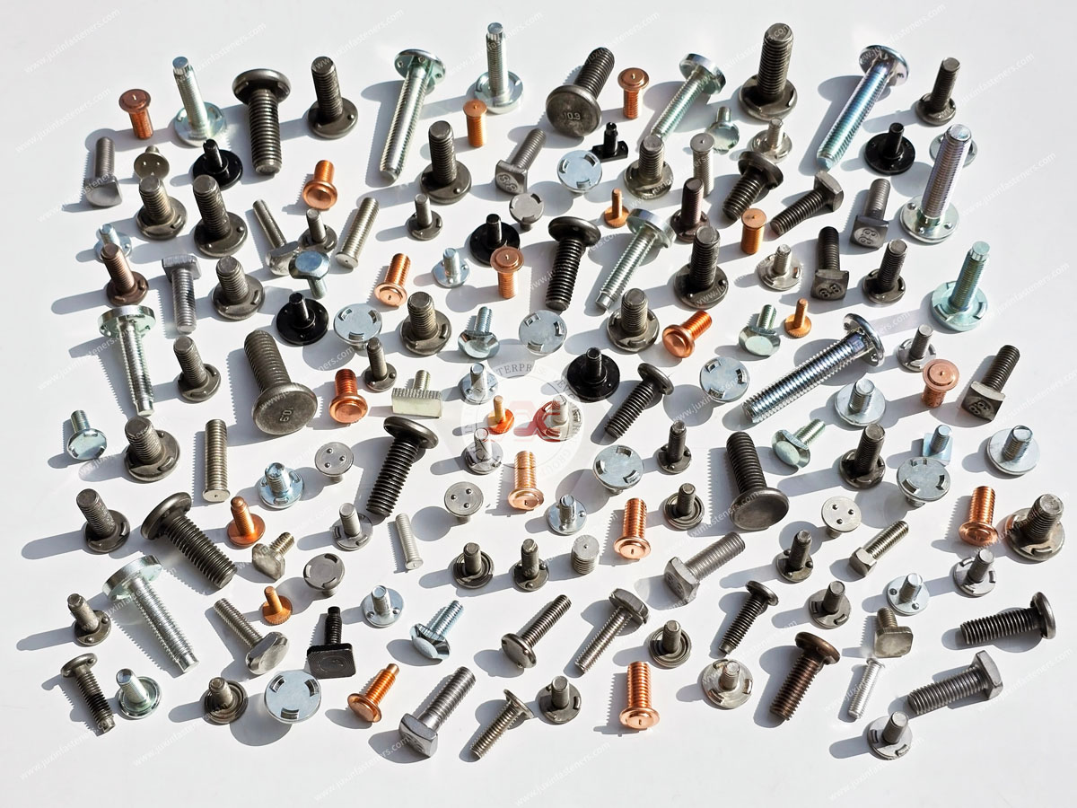
A weld stud is a fastener with an externally threaded section or other functional mounting geometry that is attached to a metal component through welding.
A weld nut is an internally threaded component intended to be welded to a parent material to create a fixed threaded attachment.
Although both are welded fasteners, their welding methods are not necessarily the same.
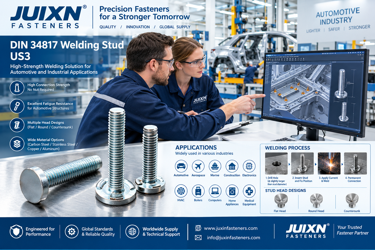
Projection Weld Studs
Projection weld studs incorporate geometry suitable for resistance projection welding.
The projection or contact features concentrate current and force at intended weld locations.
Capacitor Discharge Weld Studs
Capacitor discharge (CD) studs are designed for a short-duration stud welding process.
Their tip geometry and process requirements differ from those of resistance projection weld studs.
Drawn Arc Weld Studs
Drawn arc stud welding uses an arc welding process and may be selected for appropriate stud sizes, base materials and structural requirements.
Projection Weld Nuts
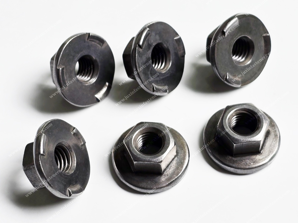
Projection weld nuts typically incorporate welding projections or designed contact features on the face intended to contact the sheet metal.
The fastener geometry, welding equipment and acceptance criteria must match the selected process.
A CD weld stud, a drawn arc weld stud and a projection weld stud should not be treated as interchangeable simply because their nominal thread size is identical.
Weld Nut Geometry and Product Selection
Weld nuts are available in different configurations to suit access, sheet metal design, welding method and assembly requirements.
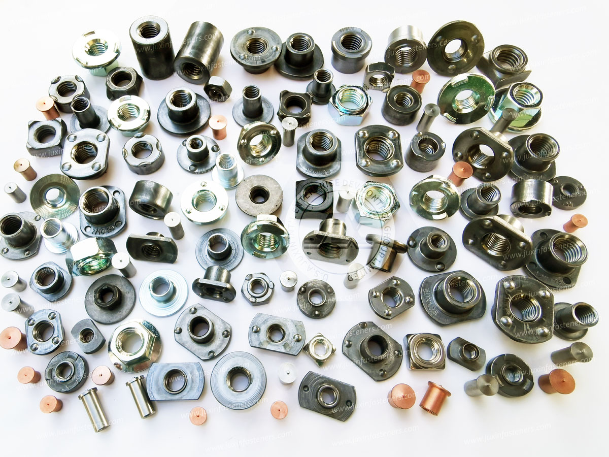
Common designs include hex weld nuts, square weld nuts, flange weld nuts and drawing-specific automotive weld nuts.
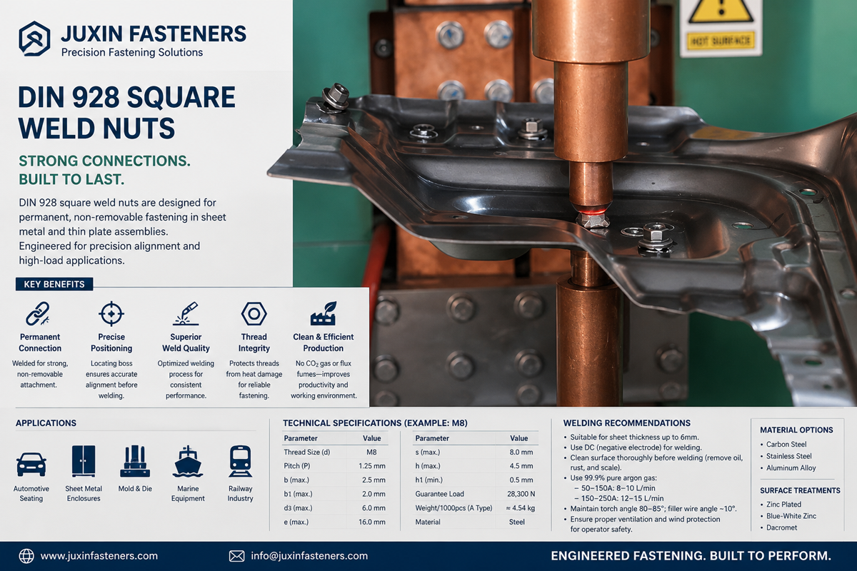
DIN 928 Square Weld Nuts
DIN 928 provides a recognized dimensional reference for square weld nuts.
Their geometry may suit selected sheet metal welding arrangements where positioning and welding access are appropriate.
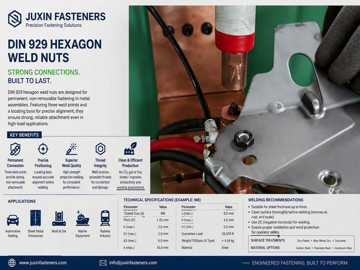
DIN 929 Hex Weld Nuts
DIN 929 is a recognized reference for hexagon weld nuts.
The specified product dimensions and welding features must be checked against the relevant drawing and application.
ISO 21670 Weld Nuts
ISO 21670 covers specified hexagon weld nut designs.
The applicable product type, dimensions and technical requirements should be confirmed against the standard and customer drawing.
Special Automotive Weld Nuts
Drawing-specific weld nuts may incorporate locating pilots, flanges, restricted-height profiles, special projections or features intended for automated handling.
A safety-related or high-load application may require additional customer-defined performance requirements beyond a general dimensional standard.
Selection Principle
Choose the weld nut design according to the available sheet thickness, locating method, welding process, electrode access and downstream bolt assembly—not solely by thread diameter.
Automotive Body-in-White Weld Fastener Design
Automotive body-in-white (BIW) structures commonly contain welded threaded attachment points for brackets, interior components, equipment supports and other assemblies.
Welded fasteners can be incorporated into automated sheet metal manufacturing sequences, allowing mounting points to be prepared before subsequent assembly operations.
The engineering challenge is to maintain accurate fastener positioning and weld integrity despite variations in sheet metal stamping, fixture location, part handling and welding equipment.
Design Factors for BIW Assemblies
Sheet material and thickness
Hole position relative to stamped features
Fastener locating geometry
Access for welding electrodes or stud welding equipment
Distortion and dimensional changes during manufacturing
Corrosion protection after welding
Bolt installation direction and access
Functional loads transferred through the welded attachment
A weld nut installed in a difficult-to-access area may be inexpensive as an individual component but expensive to repair after vehicle body assembly.
For production managers, prevention of missing nuts, mislocated fasteners and incomplete welds is therefore an important part of overall manufacturing cost control.
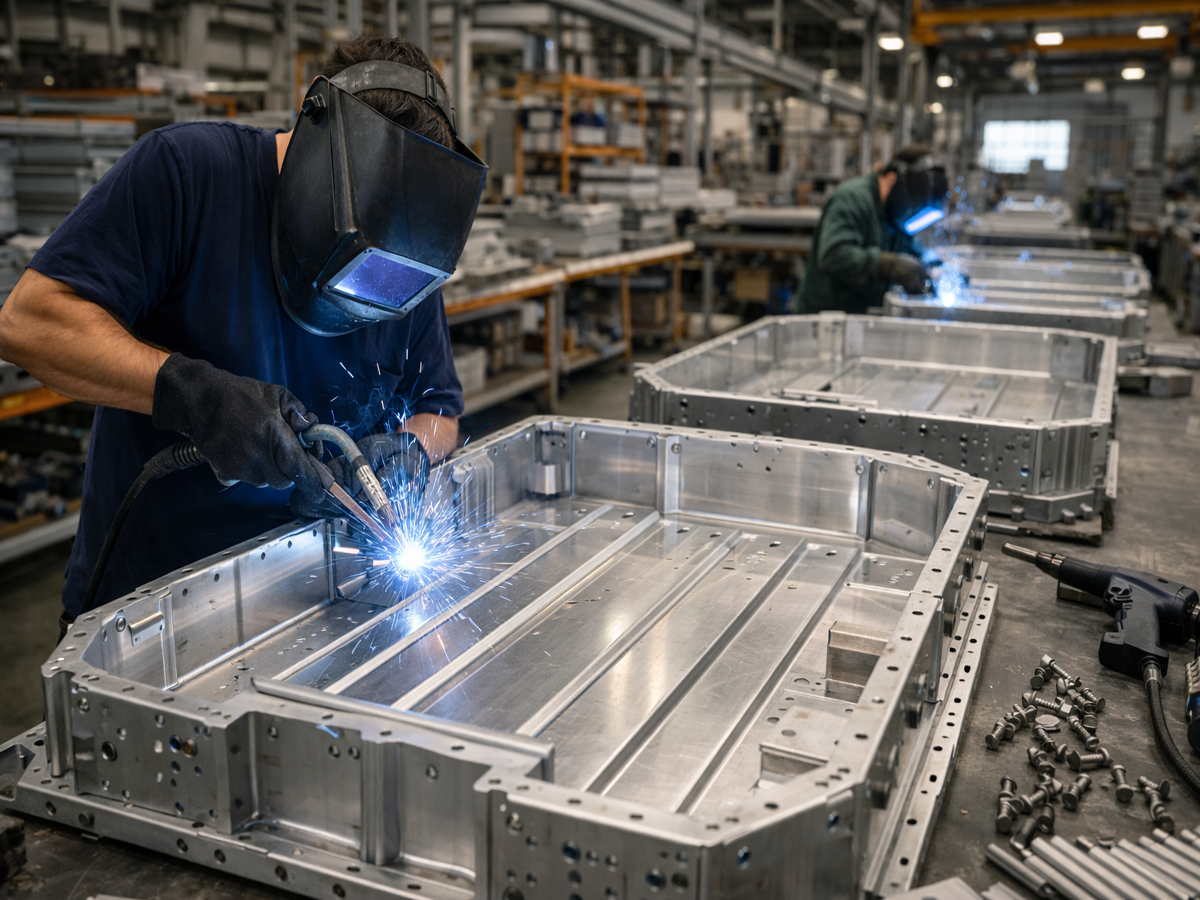
Weld Stud Product Design and Relevant Standards
Different stud welding processes require different stud-end geometries, welding equipment and material combinations.
For suitable stud welding applications, ISO 13918 addresses studs and ceramic ferrules for arc stud welding, while ISO 14555 provides requirements for arc stud welding of metallic materials.
These references are relevant to applicable arc stud welding processes; they should not be presented as universal specifications for all resistance projection welded fasteners.
Other product references, including DIN 34817 or applicable IFI 148 configurations, may be relevant where the specific fastener type and drawing correspond to their scope.
Before specifying a standard, confirm the actual stud geometry, material, welding method and required product designation.
Stud Length and Assembly Clearance
A welded stud must provide sufficient usable thread engagement after accounting for mating component thickness, washer arrangement and installation requirements.
The designer should also check interference between the stud base, weld features and adjacent sheet metal geometry.
Stud Perpendicularity
Angular misalignment can make bolt or nut installation difficult, particularly where the mating component has a close-fitting hole or limited assembly clearance.
Perpendicularity requirements should be established from the actual joint geometry and downstream assembly process.
Weld Stud Material Selection
Carbon steel, stainless steel and selected aluminum stud designs may be considered where compatible with the intended welding process and parent material.
Material compatibility must be evaluated rather than assuming that every stud material can be welded successfully to every sheet metal grade.
Weld Nut Product Standards and Custom Geometry
Standardized weld nuts can simplify sourcing when their geometry satisfies the assembly requirements.
However, automotive and industrial OEM applications sometimes require a custom weld nut because of restricted space, specific locating features or a particular welding process.
For example, a conventional hex weld nut may not fit a narrow stamped channel, while a special low-profile or offset configuration may provide the required installation access.
Any change in nut geometry can also change weld projection placement, electrode contact conditions and resistance to applied loads.
Engineering Recommendation
When considering a custom weld nut, evaluate the full weld and assembly process before finalizing the fastener drawing.
Sheet Metal Hole Design: Diameter, Location and Thickness
Hole geometry is one of the most important interfaces between the weld fastener and the parent sheet.
A locating hole may help position a weld nut, but the appropriate hole diameter depends on the nut's pilot or locating feature, required clearance, stamping tolerances and welding arrangement.
A hole that is too small may prevent correct seating or damage the locating feature. A hole that is too large may permit excessive positional variation or reduce local support.
Not every weld nut requires the same locating-hole arrangement. Some designs use a pilot; others depend on tooling or other locating features.
Key Drawing Inputs
| Design feature | Engineering consideration | Potential problem if uncontrolled |
|---|---|---|
| Sheet thickness | Parent material stiffness and weldability | Distortion, inadequate support or inconsistent weld formation |
| Locating-hole diameter | Fit with nut pilot or locating feature | Interference or excessive movement |
| Hole position | Alignment with downstream assembly | Bolt insertion difficulty |
| Edge distance | Available sheet material and local load path | Deformation or local failure |
| Fastener orientation | Installation access and welding presentation | Misassembly or tooling interference |
| Weld projection geometry | Current concentration and weld formation | Incomplete or inconsistent weld |
| Thread engagement | Mating bolt and joint requirements | Thread stripping or inadequate connection |
There is no single universal hole diameter or sheet thickness suitable for every weld nut design.
The correct values must come from the applicable product standard, approved drawing and validated welding process.
Multi-Layer Sheet Metal Considerations
Welding through multiple sheet layers introduces additional electrical, thermal and dimensional interfaces.
Such arrangements require specific process development and validation. A weld nut qualified on a single sheet should not automatically be approved for a multilayer assembly.
Projection Design and Resistance Welding Performance
In resistance projection welding, welding projections concentrate electrical current and mechanical force at defined contact points.
As the projections heat and collapse, the process must form suitable welded connections between the fastener and parent material.
Weld quality depends on more than the nominal current setting.
Important factors include electrode force, current profile, weld time, projection geometry, material condition, sheet thickness, equipment setup and electrode wear.
Why Projection Geometry Matters
If projections differ in height or contact condition, current and force may not be distributed as intended.
This can produce uneven weld formation, incomplete attachment or local expulsion.
A nut may appear seated against the sheet but still have insufficient weld strength.
Engineering Recommendation
Projection geometry should be treated as a functional feature.
Its dimensions and tolerances should be controlled according to the approved product design and welding process.
Electrode Access and Tooling
The welding process must allow suitable electrode contact and force application without interfering with nearby formed features.
Restricted access can affect tooling selection, cycle time and weld consistency.
For high-volume production, designers should involve manufacturing engineers before finalizing surrounding sheet metal geometry.
Thread Accuracy and Protection During Welding
The threaded portion of a weld stud or weld nut must remain functional after welding.
For applicable metric threads, ISO 724 defines basic dimensions and ISO 965 addresses tolerance requirements.
External and internal thread tolerance classes, such as 6g and 6H where specified, should be selected according to the product standard and customer drawing.
A weld nut's thread may be affected by weld spatter, heat, deformation or coating buildup.
The required inspection method should therefore consider the condition of the finished welded assembly, not only the fastener before welding.
Why Thread Alignment Matters
A weld nut that is offset relative to the panel hole may cause a mating bolt to contact the sheet edge or enter the thread at an angle.
This can create false tightening torque, cross-threading or damage during automated assembly.
The acceptable offset depends on the bolt diameter, panel hole, assembly clearance, tool alignment and joint design.
A universal positional tolerance should not be assigned without the applicable drawing requirements.
Surface Treatment: Welding Before or After Coating?
Surface protection is essential in many automotive and industrial environments, but coatings can influence welding behavior.
The correct coating sequence depends on the fastener material, parent material, welding method and finished assembly requirements.
Welding on Uncoated or Prepared Surfaces
Some welding arrangements require clean or specifically prepared contact surfaces to achieve consistent weld formation.
Welding on Coated Sheet Metal
Where coated sheet is used, the coating can influence electrical contact, heat generation, electrode condition and weld quality.
The welding process must be developed for the actual sheet material and coating system.
Coating After Welding
Post-weld finishing may provide corrosion protection to the assembled structure, but coverage around the weld interface and threaded areas requires attention.
Pre-Coated Fasteners
A pre-coated weld nut or stud should not be assumed weldable without process validation.
Certain coatings can interfere with electrical contact or weld formation.
Common Coating Options
Zinc plating, zinc-nickel and zinc-flake systems may be relevant to suitable fasteners or finished assemblies.
Their applicability depends on the welding sequence, material and corrosion requirements.
For high-strength steel fasteners, hydrogen embrittlement risks associated with certain processing routes must also be assessed where applicable.
Engineering Recommendation
Define the welding and corrosion-protection sequence together.
Do not select a coating based only on salt-spray performance while ignoring its influence on weldability.
Mechanical Properties Versus Welded Joint Strength
The mechanical properties of the fastener and the strength of its welded attachment are separate engineering considerations.
For applicable carbon and alloy steel externally threaded fasteners, ISO 898-1 provides mechanical property requirements within its scope.
For applicable internally threaded nuts, ISO 898-2 provides relevant mechanical property requirements within its scope.
However, these standards do not establish the complete strength of a particular weld between the fastener and sheet metal.
A nut may meet its material or thread strength requirements while its weld attachment fails at a lower applied load.
Engineering Recommendation
Specify both the fastener's mechanical requirements and the welded attachment's functional acceptance criteria.
Weld Nut Torque-Out Testing
Torque-out testing evaluates resistance to rotation or failure of the installed welded nut under a defined test procedure.
The result depends on the nut design, weld geometry, parent material and testing configuration.
The acceptance value should be established from the relevant drawing or customer specification.
Weld Stud Torque Resistance
Where a welded stud is subjected to torque during assembly, its attachment may require an appropriate torsional resistance test.
This is different from measuring the tightening torque–clamp force relationship of a conventional bolted joint.
Push-Out and Pull-Off Testing
Push-out or pull-off tests may be used to evaluate resistance to axial separation, depending on the welded fastener geometry and loading direction.
The test setup must represent the intended failure mode and applicable customer requirement.
Destructive Versus Non-Destructive Verification
Destructive testing may be used during process development, sample approval or defined production checks to investigate weld strength and failure behavior.
Non-destructive checks may be useful for selected process controls, but they should not be assumed to establish the same information as a destructive strength test.
Engineering Recommendation
Agree on the test method, loading direction, fixture, acceptance criteria, sample frequency and required failure observations before production release.
Common Weld Fastener Failure Modes
| Failure mode | Possible contributing factors | Engineering response |
|---|---|---|
| Weld nut rotates during tightening | Inadequate weld attachment or excessive assembly load | Review weld quality and torque-out requirements |
| Weld stud separates from sheet | Inadequate fusion or unsuitable loading | Review process and attachment strength |
| Bolt cannot enter weld nut | Hole misalignment or thread damage | Review positioning and thread protection |
| Uneven weld formation | Projection or electrode variation | Review projection geometry and welding setup |
| Parent sheet tears around attachment | Local material or geometry limitations | Review sheet thickness and load path |
| Thread strips before required assembly load | Insufficient thread capacity or unsuitable mating bolt | Review thread engagement and material requirements |
| Corrosion develops near weld | Inadequate finished protection | Review coating sequence and coverage |
Failure analysis should examine both the fastener and the parent material. Replacing the nut with a higher-strength grade will not necessarily solve a problem caused by insufficient weld formation.
Automotive and EV Applications
Body-in-White Structures
Weld nuts and weld studs may be used for body brackets, interior attachment points, equipment mounts and other suitable threaded connections.
The main engineering priorities include accurate positioning, reliable weld formation and compatibility with subsequent manufacturing operations.
EV Battery Enclosures
Battery enclosures may require threaded attachments for covers, brackets and auxiliary equipment.
The weld fastener must be evaluated together with enclosure material, sealing requirements, thermal conditions and service loads.
For thin or lightweight structures, excessive installation torque can damage the parent material even when the weld fastener itself remains intact.
Electrical Cabinets and Power Equipment
Weld nuts and studs can provide permanent attachment points for panels, brackets and equipment supports.
Designers should consider access, corrosion protection, electrical requirements and maintenance procedures.
Industrial Machinery and Transportation Equipment
Welded fasteners may be appropriate for machine guards, equipment frames and fabricated assemblies where a permanent threaded attachment is advantageous.
Highly loaded or safety-critical applications require the applicable engineering validation and customer approval.
Production-Line Design: Preventing Assembly Problems Before They Occur
Manufacturing engineers and production managers must consider how weld fasteners will be presented, located, welded, inspected and assembled.
A technically suitable weld nut can still create production problems if its geometry is difficult to orient in an automatic feeder or if the surrounding sheet metal prevents reliable electrode access.
Production Planning Considerations
Part orientation and feeding consistency
Missing-fastener detection
Correct nut or stud selection
Welding equipment accessibility
Electrode maintenance
Thread protection
Dimensional verification
Weld strength sampling
Rework and repair procedures
Traceability and process change control
The required controls depend on the production process and the criticality of the application.
Pilot Production and Process Validation
Before serial production, a pilot build can help identify whether the approved fastener design performs consistently with actual stamped parts and production equipment.
A practical review should examine dimensional fit, weld formation, thread usability, functional strength and downstream assembly access.
Where customer requirements call for process capability studies, production part approval documentation or specific inspection records, these should be defined in the project scope.
Engineering Recommendation
A weld fastener should be qualified as part of the actual manufacturing system, not only as an isolated component.
Supplier Development and OEM Purchasing Requirements
Purchasing and supplier development teams should evaluate weld fasteners according to their functional requirements rather than nominal thread size and unit price alone.
A lower-priced weld nut may increase total installed cost if it requires additional inspection, causes welding downtime or creates downstream assembly failures.
Supplier qualification should consider product geometry, material consistency, welding compatibility, dimensional control, documentation and change management.
OEM Weld Fastener RFQ Checklist
| RFQ information | Why it matters |
|---|---|
| Part drawing and revision | Establishes the approved geometry |
| Product standard, if applicable | Identifies dimensional requirements |
| Thread size and tolerance | Defines mating fastener compatibility |
| Material specification | Supports mechanical and weldability review |
| Parent sheet material and thickness | Defines the welding interface |
| Hole and locating geometry | Supports installation and positioning |
| Welding process | Determines suitable fastener design |
| Surface treatment and process sequence | Supports weldability and corrosion planning |
| Functional strength requirements | Establishes torque-out or axial test needs |
| Dimensional and positional tolerances | Supports assembly reliability |
| Inspection and documentation requirements | Supports supplier approval |
| Annual demand, MOQ and delivery schedule | Supports commercial planning |
Supplier Substitution Risk
Two weld nuts with the same thread size may differ in projection geometry, locating pilot dimensions or welding behavior.
Therefore, a replacement part should not be approved solely because it fits the same bolt.
Where the weld interface changes, the customer may need to repeat relevant welding and assembly validation.
Frequently Asked Questions
What is the difference between a weld stud and a weld nut?
A weld stud provides an externally threaded or other projecting attachment, while a weld nut provides an internally threaded attachment.
Are all weld studs installed by projection welding?
No. Studs may be designed for resistance projection welding, capacitor discharge welding or drawn arc stud welding, depending on their geometry and application.
Which standards apply to weld nuts?
DIN 928, DIN 929 and ISO 21670 may be relevant to particular weld nut designs. The applicable standard must match the product configuration.
How do I select the hole diameter for a weld nut?
Use the approved fastener drawing, locating geometry, parent sheet requirements and validated welding arrangement. There is no universal hole size for every weld nut.
Does ISO 898-2 guarantee weld nut attachment strength?
No. The nut's mechanical properties and the welded joint's strength are separate requirements.
What tests are used for weld nut attachment strength?
Depending on the application, torque-out, push-out, pull-off or other customer-defined tests may be specified.
Can zinc-plated weld nuts be welded directly?
Suitability depends on the coating, material and welding process. Pre-coated fasteners require specific weldability validation.
Can Juxin Fasteners supply custom weld studs and weld nuts?
Juxin Fasteners welcomes drawing-specific inquiries. The applicable geometry, material, coating, testing and production requirements must be confirmed.
Juxin Fasteners: OEM Weld Studs, Weld Nuts and Custom Fastening Components
Juxin Fasteners supplies weld studs, weld nuts and other industrial fastening components for suitable OEM manufacturing applications.
Relevant products include projection weld studs, selected stud welding fasteners, hex weld nuts, square weld nuts and drawing-specific welded threaded components.
For custom projects, customers can submit the approved drawing together with the parent material, welding method, functional strength requirements and expected production volume.
Product availability, applicable standards, materials, coatings, inspection documentation, MOQ and lead times are subject to technical and commercial confirmation.
Request an OEM Weld Stud or Weld Nut Quotation
Are you developing an automotive sheet metal assembly, EV battery enclosure,
electrical equipment housing or industrial welded structure requiring projection weld nuts, weld studs or custom welded threaded fasteners?
Juxin Fasteners welcomes inquiries from mechanical engineers, structural engineers, design engineers, manufacturing engineers,
production managers, purchasing managers and supplier development teams.
For technical review and quotation, please provide:
Fastener drawing and revision + thread designation + material + parent sheet material and thickness + hole geometry + welding process
+ positioning requirements + coating sequence + torque-out or axial strength requirements + inspection documentation
+ prototype quantity + annual demand + packaging + target delivery schedule.
Company: Juxin Fasteners
Website: https://www.juxinfasteners.com/
Email: info@juxinfasteners.com
Send your weld fastener drawings and OEM RFQ to Juxin Fasteners for technical review and quotation.
Contact Us
Tel.:
+86 020 8621 0320
+86 020 3121 6067
E-mail:
Technical Support:
Navigation
SEND INQUIREY



