
Call Us
+86 136 6007 9809
Call Us
+86 136 6007 9809

Apr. 14, 2026
Common CD Weld Stud Welding Failures: Root Causes, Joint Integrity and Production Reliability
Capacitor discharge (CD) stud welding is widely used for attaching suitable threaded fasteners to metallic components in sheet-metal fabrication, electrical equipment and industrial manufacturing.
The process relies on a short-duration discharge of stored electrical energy to create a welded connection between the stud and the base material.
Although CD stud welding can provide an efficient fastening method,
the quality of the finished joint depends on the interaction between multiple mechanical, electrical and metallurgical factors.
Common welding failures include stud misalignment, incomplete fusion, insufficient joint strength,
excessive spatter, local sheet-metal damage and inconsistent results during automated production.
These defects are sometimes attributed to poor weld stud quality. However, a welding failure does not necessarily originate from the stud itself.
Stud geometry, ignition-tip formation, material properties, substrate condition, welding energy, electrical contact,
equipment alignment and process timing may all contribute to the final result.
Understanding these interactions is essential to evaluating CD weld stud performance in high-volume OEM manufacturing.
The Relationship Between Weld Stud Quality and Welding Process Stability
A CD welded joint is created through the interaction of three principal elements:
The weld stud
The metallic substrate
The welding system
The weld stud contributes its geometry, material characteristics and welding interface.
The substrate contributes its material properties, thickness, surface condition and local stiffness.
The welding system controls the electrical discharge and the mechanical interaction between the stud and the substrate.
Variation in any of these elements may influence the welded joint.
Component-Related Variables
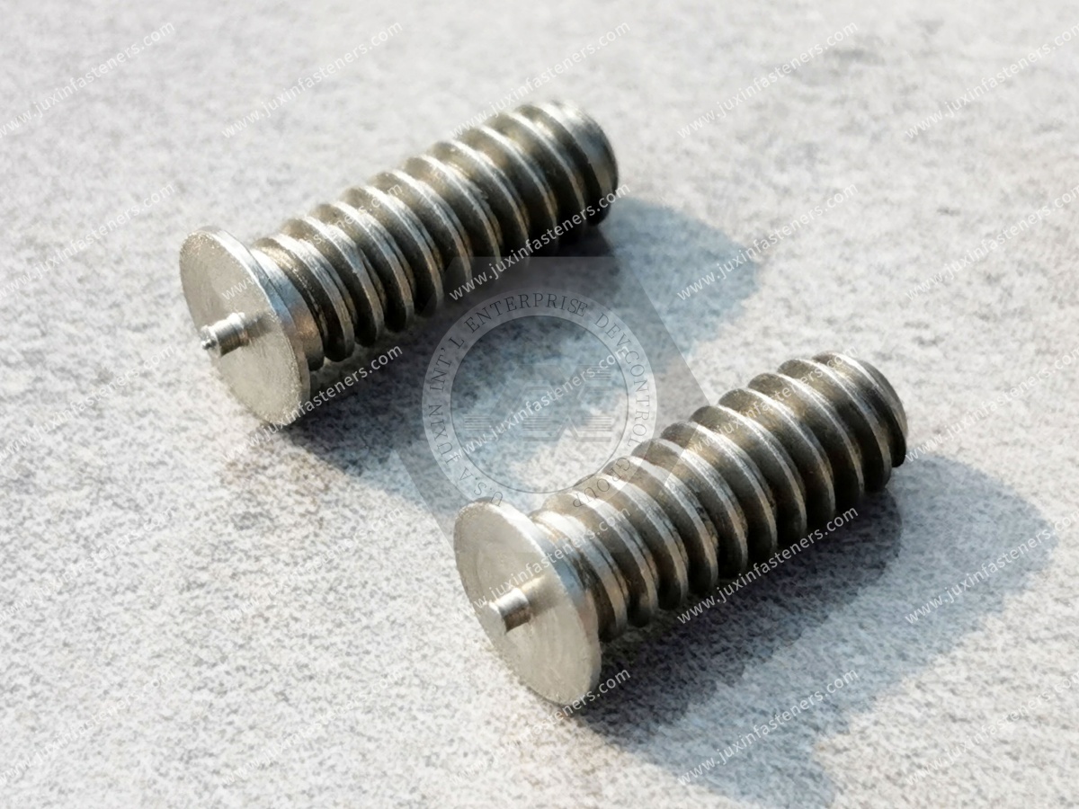
Relevant stud characteristics include:
Straightness
Overall dimensions
Welding-end geometry
Ignition-tip consistency
Material composition
Surface condition
Thread integrity
Process-Related Variables
Relevant welding conditions include:
Stored electrical energy
Current delivery characteristics
Stud movement
Contact condition
Welding gun alignment
Workpiece grounding
Fixturing
Equipment maintenance
Substrate-Related Variables
Relevant base-material conditions include:
Material grade
Sheet thickness
Surface coating
Oxidation
Oil or other contamination
Local geometry
Mechanical support
The welded joint is the result of these interacting conditions rather than the independent performance of a single component.
Stud Misalignment and Incorrect Weld Position
Misalignment is a common problem in manual and automated stud welding.
It may appear as:
A stud welded at an angle
Incorrect positioning on the workpiece
Eccentric attachment
Inconsistent stud perpendicularity
Stud Geometry and Straightness
A bent stud may affect positioning in the welding gun or automatic feeding equipment.
The influence depends on stud length, diameter, permitted straightness deviation and equipment geometry.
Longer or relatively slender studs may be more sensitive to certain positioning variations.
Welding Gun and Fixture Alignment
Even a geometrically conforming stud may be welded at an angle if the welding gun is not properly aligned with the workpiece.
Fixture movement, inconsistent workpiece positioning and insufficient mechanical support may also contribute.
Contact Geometry
An uneven initial contact condition may influence the local welding interaction.
The resulting effect depends on the welding process and stud configuration.
Engineering Significance
Stud perpendicularity can influence subsequent assembly operations, including nut installation, component clearance and alignment of mounted equipment.
In automated production, misalignment may also increase rejected assemblies or require additional adjustment.
Weak Welds and Incomplete Fusion
A weak CD stud weld may fail to achieve the mechanical performance required for the intended application.
Possible failure behavior includes separation at the welded interface or fracture in another region of the assembly.
The physical cause cannot be established from the failure load alone.
Insufficient Effective Energy at the Interface
The electrical energy available in a capacitor discharge system influences the welding process.
The nominal stored energy can be expressed as:
E = ½ CV²
Where:
E is stored electrical energy
C is capacitance
V is charging voltage
This expression describes the energy stored in the capacitor system.
It does not directly establish the energy effectively transferred into the weld interface.
Actual energy transfer depends on the electrical circuit, contact conditions and welding process.
Material and Surface Conditions
Differences in electrical and thermal properties may influence local heating and weld formation.
Surface contamination or coatings may also change the initial contact conditions.
Ignition-Tip Geometry
Certain CD weld studs incorporate an ignition tip that participates in weld initiation.
Variation in this feature may influence the initial interaction between the stud and substrate.
Mechanical Movement and Timing
The mechanical behavior of the stud during the welding cycle is another relevant variable.
The relationship between electrical discharge and stud movement affects the formation of the welded interface.
Engineering Significance
Incomplete fusion and insufficient joint strength are not interchangeable descriptions.
A weak mechanical test result may arise from several failure mechanisms, and the fracture surface and failure location provide additional information.
Ignition-Tip Defects and Inconsistent Weld Initiation
For CD weld stud designs incorporating an ignition tip, the tip is a functional welding feature.
Its geometry may affect the initial electrical and thermal interaction at the welding interface.
Potential variations include:
Missing ignition tip
Damaged tip
Incorrect tip projection
Irregular tip shape
Contamination at the welding end
These variations may influence weld initiation behavior.
However, the resulting weld quality also depends on the welding equipment, substrate and process settings.
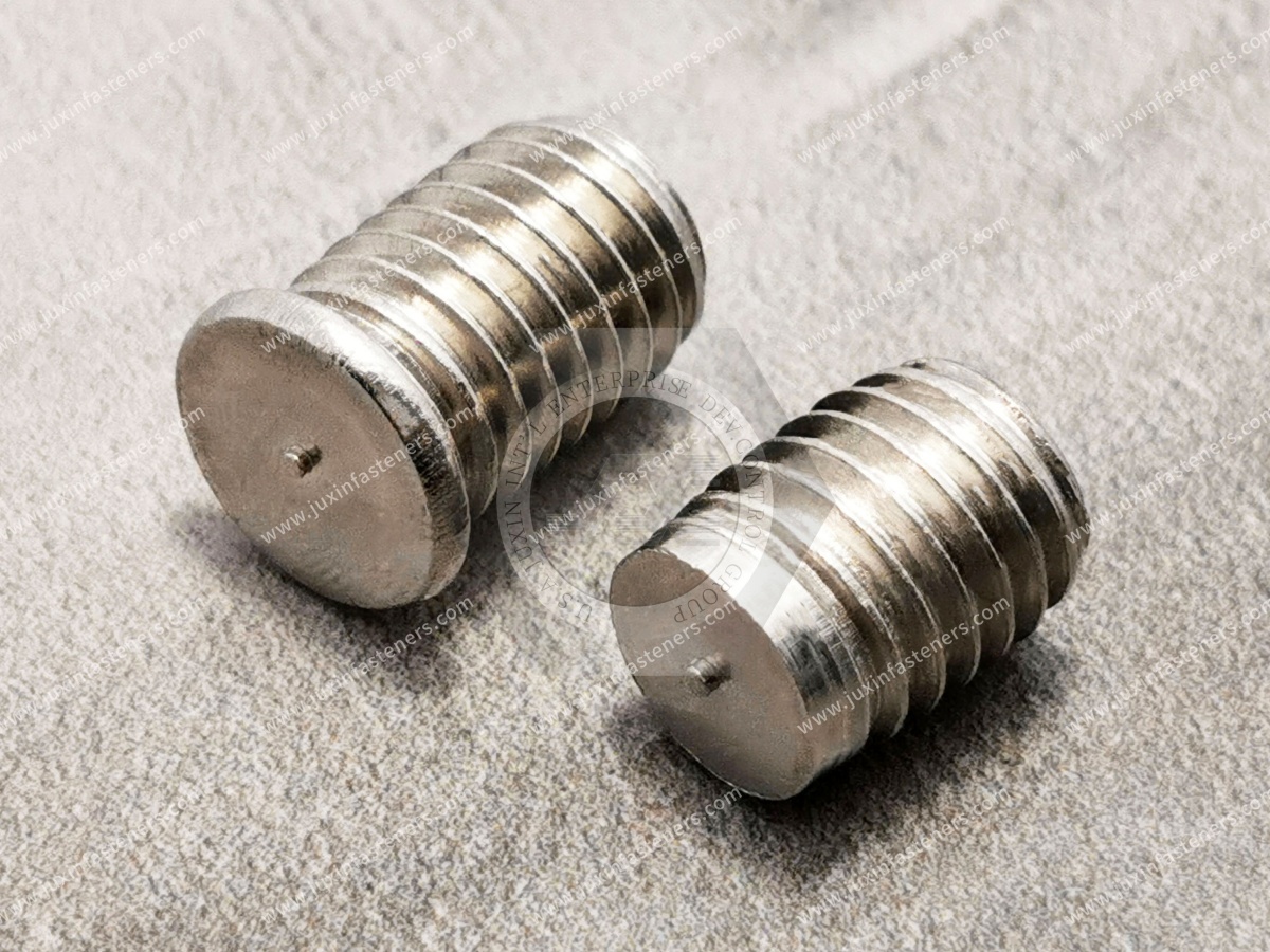
Engineering Information Gain: Tip Consistency and Weld Consistency Are Related but Not Identical
Consistent ignition-tip geometry reduces one source of component variation.
It does not eliminate variation caused by surface condition, electrical contact or equipment behavior.
For this reason, dimensional conformity and welded joint performance remain distinct technical characteristics.
Excessive Spatter and Irregular Weld Appearance
Spatter may occur during stud welding when molten material is expelled from the welding region.
The amount and distribution of spatter depend on the process conditions.
Potential contributing factors include:
Electrical discharge characteristics
Material properties
Contact condition
Surface contamination
Welding-end geometry
Mechanical interaction during the welding cycle
Excessive spatter may create problems in applications with restricted assembly clearance or appearance requirements.
However, weld appearance alone does not establish mechanical strength.
Weld Appearance vs. Weld Integrity
A visually uniform welded region does not automatically guarantee satisfactory joint performance.
Similarly, a visible weld irregularity does not by itself identify the mechanical failure mechanism.
The interpretation depends on the applicable welding specification and acceptance criteria.
Sheet-Metal Distortion, Backside Marking and Local Damage
CD stud welding is often associated with relatively short welding cycles.
Nevertheless, local thermal effects may still occur.
Possible effects include:
Backside marking
Local discoloration
Surface distortion
Local material deformation
Excessive penetration or burn-through under unsuitable conditions
These effects depend on:
Base material thickness
Stud diameter
Material properties
Welding energy
Surface condition
Workpiece support
Thin-Sheet Applications
Thin sheet-metal components may be particularly sensitive to local thermal and mechanical effects.
The relationship between stud geometry, substrate thickness and process conditions influences the resulting joint.
Engineering Information Gain: Short Welding Duration Does Not Mean Zero Thermal Effect
A short-duration welding process can limit the extent of heat input compared with some other joining processes,
but it does not guarantee the absence of reverse-side marking or local distortion.
The actual result is application-dependent.
Weld Fracture and Failure Location
Mechanical testing provides information about the behavior of the welded assembly.
Potential failure locations include:
The stud body
The welded interface
The heat-affected region
The base material
The sheet-metal region surrounding the weld
Each failure location represents a different mechanical condition.
Stud Fracture
Failure within the stud may indicate that the stud section reached its load-carrying limit under the test conditions.
Interface Separation
Separation at the welded interface may indicate that the interface did not sustain the applied loading.
However, the underlying cause requires additional examination.
Base-Material Failure
Failure in the substrate may occur when the base material becomes the limiting element of the assembly.
Engineering Significance
A maximum test load without information about failure location and test configuration provides an incomplete description of joint performance.
The loading direction, test fixture and material thickness influence the observed result.
Thread Damage and Secondary Assembly Failures
A CD weld stud may produce an acceptable welded joint while still presenting problems during subsequent assembly.
Thread-related defects may include:
Damaged thread crests
Incomplete threads
Burrs
Incorrect thread dimensions
Handling damage
These defects may affect:
Nut engagement
Assembly torque
Thread fit
Installation time
Rework requirements
The threaded connection and the welded attachment are separate functional interfaces.
Their performance requirements should not be confused.
Automated Feeding Failures and Equipment Interruptions
In automated CD stud welding, component geometry influences the feeding and positioning process.
Potential problems include:
Feeding jams
Incorrect orientation
Inconsistent stud presentation
Positioning errors
Repeated equipment adjustments
Contributing factors may include:
Stud straightness
Dimensional variation
Burrs
Packaging damage
Feeder configuration
Equipment wear
Contamination
Component Variation vs. Equipment Variation
A feeding interruption may originate from the component, equipment or their interaction.
For example, a stud may meet its drawing requirements while remaining unsuitable for a particular feeding mechanism.
Similarly, a feeding system may become less reliable because of wear or incorrect adjustment.
The distinction is important when evaluating production consistency.
Batch-to-Batch Variation in CD Weld Stud Supply
High-volume manufacturing requires repeatable component characteristics across production batches.
Potential sources of variation include:
Raw material changes
Forming-tool wear
Process adjustments
Surface condition
Handling
Packaging
Manufacturing process changes
These variations may affect geometry, welding behavior or automated handling.
Engineering Information Gain: Batch Consistency Has Both Mechanical and Production Consequences
Dimensional variation can influence positioning and feeding.
Material or surface variation can influence welding behavior.
Thread variation can affect subsequent mechanical assembly.
These are different consequences of component inconsistency and may require different forms of evaluation.
Dimensional Inspection and Welding Validation
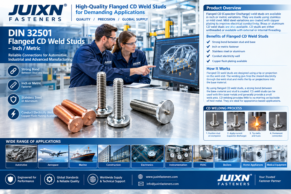
Component inspection and welding validation address different aspects of CD weld stud quality.
| Technical characteristic | Typical evaluation focus | Relationship to production |
|---|---|---|
| Straightness | Geometric conformity | Feeding and alignment |
| Thread dimensions | Thread conformity | Mechanical assembly |
| Welding-end geometry | Ignition-tip or welding feature | Weld initiation |
| Material | Specified material properties | Welding compatibility |
| Surface condition | Contamination and defects | Contact and weld behavior |
| Welded joint | Mechanical performance | Finished joint integrity |
| Production operation | Feeding and process consistency | Manufacturing reliability |
100% Inspection and Its Limitations
100% inspection means that every component is examined for specified characteristics using defined inspection methods.
It does not necessarily mean that every dimension, material property or welded joint characteristic is individually tested.
For example, visual or automated screening may be applied to selected component defects.
Other characteristics may be evaluated through dimensional sampling, material verification or representative welding tests.
Inspection effectiveness depends on the measurement method and the defects being detected.
Inspection Cannot Replace Process Stability
A sorting process may remove detectable nonconforming parts.
However, sorting does not independently establish the stability of the manufacturing process.
Component conformity and manufacturing consistency are related but distinct aspects of industrial quality control.
Welding Parameters and Electrical Contact Conditions
CD stud welding depends on controlled electrical and mechanical conditions.
Relevant factors include:
Capacitor charging voltage
Stored energy
Electrical circuit characteristics
Contact resistance
Stud movement
Welding gun condition
Workpiece grounding
Cable and connection condition
Variation in these factors may influence the energy delivered to the welding interface.
Grounding and Electrical Return Path
The electrical return path is part of the welding circuit.
Poor electrical connections or variable contact resistance may affect welding behavior.
Mechanical Positioning
The welding gun and fixture influence the relative position of the stud and substrate.
Mechanical variation can therefore contribute to inconsistent results even when the stud dimensions are within specification.
Engineering Significance
Welding process stability cannot be determined from the stud specification alone.
The complete electrical and mechanical system contributes to the final joint.
Material Compatibility and Surface Treatment
The material combination affects welding behavior.
Carbon Steel Weld Studs
Carbon steel studs may be used in suitable steel assemblies, depending on the material grade and welding requirements.
Stainless Steel Weld Studs
Stainless steel studs may be used in applications requiring selected corrosion or material characteristics.
The actual welding behavior depends on the stainless steel grade and substrate.
Coated Components
Surface coatings may affect electrical contact, local heating and weld formation.
The influence depends on coating type, thickness and process conditions.
Dissimilar Metals
Differences in thermal, electrical and metallurgical properties may complicate welding.
Material compatibility must be established for the specific joint.
Industrial Applications and Failure Sensitivity
Automotive Sheet-Metal Manufacturing
Automotive assemblies may include welded threaded attachment points in suitable sheet-metal components.
Relevant technical concerns include:
Position accuracy
Joint strength
Production repeatability
Material compatibility
Surface condition
Corrosion exposure
Applications involving safety-critical loads require the relevant engineering approval and validation.
Electrical Enclosures and Control Cabinets
CD weld studs may be used in suitable mechanical mounting applications for:
Enclosures
Internal mounting brackets
Equipment panels
Industrial cabinets
Important considerations include:
Panel thickness
Stud perpendicularity
Thread engagement
Assembly clearance
Surface finish
Electrical grounding or current-carrying applications may require additional requirements beyond mechanical weld strength.
Industrial Machinery and Fabricated Equipment
CD weld studs may be used for selected attachment points in:
Equipment housings
Fabricated panels
Machinery covers
Mounting assemblies
Industrial sheet-metal components
The appropriate stud design depends on loading, substrate material and the manufacturing process.
Relevant International Standards
ISO 13918 — Studs and Ceramic Ferrules for Arc Stud Welding
ISO 13918 addresses specified stud configurations and product requirements used in arc stud welding applications.
It is relevant to covered standardized welding stud designs.
ISO 14555 — Arc Stud Welding of Metallic Materials
ISO 14555 addresses requirements for arc stud welding of metallic materials.
It is relevant to welding procedure, examination and qualification considerations within its scope.
Component Conformity and Welded Joint Conformity
A stud conforming to an applicable product standard does not automatically establish that the welded assembly meets its mechanical requirements.
The welding process and finished joint must satisfy the applicable customer and process specifications.
Metric and Inch Thread Systems
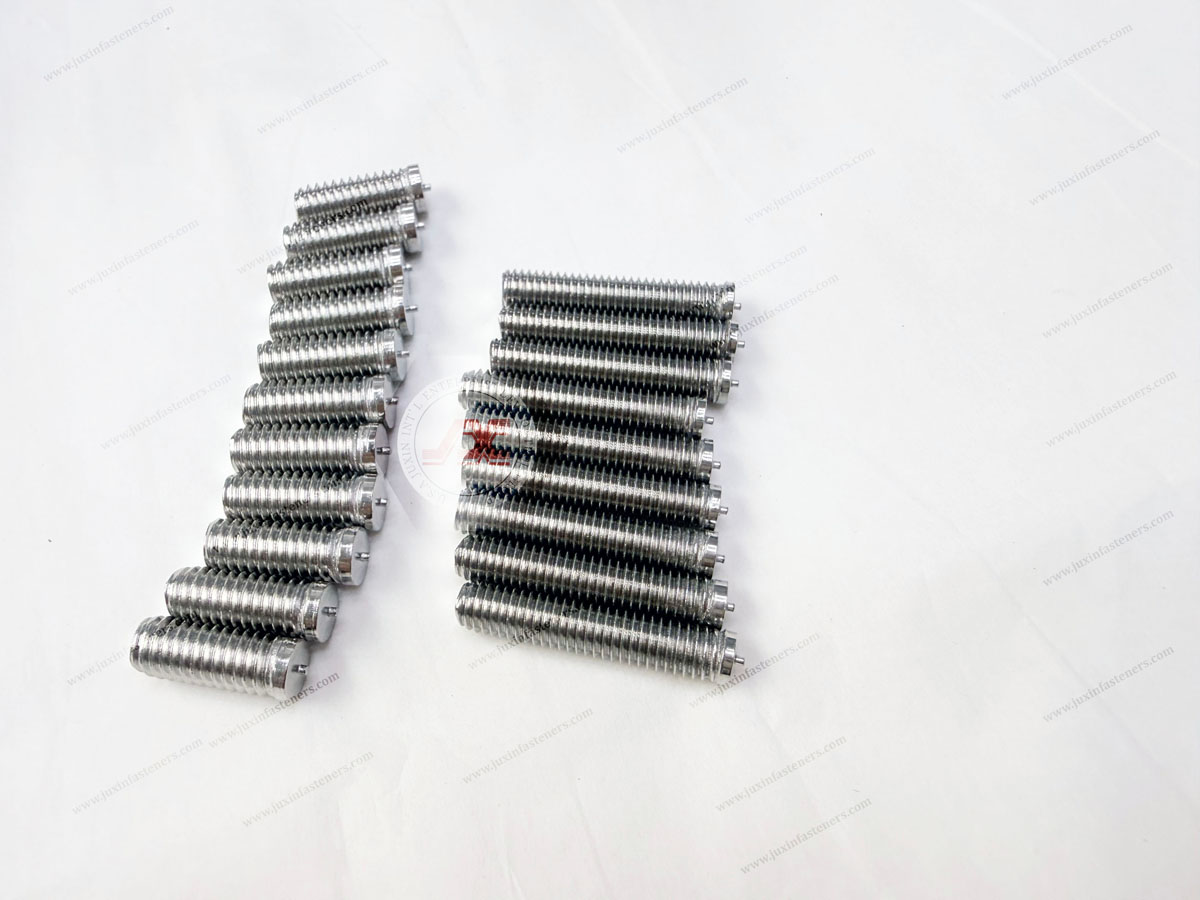
CD weld studs may be specified with metric or inch-series threads, depending on the approved design and actual supply configuration.
Metric, UNC, UNF, BSW and BSF thread systems are different and must not be treated as directly interchangeable.
Thread compatibility depends on the complete thread specification.
Production Reliability and Total Manufacturing Cost
The commercial impact of CD weld stud defects extends beyond the purchase price of the fastener.
Potential manufacturing costs include:
Production interruptions
Equipment adjustments
Incoming sorting
Rejected welded assemblies
Rework
Scrap
Additional inspection
Delayed deliveries
Cost per Accepted Welded Assembly
The cost of a finished acceptable assembly depends on both component price and manufacturing performance.
A lower unit price may not reduce overall production cost if it is associated with higher rejection or interruption rates.
Conversely, additional inspection and quality requirements also have costs and must correspond to the application's actual risk.
For volume manufacturing, the interaction between component consistency, welding process capability and assembly yield is therefore commercially significant.
CD Weld Stud Specifications for OEM Manufacturing
Technical specifications for CD weld studs may include:
| Specification area | Relevant requirements |
|---|---|
| Stud configuration | Externally threaded, internally threaded or custom design |
| Drawing | 2D/3D drawing and revision |
| Standard | Applicable ISO or customer specification |
| Thread | Diameter, pitch and tolerance |
| Dimensions | Length, straightness and welding-end geometry |
| Material | Required grade |
| Base material | Alloy, thickness and surface condition |
| Welding process | Equipment and process conditions |
| Joint performance | Required loading and acceptance criteria |
| Inspection | Defined characteristics and methods |
| Documentation | Material and inspection records |
| Packaging | Protection of threads and welding features |
| Supply | Prototype quantity, annual demand and delivery schedule |
These requirements connect component design, manufacturing consistency and commercial sourcing.
CD Weld Stud Solutions from Juxin Fasteners
Juxin Fasteners has more than 20 years of experience serving international industrial fastening customers.
Our fastening product portfolio includes:
CD weld studs
DIN 34817 weld studs
Weld nuts
Self-clinching fasteners
Blind rivet nuts
Industrial nuts and threaded fasteners
Rivets
Custom drawing-based OEM fastening components
CD weld stud projects may involve different thread specifications, materials, dimensions, welding features and inspection requirements.
Specific product availability, manufacturing feasibility, inspection arrangements, documentation, MOQ and lead times are confirmed according to the submitted project requirements.
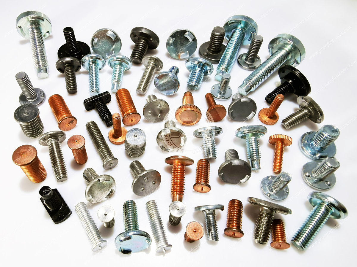
CD Weld Stud OEM RFQ and Technical Inquiry
Juxin Fasteners welcomes inquiries for CD weld studs used in automotive components, electrical enclosures, industrial sheet-metal assemblies and automated manufacturing.
Technical information relevant to quotation includes:
2D/3D drawings and revision
Applicable standard
Stud configuration
Material grade
Metric or inch thread specification
Overall dimensions and tolerances
Ignition-tip or welding-feature geometry
Base material and sheet thickness
Welding equipment or process requirements
Mechanical loading requirements
Inspection and documentation requirements
Prototype quantity and annual demand
Packaging and delivery schedule
Company: Juxin Fasteners
Website: https://www.juxinfasteners.com/
Email: info@juxinfasteners.com
For CD weld stud technical specifications, custom fastening drawings and OEM volume inquiries,
contact Juxin Fasteners for feasibility review and quotation.
Contact Us
Tel.:
+86 020 8621 0320
+86 020 3121 6067
E-mail:
Technical Support:
Navigation
SEND INQUIREY



