
Call Us
+86 136 6007 9809
Call Us
+86 136 6007 9809

Nov. 04, 2023
ISO 8734 parallel pins are precision cylindrical locating components used to establish accurate and repeatable positional relationships between mating machine parts.
They are commonly described in industrial sourcing as ISO 8734 parallel pins, hardened dowel pins, hardened and ground parallel pins, precision dowel pins, or cylindrical locating pins.
Their primary engineering function is different from that of bolts and screws.
A threaded fastener is normally selected primarily to generate clamping force.
An ISO 8734 parallel pin is selected primarily to establish or maintain location between components and, where the joint is designed accordingly, may also participate in shear load transfer.
Typical applications include:
Machine housings
Gearbox assemblies
Industrial automation
Automotive manufacturing equipment
Jigs and fixtures
Machine tools
Molds and dies
Precision mechanical assemblies
JUXIN FASTENERS supplies ISO 8734 parallel pins, hardened dowel pins, precision ground locating pins and drawing-based custom pins for OEM and industrial applications.
For engineering and procurement teams, the most important principle is that the pin cannot be specified in isolation.
The functional system is:
pin standard → pin diameter tolerance → mating-hole tolerance → hole position → fit → material and hardness → engagement → assembly method → inspection
An ISO 8734 parallel pin is a hardened cylindrical pin intended for precision locating and related mechanical assembly functions.
The cylindrical outside diameter is manufactured with controlled dimensional accuracy and surface condition so that the pin can work with appropriately toleranced mating holes.
Depending on the joint design, ISO 8734 pins may be used to:
Locate mating components
Maintain alignment
Establish repeatable assembly position
Create a mechanical datum
Resist relative lateral movement
Participate in shear load transfer
Support repeatable maintenance and reassembly
The actual performance depends not only on the pin but also on the mating holes and complete assembly geometry.
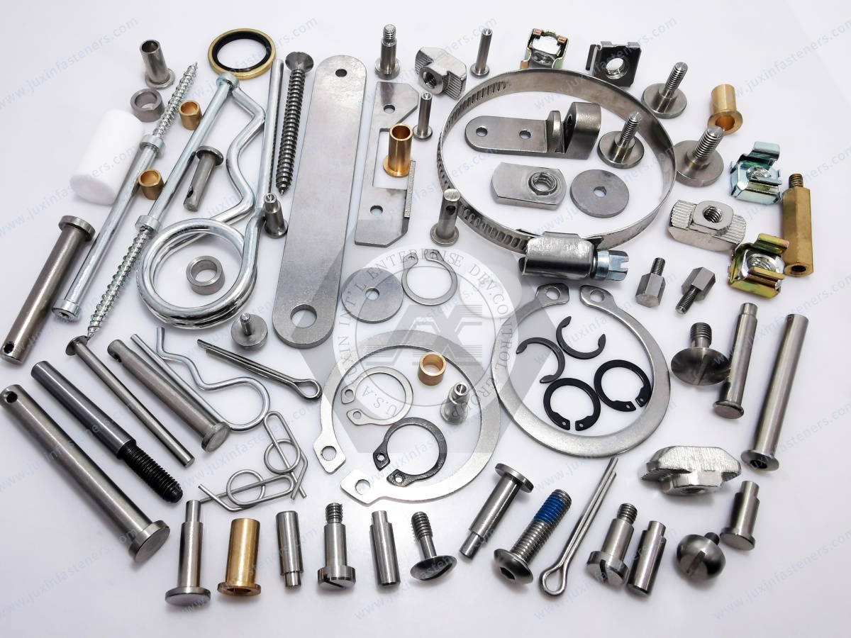
Different markets use different terminology.
Parallel pin is common in ISO and European industrial sourcing.
Dowel pin is widely used in North American engineering and purchasing.
Cylindrical pin is another common technical description.
For international SEO and procurement, all three terms are relevant.
However, the governing specification should be the actual ISO 8734 requirement or customer drawing, not the commercial name alone.
Not every precision dowel pin is an ISO 8734 pin.
“Precision dowel pin” is a broad product description that can include:
Standard hardened pins
Unhardened pins
Stainless pins
Internally threaded pins
Stepped locating pins
Customer-specific ground pins
Special-tolerance pins
ISO 8734 defines a particular standardized parallel-pin family.
If a customer requires ISO 8734, the supplier should verify the specified standard rather than supplying any dimensionally similar dowel pin.
For broader dowel-pin selection, see our Precision Dowel Pins engineering guide.
ISO 8734 is commonly associated with hardened and ground parallel pins used for accurate locating.
Hardening can provide the material condition required for the specified product, while grinding provides controlled outside diameter and surface condition.
This combination is particularly useful where the pin interacts repeatedly with accurately machined mating holes.
Relevant product characteristics can include:
Outside diameter
Diameter tolerance
Length
End geometry
Surface condition
Hardness
Material
Straightness
Roundness
The exact acceptance requirements should follow the applicable ISO standard and purchase specification.
One of the most important purchasing details for a precision parallel pin is the diameter tolerance designation.
Commercial ISO 8734 sourcing may include m6 and h6 tolerance executions, depending on the required product and application.
These designations matter because they affect how the pin interfaces with the mating hole.
A buyer should therefore avoid ordering only:
“ISO 8734, 10 × 30”
when the application also requires a specific tolerance execution.
A better purchasing description identifies:
standard + diameter + length + tolerance execution + material + any required documentation
The engineering drawing remains the controlling source where additional requirements apply.
Specifying an m6 or h6 pin does not by itself tell the engineer whether the assembled joint will be interference, transition or clearance fit.
The actual fit results from the relationship between:
pin tolerance + hole tolerance
Other factors can also influence assembly behavior:
Surface finish
Roundness
Hole manufacturing process
Material
Engagement length
Temperature
Coatings or surface condition
Measurement method
This is why copying the pin tolerance from a catalog without designing the mating hole can produce an assembly that is either too loose or too difficult to assemble.
The first question should not be:
“Which tolerance is better?”
The correct question is:
What function must this pin-and-hole interface perform?
The designer should establish whether the pin must:
Remain permanently retained in one component
Allow the second component to be removed
Provide highly repeatable positioning
Be replaced during service
Operate across a temperature range
Carry specified transverse loading
Only then should the pin and mating-hole tolerance combination be selected.
There is no universal m6-versus-h6 answer for every assembly.
Many practical dowel-pin assemblies need two different interface behaviors.
The pin may need to remain securely located in one component while the mating component must still be removable for service.
This can lead to a strategy such as:
fixed side → controlled retaining fit
removable side → controlled locating fit that permits assembly/disassembly
The exact tolerances depend on the design.
The important principle is that both holes do not automatically need the same fit.
This is especially relevant in:
Gearbox housings
Machine covers
Tooling plates
Fixtures
Serviceable mechanical equipment
Precision engineering does not mean making every tolerance as tight as possible.
An unnecessarily tight fit can create:
Excessive insertion force
Difficult assembly
Difficult disassembly
Damage to mating holes
Pin damage
Increased machining cost
Higher scrap risk
An unnecessarily loose fit can create:
Reduced locating repeatability
Positional movement
Alignment variation
The correct objective is functional fit, not minimum clearance.
ISO 8734 and ISO 2338 should not be treated as interchangeable names for the same product.
ISO 8734 is associated with hardened parallel pins.
ISO 2338 covers unhardened parallel pins.
That difference matters.
A sourcing team should not substitute an ISO 2338 pin for an ISO 8734 pin solely because the nominal diameter and length are the same.
The design may depend on:
Material condition
Hardness
Wear behavior
Dimensional execution
Application requirements
Where the drawing specifies ISO 8734, deviations should be technically reviewed before substitution.
DIN 6325 is frequently encountered on legacy drawings and older machinery.
However, procurement teams should not automatically assume that DIN 6325 and ISO 8734 are dimensionally identical in every respect.
When converting a legacy DIN 6325 requirement to ISO 8734, review:
Pin diameter
Length
End geometry
Tolerance
Material
Hardness
Mating-hole design
Existing assembly
A legacy drawing should therefore be evaluated before changing the standard designation.
This is particularly important during second-source development and replacement-part sourcing.
ISO 8735 addresses hardened parallel pins with an internal thread.
The internal thread provides an extraction feature that can be useful where a pin is installed in a blind hole or must be removed during service.
The practical distinction is:
ISO 8734 → solid hardened parallel pin
ISO 8735 → hardened parallel pin with internal thread for extraction
If removal from a blind hole is important, an internally threaded design may be more appropriate.
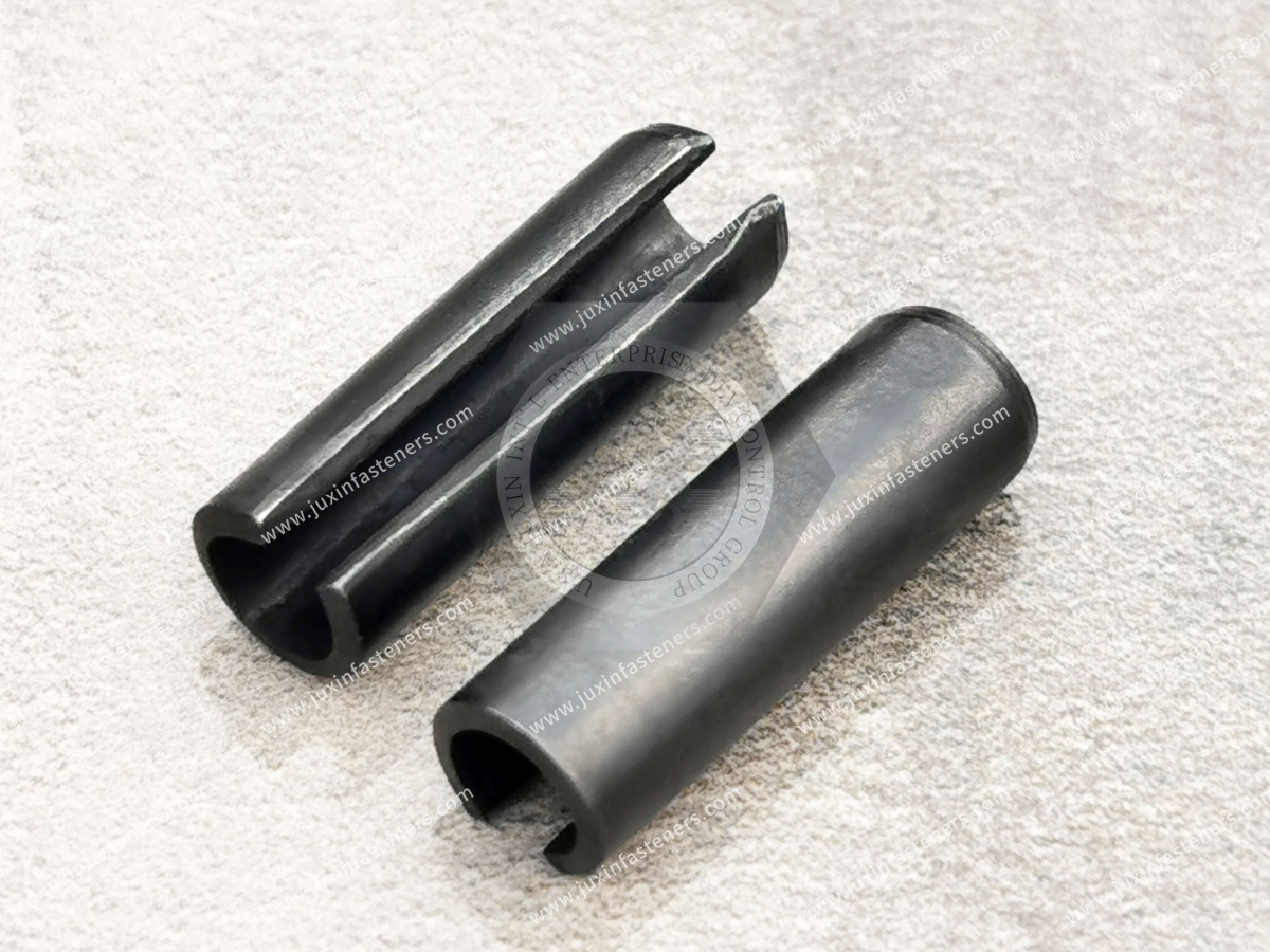
ISO 8734 parallel pins and spring pins belong to different engineering families.
An ISO 8734 parallel pin relies on precision cylindrical geometry and controlled mating-hole fits.
A spring pin elastically compresses during installation and exerts radial force against the hole.
Spring pins may reduce some hole-precision requirements and provide useful retention characteristics, but they do not behave like a precision ground solid locating pin.
Selection depends on:
Positioning accuracy
Installation method
Hole preparation
Load
Vibration
Serviceability
Cost
A parallel pin has a cylindrical working diameter.
A taper pin uses corresponding tapered geometry.
Both can be used for locating, but the mating-hole preparation and seating behavior are different.
A taper pin should therefore not be treated as a direct substitute for an ISO 8734 parallel pin.
ISO 8734 sourcing should follow the material and hardness requirements defined by the applicable standard and customer specification.
For OEM purchasing, avoid replacing the required material with a generic statement such as:
“high-strength steel”
or
“alloy steel”
without confirming equivalence.
Important purchasing information can include:
Standard
Material execution
Hardness requirement
Surface condition
Diameter tolerance
Required documentation
Where a customer needs a different material or corrosion-resistant solution,
the resulting part may need to be handled as a specified alternative or custom locating pin rather than automatically described as a standard ISO 8734 steel pin.
Corrosion-sensitive equipment may require a stainless locating pin.
However, changing a standard hardened steel ISO 8734 pin to stainless steel is not simply a cosmetic material substitution.
The change can affect:
Hardness
Wear
Fit behavior
Surface condition
Galling tendency
Mating-material compatibility
Corrosion behavior
Therefore, the engineering requirement should be reviewed before substituting material.
For non-standard stainless or special-material locating pins, JUXIN FASTENERS can manufacture according to customer drawings and specifications.
A precision ground locating diameter is a functional surface.
Adding a coating can alter the effective diameter and fit.
This is particularly important where tight pin-and-hole relationships are involved.
Before applying a custom coating to a precision pin, engineers should consider:
Coating thickness
Dimensional buildup
Uniformity
Surface roughness
Wear
Installation
Corrosion requirement
A coating should not be added to an ISO 8734 pin simply because the same coating is commonly used on bolts.
The locating function must be protected.
Machine-tool assemblies require repeatable positional relationships between components.
Parallel pins may be used for:
Housing alignment
Fixture location
Tooling plates
Machine subassemblies
Removable components
The pin can establish location while threaded fasteners provide clamping.
This separation between locating and clamping is central to precision machine design.
Automation equipment frequently requires repeatable component positioning during assembly, maintenance and changeover.
Applications can include:
Robotic fixtures
Assembly stations
Tooling
Machine frames
Actuator mounting structures
Changeover systems
ISO 8734 parallel pins can provide a standardized locating solution where their geometry and tolerance meet the design requirements.
For custom automation tooling, special locating-pin geometry may be more appropriate.
ISO 8734 pins can be used in automotive manufacturing equipment and mechanical assemblies requiring controlled location.
Applications may include:
Production fixtures
Welding jigs
Inspection fixtures
Gearbox-related assemblies
Housing alignment
Manufacturing equipment
The required pin should be selected according to the actual vehicle-component or production-equipment drawing.
Automotive use alone does not define the correct diameter, tolerance or material.
Molds, dies and tooling frequently depend on repeatable component location.
Parallel pins can support:
Tooling-plate alignment
Die assembly
Mold-component location
Replaceable tooling
Fixture positioning
Important considerations include:
Fit
Wear
Hardness
Repeated assembly
Removal strategy
Hole accuracy
If frequent extraction is required from a blind hole, an internally threaded locating pin may provide better serviceability.
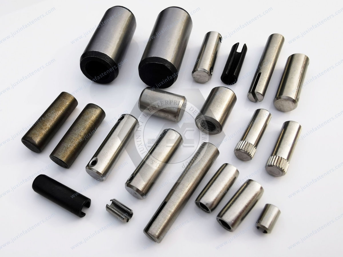
Parallel pins are commonly used to maintain relative position between housing sections and mechanical components.
A properly designed locating system can help restore the intended assembly position after maintenance.
However, the pin cannot compensate for poor machining of:
Mating faces
Hole locations
Bearing bores
Datums
The complete tolerance architecture still determines assembly accuracy.
They can participate in shear load transfer when the joint is specifically designed for that function.
But a designer should not assume that every locating pin carries all lateral load in an assembly.
The actual load path may involve:
Joint friction from bolt preload
One or more dowel pins
Shoulders
Keys
Other locating features
If the pin is structurally loaded, engineering analysis should consider:
Pin diameter
Material
Hardness
Shear planes
Bearing stress
Mating material
Hole geometry
Static and cyclic loading
Locating and structural load transfer should be evaluated separately.
Two parallel pins are often used to control translation and rotation between mating parts.
However, two tightly constrained round-pin interfaces can create assembly problems if the positional tolerances are not coordinated.
The design should consider:
Pin spacing
Hole spacing
Position tolerance
Fit
Thermal expansion
Manufacturing capability
The fact that both pins individually meet ISO dimensional requirements does not guarantee that the complete two-pin assembly will fit.
This is a critical distinction between component conformity and assembly functionality.
Precision fits can change with temperature.
If the pin and mating components have different coefficients of thermal expansion, operating temperature may change the effective clearance or interference.
This can matter in:
Precision machinery
Heated equipment
Outdoor machinery
Dissimilar-material assemblies
Equipment with large temperature cycles
Where temperature variation is significant, fit should be evaluated across the expected operating range.
A hardened precision pin requires controlled manufacturing processes.
Depending on the material, size and production route, operations may include:
Forming or machining
Heat treatment
Grinding
Diameter control
End finishing
Cleaning
Inspection
The finished locating diameter is a critical functional feature.
For high-volume production, process capability should be established around the characteristics required by the standard and purchase specification.
Grinding is important because the pin diameter directly affects the mating fit.
Inspection may therefore need to consider:
Diameter
Roundness
Straightness
Surface condition
Length
End geometry
A nominally correct diameter is not sufficient if the surface or geometry prevents proper assembly.
For custom precision pins, additional geometric controls may be specified on the drawing.
Inspection should be based on the applicable ISO standard and customer purchase requirements.
Depending on the project, controls may include:
Diameter
Length
Diameter tolerance execution
Material
Hardness
Surface condition
End geometry
Visual inspection
Packaging and identification
Required material documentation
For OEM programs, inspection documentation should be agreed during quotation rather than assumed after production.
This can omit the required tolerance execution, material or other functional requirements.
Many precision pins follow other standards or customer drawings.
Legacy-standard conversion requires technical review.
Unhardened and hardened parallel pins should not be treated as automatically equivalent.
Coating buildup can change the locating diameter.
The pin alone cannot define the assembled fit.
Hole position, spacing and assembly tolerances remain critical.
Use a standard ISO 8734 pin when:
Standard geometry fits the application
Standard tolerance meets the locating requirement
Standard material condition is appropriate
No special extraction or geometry is required
Consider a custom precision pin when the application requires:
Special diameter
Special tolerance
Stepped geometry
Shoulder
Internal or external thread
Special material
Special end geometry
Custom hardness
Restricted assembly envelope
Drawing-controlled features
A custom part should solve a functional requirement rather than simply deviate from a standard unnecessarily.
For supplier development, a practical qualification path is:
Verify the exact ISO designation and drawing revision.
Identify the required diameter tolerance.
Do not qualify based only on dimensions.
Understand whether the pin is used for locating, retention, shear transfer or multiple functions.
Check dimensional conformity and installation behavior.
Confirm fit, repeatability and serviceability where appropriate.
Define inspection, documentation, packaging and traceability requirements.
This process is especially important when the parallel pin establishes a critical machine datum.
For accurate quotation and technical review, provide:
ISO 8734 designation
Nominal diameter
Length
Required tolerance execution
Material requirement
Hardness requirement where specified
Surface condition
Customer drawing, if applicable
Mating-hole information for fit-sensitive applications
Application
Operating environment
Inspection requirements
Material documentation requirements
Sample quantity
Production quantity
Estimated annual demand
Packaging requirements
For replacement or second-source projects, providing the existing drawing and sample can improve technical review.
ISO 8734 parallel pins are commonly described as hardened dowel pins or precision locating pins. However, “dowel pin” is a broader product category and not every dowel pin conforms to ISO 8734.
ISO 8734 is associated with hardened parallel pins. The required material and hardness should be confirmed against the applicable standard and purchasing specification.
ISO 8734 covers hardened parallel pins, while ISO 2338 covers unhardened parallel pins. They should not be substituted solely on the basis of nominal diameter and length.
They are closely related legacy/current product families encountered in the market, but they should not automatically be treated as dimensionally identical.
Existing drawings and mating assemblies should be reviewed before substitution.
ISO 8735 covers hardened parallel pins with an internal thread, providing an extraction feature useful for certain blind-hole and serviceable applications.
m6 is a shaft tolerance designation controlling the permissible diameter variation relative to nominal size.
The resulting assembly fit also depends on the mating-hole tolerance.
An H7 hole is one possible mating-hole tolerance encountered in precision locating systems, but the resulting fit depends on the pin tolerance execution, nominal size and application.
Engineers should evaluate the actual tolerance combination rather than treating H7 as a universal hole requirement.
A coating can alter the functional diameter and surface condition. Any coating requirement should therefore be reviewed against the standard, required fit and customer drawing.
Yes. Where a project requires non-standard dimensions, special materials, different tolerances or additional features, JUXIN FASTENERS can review drawing-based custom precision pin requirements.
An ISO 8734 pin is a standardized precision component, but successful application still depends on the surrounding assembly.
The engineering decision path is:
locating function → standard → tolerance execution → mating hole → fit → material/hardness → installation → validation
The procurement path is:
ISO designation → size → tolerance → material → documentation → sample → assembly verification → production
Keeping these two paths connected helps prevent a common industrial sourcing problem: purchasing a pin that matches the nominal catalog dimensions but does not reproduce the required assembly behavior.
JUXIN FASTENERS supplies ISO 8734 parallel pins, hardened dowel pins, precision ground locating pins and custom precision pins for industrial machinery,
automotive manufacturing, automation, tooling, molds and dies, and OEM equipment.
For standard ISO 8734 requirements, replacement parts, second-source projects or custom locating pins, send your specification, 2D drawing, 3D model or sample for technical review and quotation.
JUXIN FASTENERS
FASTENING SOLUTIONS FOR GLOBAL OEMS
Website: www.juxinfasteners.com
Email: info@juxinfasteners.com
 MORE NEWS

Sep. 27, 2026

Sep. 27, 2026

Sep. 27, 2026
Contact Us
Tel.:
+86 020 8621 0320
+86 020 3121 6067
E-mail:
Technical Support:
Navigation
SEND INQUIREY