Call Us
+86 136 6007 9809
Call Us
+86 136 6007 9809

How do cyclic mechanical loads and vibration affect the fatigue strength of welded fastener joints?
Fastener fatigue strength under cyclic loading is determined by the interaction between alternating stress, mean stress,
joint stiffness, preload, fastener geometry, weld-interface integrity, parent-sheet behavior, surface condition, and the actual operating environment.
Product Specification
How do cyclic mechanical loads and vibration affect the fatigue strength of welded fastener joints?
Fastener fatigue strength under cyclic loading is determined by the interaction between alternating stress, mean stress, joint stiffness, preload, fastener geometry,
weld-interface integrity, parent-sheet behavior, surface condition, and the actual operating environment.
Unlike a static tensile or proof-load test, fatigue loading can cause progressive damage over a large number of cycles even when the maximum applied load remains below the material's static yield strength.
For this reason, a weld nut, weld stud, or other welded fastener should not be evaluated only by its nominal static mechanical capacity.
In automotive, industrial machinery, agricultural equipment, electrical equipment, transportation systems, and other dynamic applications, welded fasteners may experience:
Repeated tensile and compressive loading
Alternating shear loads
Bending moments
Harmonic vibration
Random vibration
Shock loading
Joint slip or micro-movement
Thermal cycling combined with mechanical cycling
Variable-amplitude loading
Preload fluctuations
Local deformation of the parent sheet
The engineering objective is therefore not simply to select the “strongest” weld fastener. The objective is to establish a repeatable load path in which the fastener,
weld interface, parent sheet, mating bolt, and surrounding structure work together under the expected loading spectrum.
A useful fatigue-analysis concept can be represented as:
   [ Alternating Cyclic Stress (σa) ]
                    |
                    v
          [ Dynamic Load Path ]
                    |
          +---------+---------+
          |                   |
          v                   v
 [ Fastener / Thread ]   [ Weld Interface ]
          |                   |
          +---------+---------+
                    |
                    v
       [ Parent Sheet / Structure ]
                    |
                    v
        [ Local Stress Concentration ]
                    |
                    v
          [ Crack Initiation ]
                    |
                    v
       [ Progressive Crack Growth ]
                    |
                    v
          [ Fatigue Failure ]
For welded fastener assemblies, the critical fatigue location may not be the fastener itself. Depending on the joint configuration, failure may initiate at:
The weld interface
The projection-weld region
The parent sheet
The fastener shank
The threaded section
A geometric transition
A local bending region
A hole or opening adjacent to the fastener
A coating or surface condition that creates a stress or corrosion-related weakness
Engineering teams and test-validation managers should therefore evaluate the complete joint system and load path, rather than relying solely on a static proof-load rating.
JUXIN FASTENERS supports OEM and industrial sourcing projects by combining fastener geometry, material selection, welding considerations, application requirements,
and production requirements during the engineering and RFQ process.
Under operational conditions, fasteners seldom experience purely static loads.
Instead, they may experience fluctuating stresses defined by:
Maximum stress, σmax
Minimum stress, σmin
Mean stress, σm
Stress amplitude, σa
The stress amplitude can be represented conceptually as:
σa = (σmax − σmin) / 2
while the mean stress is:
σm = (σmax + σmin) / 2
These values help engineers understand how a cyclic load is distributed around the operating stress level.
Two joints experiencing the same nominal peak load may have significantly different fatigue behavior if their preload, stiffness, geometry, contact conditions, or local stress concentrations differ.
Fatigue performance is commonly evaluated using an S-N curve, which relates stress amplitude to the number of cycles associated with a defined fatigue criterion.
The exact S-N relationship depends on:
Material
Heat treatment
Surface condition
Geometry
Stress ratio
Loading mode
Manufacturing process
Test method
Environmental conditions
Failure criterion
Therefore, an S-N curve should not automatically be transferred from one fastener geometry or joint configuration to another.
For OEM applications, engineers should establish whether the available fatigue data represents:
The fastener material itself
The welded fastener
The complete welded joint
The parent sheet
The assembled bolted joint
A representative production configuration
This distinction is critical because the weakest component of the complete load path may determine actual fatigue life.
The boundary between a projection weld nut or weld stud and the parent sheet represents a geometric and metallurgical transition.
Such transitions can create local stress concentrations.
Potential contributors include:
Projection geometry
Weld nugget shape
Local sheet deformation
Fastener-to-sheet geometry
Sharp radii
Changes in section thickness
Hole geometry
Edge proximity
Misalignment
Weld asymmetry
Local bending
The theoretical stress concentration factor, Kt, describes the effect of geometry on local stress concentration.
In real manufactured joints, the fatigue response can also be influenced by surface condition, residual stress, material microstructure, weld quality, and manufacturing variation.
Therefore, fatigue design should not treat Kt as a single universal value for every weld fastener.
Fatigue failure generally involves a progression from local damage to crack initiation and subsequent crack growth.
A simplified sequence is:
Cyclic Loading
      ↓
Local Stress / Strain Concentration
      ↓
Microstructural Damage
      ↓
Micro-Crack Initiation
      ↓
Stable Crack Propagation
      ↓
Critical Crack Growth
      ↓
Final Fracture
The number of cycles spent in each stage can vary substantially according to material, geometry, stress level, surface condition, environment, and loading spectrum.
To improve fatigue performance of welded fastener assemblies, engineering teams should evaluate the following design factors together.
Joint preload is one of the most important variables in a bolted assembly subjected to cyclic loading.
Maintaining an appropriate clamp force can reduce the portion of external cyclic tensile loading that directly fluctuates through the fastener.
The basic engineering principle is that the external load is shared between the fastener and the clamped components according to the stiffness characteristics of the joint.
An adequately designed joint can therefore behave very differently from a poorly clamped joint subjected to the same external load.
However, preload should not be treated as “higher is always better.”
Excessive tightening can introduce:
Fastener tensile stress
Thread damage
Weld-interface loading
Parent-sheet deformation
Local bearing stress
Thread stripping
Embedment or relaxation
Coating-related friction variation
The appropriate tightening requirement must be determined from the bolt, nut, joint geometry, material, friction conditions, customer specification, and required preload.
Preventing excessive localized panel flexing under cyclic vibration can reduce secondary bending moments acting on a welded stud or nut.
A flexible sheet may transform a nominally axial load into a combined:
Tensile load
Shear load
Bending load
This is especially important for brackets, thin sheet structures, covers, equipment panels, and assemblies exposed to repeated vibration.
The so-called oil-canning effect is one example of local panel deformation that may increase dynamic movement.
Therefore, engineers should assess the surrounding sheet structure rather than analyzing the fastener in isolation.
Weld studs are particularly sensitive to bending when the applied load is offset from the weld interface.
If the external load acts at a distance from the supporting sheet, the resulting bending moment can become significant:
M = F × L
where:
M = bending moment
F = applied force
L = load eccentricity
Reducing unnecessary eccentricity can reduce the bending demand imposed on the weld interface and parent sheet.
This can be achieved through:
Better bracket geometry
Reduced unsupported length
Improved component alignment
Appropriate stud length
Adequate structural support
More favorable load introduction
Fatigue-sensitive designs should avoid abrupt geometry transitions where practical.
Engineering review should consider:
Thread runout
Fillets and radii
Flange transitions
Projection geometry
Hole edges
Sheet openings
Bracket corners
Local stamping features
Weld locations
A fastener with high static strength can still have limited fatigue performance if the surrounding structure creates a severe local stress concentration.
A weld nut or weld stud does not derive its load capacity solely from the bulk strength of the fastener.
The actual load path can include:
Mating Bolt → Thread → Fastener Body → Weld Interface → Parent Sheet → Surrounding Structure
A fatigue assessment should therefore consider every stage of this load path.
Possible limiting locations include:
Weld nugget
Projection-weld region
Parent sheet
Fastener body
Thread
Bracket
Surrounding sheet structure
In thin or highly loaded sheet-metal assemblies, the parent sheet can become the limiting component.
Possible failure mechanisms include:
Local sheet cracking
Tear-out
Hole enlargement
Plastic deformation
Local buckling
Weld-region fatigue cracking
Edge cracking
Increasing fastener strength alone does not necessarily solve these problems.
If the parent sheet is the weakest element, changing to a stronger fastener may have little effect on system fatigue life.
Resistance projection welding creates a fused joint between the fastener projections and the parent sheet.
Fatigue performance can be influenced by:
Projection geometry
Weld current
Electrode force
Weld time
Hold conditions
Material combinations
Surface condition
Nugget formation
Electrode alignment
Process repeatability
These welding variables must be developed for the specific fastener and substrate combination.
Universal welding parameters should not be assumed across different materials, thicknesses, fastener geometries, or welding equipment.
A weld fastener can pass a static pull-out or torque test and still require additional fatigue validation.
Static testing primarily answers a question such as:
“What load can this joint withstand under the defined test condition?”
Fatigue testing asks a different question:
“How does the joint behave when that load is repeatedly applied over a defined number of cycles and loading spectrum?”
For dynamic OEM applications, both types of evidence may be necessary.
Vibration can cause relative movement between components.
If the joint loses sufficient preload or experiences repeated transverse movement, the mating bolt can rotate or otherwise lose clamp force depending on the joint design and friction conditions.
This is a joint loosening problem, which is related to but distinct from material fatigue.
Fatigue concerns progressive damage under repeated stress cycles.
A joint can therefore experience:
Fatigue without visible bolt loosening
Loosening followed by increased fatigue loading
Fretting and fatigue
Parent-sheet deformation
Weld-interface cracking
The failure mode must be identified before selecting a corrective action.
Square weld nuts, hexagonal weld nuts, flanged weld nuts, tab weld nuts, and other geometries can provide different levels of rotational restraint during assembly.
However, anti-rotation geometry should not be treated as an automatic solution to fatigue.
Fatigue performance depends on the complete joint, including:
Weld attachment
Bolt preload
Joint stiffness
External load
Surface friction
Fastener geometry
Parent-sheet stiffness
Environmental exposure
Different industrial applications produce different fatigue loading profiles.
Automotive assemblies may experience combinations of:
Road-induced vibration
Suspension loads
Braking loads
Acceleration
Cornering
Powertrain vibration
Repeated body deformation
A chassis or body application therefore requires application-specific durability validation.
Construction and agricultural equipment may experience:
Shock loads
Random vibration
Repeated impact
Structural flexing
Uneven terrain
High-cycle operating vibration
Low-cycle severe loading events
The appropriate fatigue methodology depends on the actual duty cycle rather than the product category alone.
Electrical cabinets, control panels, HVAC equipment, and industrial enclosures may experience:
Fan vibration
Compressor vibration
Transportation vibration
Repeated service access
Bracket loading
Thermal cycling
The required weld fastener design depends on whether the fastener supports a light internal component or a significantly loaded structural bracket.
Battery systems and energy equipment can combine:
Mechanical vibration
Thermal cycling
Structural expansion and contraction
Bracket loads
Electrical and grounding requirements
Environmental exposure
For these applications, fatigue evaluation should be integrated with thermal, corrosion, sealing, and electrical requirements where relevant.
A standalone fastener fatigue test may not represent the actual production joint.
For OEM qualification, engineers may need to test:
Fastener material
Welded coupon
Representative sheet material
Complete bracket
Complete joint
Production-intent assembly
The closer the test configuration is to the final load path, the more useful the result may be for system-level decisions.
Cyclic tensile testing can evaluate how the welded fastener behaves under repeated axial loading.
Important test variables include:
Maximum load
Minimum load
Load ratio
Frequency
Number of cycles
Specimen geometry
Temperature
Failure criterion
These parameters should be defined according to the application or customer test specification.
Weld fasteners may also experience cyclic shear.
For a bracket mounted to a welded nut or stud, transverse movement can produce:
Shear stress
Fretting
Local bearing stress
Bolt preload variation
Bending
Therefore, axial fatigue testing alone may not represent the real application.
Harmonic vibration testing can be useful when an assembly is exposed to a defined excitation frequency or frequency range.
The test should identify:
Excitation frequency
Acceleration level
Direction
Duration
Fixture condition
Assembly preload
Temperature
Failure criteria
A laboratory vibration test should reproduce the relevant application conditions rather than simply applying an arbitrary vibration level.
For transportation, automotive, aerospace, industrial machinery, and other applications, random vibration may better represent the real operating environment than a single harmonic frequency.
Where required, engineers can use frequency-domain or time-domain representations of the actual duty cycle.
When a welded fastener fails during durability testing, the first step should be identifying the actual failure location.
Potential causes include:
Excessive alternating stress
Stress concentration
High tensile preload
Bending
Material condition
Heat treatment
Surface defects
Thread geometry
Corrosion-assisted damage
Potential causes include:
Insufficient weld formation
Projection geometry variation
Welding process instability
Electrode alignment problems
Surface contamination
Inappropriate material combination
Excessive local loading
Parent-sheet deformation
Potential causes include:
Insufficient sheet thickness for the load path
Local stress concentration
Hole geometry
Edge proximity
Sheet flexing
Tear-out
Local fatigue cracking
Thread-related fatigue or joint failure can involve:
Incorrect thread specification
Damaged threads
Inadequate engagement
Excessive tightening
Thread stripping
Local stress concentration
Surface-treatment effects
The corrective action should therefore target the actual failure mechanism rather than automatically changing the fastener material or size.
Material selection should consider both static and cyclic requirements.
Relevant factors include:
Yield strength
Tensile strength
Hardness
Ductility
Toughness
Fatigue behavior
Heat-treatment condition
Corrosion environment
Surface treatment
Weldability
High-strength material does not automatically provide superior fatigue performance in every joint configuration.
A high-strength fastener may tolerate higher nominal stress, but fatigue behavior can still be controlled by geometry, surface condition, stress concentration, preload, weld quality, or parent-sheet behavior.
For weld fasteners, material selection must also account for resistance-welding compatibility.
Corrosion can accelerate fatigue damage by affecting the surface of the fastener or welded assembly.
Potential mechanisms include:
Surface pitting
Coating degradation
Local corrosion cells
Crack initiation at corrosion sites
Galvanic effects
Environmental degradation
A fastener designed for cyclic loading in a controlled laboratory environment may behave differently in a corrosive field environment.
Surface treatment should therefore be selected according to:
Corrosion requirement
Welding sequence
Electrical requirements
Assembly environment
Thread requirements
Customer specification
Environmental exposure
Salt-spray performance should not be interpreted as a direct prediction of fatigue life or field service life.
Fatigue performance depends not only on engineering design but also on manufacturing consistency.
Important characteristics can include:
Overall dimensions
Thread dimensions
Projection geometry
Flange dimensions
Stud length
Concentricity
Critical radii
Burr condition
The critical characteristics should be defined according to the drawing and application.
For projection weld fasteners, projection geometry directly influences current concentration and weld formation.
Variation can affect:
Contact area
Current density
Nugget formation
Heat generation
Weld repeatability
Therefore, projection-related characteristics should be controlled according to the product design and welding process requirements.
Material variation can influence:
Electrical resistance
Mechanical properties
Weld response
Fatigue behavior
Surface treatment response
Where required by the customer specification, material certificates and traceability should be incorporated into the quality system.
For fatigue-critical OEM programs, procurement and quality teams may request traceability for:
Raw material
Heat treatment
Forming
Machining
Welding-related characteristics
Surface treatment
Inspection
Lot identification
The exact documentation package should be agreed during RFQ and supplier qualification.
Before releasing a design, engineers should review:
Is the fastener geometry compatible with the load direction?
Is the threaded section appropriately positioned?
Is there unnecessary eccentricity?
Are stress concentrations minimized?
Is the surrounding sheet sufficiently supported?
Is local panel flexing likely?
Are holes and openings creating stress concentrations?
Is the fastener too close to an edge or structural discontinuity?
Is electrode access practical?
Is the welding process compatible with the fastener and substrate?
Is projection geometry appropriate?
Can the process be monitored and controlled?
Is the required bolt preload achievable?
Is the tightening process compatible with the joint?
Could service loading introduce bending or transverse movement?
What is the actual loading spectrum?
Is the application high-cycle, low-cycle, or variable-amplitude?
Are vibration and shock conditions known?
Is environmental exposure relevant?
For a B2B OEM procurement project, a fatigue-critical fastener RFQ should contain more than a part number.
A useful RFQ package can include:
2D engineering drawing
3D CAD model where available
Fastener material specification
Mechanical property requirements
Surface-treatment requirement
Parent-sheet material
Parent-sheet thickness
Welding process
Welding equipment information where relevant
Expected load direction
Static load requirements
Cyclic load profile
Vibration specification
Temperature range
Corrosion environment
Required validation tests
Annual usage
Prototype quantity
Mass-production forecast
Packaging and feeding requirements
Quality documentation requirements
Traceability requirements
This information allows the supplier to evaluate the fastener as part of the actual application rather than quoting an isolated commodity component.
Procurement teams should ask suppliers:
Can you review the application load path?
Can you evaluate the fastener against the parent-sheet material?
Can you review the welding configuration?
Can you identify potential fatigue-critical geometry?
Can you support prototype development?
Can you provide dimensional inspection data?
Can you support defined durability testing?
Can you provide material documentation when required?
Can you maintain lot traceability?
Can production packaging support the customer's assembly process?
Can engineering changes be controlled after qualification?
The objective is to identify a supplier capable of supporting the engineering-to-production lifecycle, rather than simply supplying a standard fastener.
The lowest unit price is not necessarily the lowest total cost.
For fatigue-critical applications, premature failure can create:
Warranty exposure
Line interruption
Field service
Recall risk
Requalification costs
Engineering redesign
Additional inspection
Scrap
Production downtime
A more appropriate sourcing evaluation considers:
Part Cost + Welding Cost + Assembly Cost + Inspection Cost + Validation Cost + Failure Risk + Supply Risk
Early engineering involvement can reduce the probability of discovering fatigue problems after tooling and mass production have already begun.
A high static load capacity does not automatically establish long-term fatigue performance.
A strong fastener cannot compensate for excessive structural deformation around the attachment point.
Real applications may include shear, bending, vibration, and combined loading.
They are related but require different failure analysis and corrective actions.
Fatigue results from one fastener geometry or test configuration should not automatically be applied to another.
Projection geometry, material, surface condition, welding process, and dimensional variation can influence durability.
A test specimen should reproduce the relevant load path and manufacturing condition whenever possible.
A structured engineering workflow can be:
Application Definition
        ↓
Load and Vibration Profile
        ↓
Load-Path Analysis
        ↓
Fastener Geometry Selection
        ↓
Parent Sheet Evaluation
        ↓
Welding Process Review
        ↓
Prototype Manufacturing
        ↓
Static Joint Validation
        ↓
Cyclic / Vibration Testing
        ↓
Failure Analysis
        ↓
Design or Process Optimization
        ↓
Production Validation
        ↓
Mass Production Quality Control
This approach connects engineering design with procurement and manufacturing.
When requesting a quotation for a dynamic-load weld fastener, procurement teams should ideally provide:
Fastener Information
Part drawing
CAD model
Thread specification
Material
Surface treatment
Critical dimensions
Joint Information
Parent-sheet material
Sheet thickness
Hole configuration
Weld method
Welding access
Assembly configuration
Loading Information
Static load
Cyclic load
Frequency
Load ratio
Vibration spectrum
Shock conditions
Expected service cycles
Environmental Information
Temperature
Humidity
Corrosion exposure
Chemical exposure
Thermal cycling
Commercial Information
Prototype quantity
Annual volume
Target production date
Packaging requirements
Quality documentation
Delivery requirements
The more complete the RFQ, the more accurately the supplier can assess feasibility, tooling, manufacturing route, testing requirements, and commercial cost.
For a fatigue-critical OEM program, the final documentation package may include, where required:
Material documentation
Dimensional inspection reports
Mechanical test reports
Weld validation records
Fatigue test results
Vibration test results
Failure analysis
Surface-treatment records
Lot traceability
Process-control records
Nonconformance records
Corrective-action documentation
The exact documentation should be established according to the customer's quality requirements and project risk level.
Fatigue problems discovered after mass-production tooling can be expensive to correct.
Early RFQ engineering review allows the supplier and customer to discuss:
Load direction
Fastener geometry
Sheet support
Welding feasibility
Material selection
Surface treatment
Validation strategy
Production volume
Inspection requirements
This can prevent a situation where procurement selects a fastener based only on price and nominal static strength, while the engineering team later discovers that the joint does not meet the actual durability requirement.
For OEM buyers, fatigue performance should therefore be treated as an engineering and sourcing requirement from the beginning of the project.
JUXIN FASTENERS works with OEM and industrial customers on weld fastener requirements involving:
Weld nuts
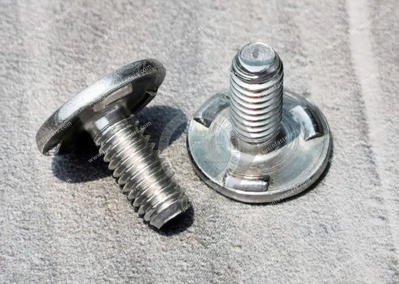
Weld studs
Flanged weld nuts
Square weld nuts
Custom weld fasteners
High-strength fastening applications
Sheet-metal assemblies
Automotive and EV applications
Electrical equipment
Industrial machinery
Custom OEM components
For fatigue-critical applications, the most useful starting point is not simply:
“What is the strongest weld nut?”
A better engineering question is:
“What fastener, material, welding process, joint geometry, preload condition, and validation method will provide the required durability for this specific load path?”
That distinction is important when developing production fasteners for demanding OEM applications.
Weld Fasteners Engineering & Selection
Weld Nuts vs. Self-Clinching Nuts
Weld Nuts vs. Blind Rivet Nuts
Weld Nut Spin Failure Analysis & Prevention
Weld Stud Push-Out & Pull-Out Failure Analysis
Sheet Metal Thickness Guidelines for Weld Fasteners
Edge Distance & Hole Clearance Rules for Weld Fasteners
Substrate Material Compatibility for Weld Fasteners
Automotive BIW Weld Fasteners
EV Battery Enclosure Weld Fasteners
Fastener Hydrogen Embrittlement Prevention
Fastener Corrosion Resistance & Salt Spray Testing
Fastener Supplier Quality Audits & Certifications
Fastener Procurement & RFQ Best Practices
A: Fatigue failure is driven by cumulative damage caused by repeated stress cycles. Even when peak loads remain below the static yield limit,
localized stress concentrations can initiate micro-cracks that progressively grow under repeated loading.
A: No. Fatigue performance depends on material, geometry, surface condition, preload, stress concentration, welding quality, parent-sheet behavior,
and the actual loading spectrum. Higher static strength does not automatically mean higher system-level fatigue life.
A: Weld nuts can be used in vibration-exposed assemblies when the fastener, weld joint, parent sheet, bolt preload, and load path are appropriately designed and validated.
The application should be evaluated as a complete joint rather than based solely on the weld-nut type.
A: Not by itself. Square, hexagonal, tab, and other anti-rotation geometries can improve assembly behavior, but fatigue performance depends on the complete structural and fastening system.
A: No. Vibration loosening involves loss of clamp force or rotational movement of the mating fastener, while fatigue involves progressive damage under repeated stress.
The two mechanisms can interact and should be investigated separately.
A: Where practical, yes. A representative production-intent joint can provide more useful information than a test of the isolated fastener because the parent sheet,
weld interface, bracket geometry, and load path can all influence the failure mode.
A: Yes, the engineering review can begin with the available application information, including drawings, parent-sheet material and thickness, welding process, load direction,
vibration profile, environmental conditions, annual volume, and required validation criteria.
A: Ideally provide the 2D drawing, 3D CAD model, material and coating requirements, parent-sheet information, welding process, cyclic load or vibration profile,
validation requirements, annual volume, packaging requirements, and quality-documentation requirements.
If your application involves cyclic loading, vibration, shock, repeated assembly loads, or fatigue-critical sheet-metal joints, send your engineering requirements to our team.
Please include:
2D engineering drawings
3D CAD models
Cyclic loading profiles
Vibration test specifications
Parent-sheet material and thickness
Welding process information
Surface-treatment requirements
Validation requirements
Annual volume forecasts
EMAIL: info@juxinfasteners.com
WEBSITE: www.juxinfasteners.com
JUXIN FASTENERS supports OEM customers in evaluating weld fastener requirements from application definition and engineering review through prototype, validation, production, and supply-chain planning.
For fatigue-critical applications, the most reliable sourcing decision comes from evaluating the fastener + weld interface + parent sheet + joint preload + load spectrum + environment + manufacturing process as one engineered system.
Precision Fastening Solutions Since 2003.
Product Packaging
Packaging Standard
At Juxin Fasteners, we apply standardized export packaging to ensure product protection, traceability, and compliance with international logistics requirements.
1. Standard Export Packaging
Unless otherwise specified, all products will be packed according to our factory standard export packaging, which includes:
Moisture-resistant inner protection
Poly bag or small box packing as required
Reinforced export cartons
Clear labeling with part number, specification, batch number, and quantity
Palletizing for sea or air shipment when necessary
Our standard packaging is designed to ensure safe transportation, efficient warehousing, and long-distance international shipping.
2. Customized Packaging Options
We also provide customized packaging solutions according to customer requirements, including but not limited to:
Private labeling
Customized barcodes
Specific carton dimensions
Retail packaging
Special pallet configuration
Customer-specific marking and identification
So that you know, customized packaging may involve additional costs and extended lead time depending on the complexity of the requirements.
3. Compliance & Quality Assurance
All packaging processes are controlled under our ISO 9001 quality management system to ensure consistency, traceability, and product integrity throughout the supply chain.
Product Pictures
Contact Us
Tel.:
+86 020 8621 0320
+86 020 3121 6067
E-mail:
Technical Support:
Navigation
SEND INQUIREY