
Call Us
+86 136 6007 9809
Call Us
+86 136 6007 9809

Aug. 16, 2026
Automotive Weld Studs for Body-in-White and Sheet Metal Assemblies
Automotive manufacturing requires fastening systems that combine reliable attachment, lightweight design, dimensional consistency, and efficient high-volume assembly.
Modern vehicle production uses a wide range of steel and aluminum components throughout the body-in-white (BIW), underbody, interior, electrical systems, and fabricated brackets.
Automotive weld studs provide permanent threaded attachment points on suitable metal components.
Depending on the stud design and welding process, they can eliminate certain through-holes, reduce loose fastener handling, and simplify subsequent assembly operations.
Common applications include wiring harness mounting, interior brackets, cable routing, heat shields, electronic module supports, body panels, and selected chassis-related components.
However, automotive weld studs should not be selected by thread diameter alone.
Their performance depends on the stud geometry, substrate material, sheet thickness, surface coating, welding process, joint loading, and production conditions.
For automotive design engineers, the priority is a fastening solution that meets dimensional, mechanical, and durability requirements.
Manufacturing engineers and production managers must also consider welding equipment, automated feeding, cycle time, process capability, and quality consistency.
Purchasing and supplier development teams need reliable technical specifications, qualified alternatives, cost visibility, and a supply arrangement aligned with OEM production schedules.
JUXIN FASTENERS supplies threaded projection weld studs, capacitor discharge weld studs, and related industrial fastening products for automotive and fabricated sheet metal applications.
Customer-specific requirements can be evaluated through drawings, material specifications, welding conditions, and planned production quantities.
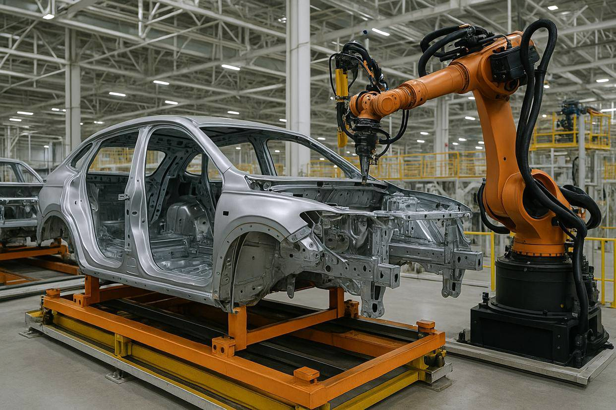
How Automotive Weld Studs Work
A weld stud is a metal fastener permanently joined to a compatible substrate through a welding process.
The stud generally provides an external thread for a mating nut, allowing another component to be attached after the stud has been installed.
In a typical automotive manufacturing sequence, studs may be welded to stamped panels or fabricated brackets before the final vehicle assembly operation.
This creates a retained attachment point without requiring an operator to hold a separate bolt during downstream assembly.
Depending on the stud design, the fastening system may offer several manufacturing benefits:
Reduced handling of loose threaded components.
Elimination of selected drilling operations.
Improved accessibility for one-sided final assembly.
Repeatable attachment locations.
Compatibility with suitable automated welding equipment.
Potential reduction in assembly operations.
Integration into existing sheet metal fabrication sequences.
These benefits are application-dependent.
For example, a surface-mounted CD weld stud may eliminate the need for a through-hole, while a through-hole projection weld stud may intentionally require a locating hole in the panel.
The correct design should be evaluated against the complete vehicle manufacturing process.
Automotive Weld Studs for Body-in-White (BIW)
Body-in-white manufacturing involves joining stamped and formed metal components into the vehicle body structure before final trim and equipment installation.
Weld studs may be integrated into suitable BIW components to provide mounting points for brackets, interior systems, electrical components, and other secondary assemblies.
Potential applications include:
Floor panel attachment points.
Body-side mounting brackets.
Interior reinforcement accessories.
Firewall and bulkhead brackets.
Underbody cable supports.
Heat shield mounting points.
Hood and trunk accessory brackets.
Equipment and electronic module supports.
The suitability of a welded stud depends on the function of the connected component and the approved vehicle design.
BIW Mounting Points and Structural Load Paths
Not every fastening point on a body structure performs the same function.
A stud securing a wiring harness clip carries very different loads from an attachment supporting a safety-critical structural component.
Engineers must distinguish between secondary mounting points and connections involved in crash performance, occupant restraint, suspension loading, or other safety-critical functions.
For safety-critical assemblies, stud geometry, material, weld performance, fatigue resistance, and validation must be established by the responsible vehicle engineering team.
A general-purpose weld stud should not be assumed suitable for a seat belt anchor, suspension attachment, or crash-load connection without application-specific engineering approval.
Stud Positioning in Stamped Panels
Automotive sheet metal components often contain formed flanges, embossments, bends, reinforcement features, and complex surfaces.
These features can affect welding access and stud positioning.
The stud location should account for:
Panel curvature and local flatness.
Welding electrode or gun access.
Distance from bends and formed edges.
Nearby spot welds and adhesive joints.
Component assembly clearance.
Thread projection and nut engagement.
Robotic positioning tolerance.
Subsequent coating and assembly operations.
A location that appears acceptable in CAD may be difficult to weld consistently if the production tooling cannot provide adequate access or support.
Early design-for-manufacturing review helps avoid late-stage fixture modifications.
Projection Weld Studs for Automotive Sheet Metal
Projection weld studs are commonly used in fabricated automotive components where a permanent male-threaded fastening point is required.
These fasteners incorporate engineered welding projections that concentrate electrical current and mechanical pressure during resistance welding.
In a typical projection welding operation, the stud and substrate are positioned between suitable electrodes. Controlled current and force generate heat at the projection interfaces, allowing the materials to join.
The resulting weld depends on the projection geometry, electrode configuration, welding schedule, and substrate characteristics.
Three-Projection Weld Studs
Three-projection weld studs use three localized welding features arranged around the stud head or designated welding surface.
The projections establish defined contact points during resistance welding.
Potential benefits include controlled weld location, compatibility with suitable fixtures, and repeatable installation when the process is correctly developed.
However, three projections do not automatically guarantee superior weld strength or eliminate the need for qualification.
The actual connection must be validated using the selected stud and production substrate.
JUXIN FASTENERS supplies Type UC3 Carbon Steel Projection Weld Studs, including designs with three projections beneath the head for suitable through-hole applications.
For automotive projects, the exact configuration should be reviewed against the panel design and required welding equipment.
Through-Hole vs. Surface-Mounted Projection Studs
Projection weld studs may use different locating and welding arrangements.
Some configurations pass through a prepared hole in the sheet before welding.
Others are designed to be positioned against the substrate surface.
This distinction affects panel preparation, fixture design, welding access, and the appearance of the finished assembly.
A through-hole configuration should not be marketed as a no-drilling solution.
Likewise, a surface-mounted configuration should not be substituted for a through-hole design without reviewing the joint geometry and approved manufacturing process.
Weld Studs for Automotive Interiors and Electrical Systems
Automotive interiors contain extensive wiring, electronic modules, brackets, trim components, insulation systems, and serviceable assemblies.
Threaded weld studs can provide attachment points for suitable interior components without requiring conventional loose bolts to be positioned during every assembly operation.
Typical applications include:
Instrument panel support accessories.
Interior mounting brackets.
Wiring harness retention.
Cable routing supports.
Carpet and insulation retainers.
HVAC-related brackets.
Electronic control module supports.
Trim and service panel attachments.
For these applications, engineers should consider the attachment load, available clearance, installation torque, vibration, and service requirements.
Weld Studs for Wiring Harness Installation
Modern vehicles incorporate increasingly complex electrical systems.
Wiring harnesses must be routed around structural components, moving assemblies, heat sources, and other vehicle systems.
Weld studs can provide fixed mounting points for clips, cable clamps, and harness support brackets.
The fastening system should be designed to maintain adequate harness retention without damaging the cable insulation or creating excessive local stress.
Important design considerations include:
Harness routing geometry.
Clip and bracket compatibility.
Stud location and projection height.
Vibration and dynamic movement.
Temperature exposure.
Electrical clearance.
Corrosion protection.
Assembly accessibility.
Service and repair requirements.
For example, a stud located too close to a sharp panel edge may complicate cable routing even when the weld itself is mechanically sound.
A successful design must account for both the fastening connection and the installed harness path.
Electrical Grounding and Bonding Attachments
Certain automotive electrical assemblies use threaded attachment points for grounding or bonding connections.
However, a welded stud does not automatically provide a validated electrical connection.
Electrical performance depends on the stud material, weld interface, surface coatings, mating hardware, contact pressure, and corrosion conditions.
Where grounding or bonding is required, the complete connection should be tested against the vehicle manufacturer's electrical specifications.
Protective coatings and paint may interfere with electrical continuity unless the joint is specifically designed to accommodate them.
Automotive Galvanized Steel and Coated Sheet Welding
Automotive body panels frequently use zinc-coated or otherwise protected steel to improve corrosion resistance.
These coatings can influence stud welding performance.
In resistance projection welding, coating characteristics affect electrical contact resistance, heat generation, electrode condition, and weld formation.
In arc-based processes, coating behavior and vaporization may affect the welding conditions.
Therefore, a welding schedule developed for bare steel should not automatically be transferred to galvanized sheet.
Key Variables for Coated Steel Stud Welding
Engineering teams should review:
Base steel grade.
Sheet thickness and thickness tolerance.
Zinc coating type and coating weight.
Surface oil or other processing residues.
Stud material and welding-end geometry.
Welding process.
Electrode condition or welding gun setup.
Welding current and duration.
Applied welding force where relevant.
Required mechanical performance.
Surface appearance and corrosion protection.
The process should be developed using representative production materials rather than relying only on nominal material descriptions.
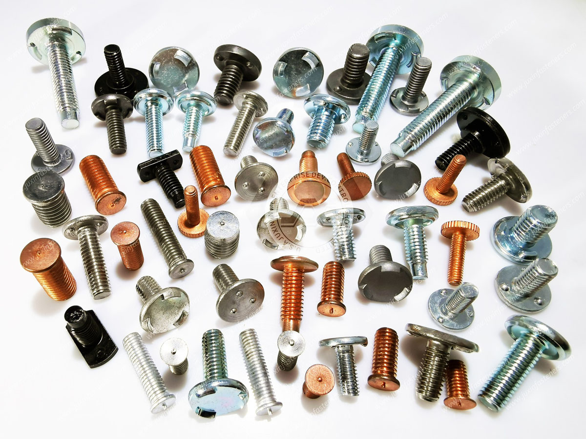
Coating Effects on Weld Formation
Coatings can change the electrical and thermal behavior of the joint.
For resistance welding, variations in contact resistance may influence where heat develops.
Electrode wear or contamination may also change the welding conditions over time.
For automated production, this creates a need to monitor both weld quality and electrode condition.
A process that produces acceptable results during initial setup may require maintenance controls to maintain consistency over a long production run.
Corrosion Protection After Welding
Welding can locally alter or damage protective coatings.
The required corrosion protection should be considered during the component design and finishing sequence.
Automotive assemblies may undergo cleaning, pretreatment, electrodeposition coating, painting, or other finishing processes.
Stud placement and geometry should allow the required coating coverage and avoid creating unnecessary moisture traps.
Corrosion performance should be validated according to the relevant OEM requirements.
Capacitor Discharge Weld Studs for Automotive Thin Sheet Metal
Capacitor discharge (CD) stud welding uses stored electrical energy released during a short welding cycle.
It can be considered for compatible thin sheet metal applications where localized heat input and controlled installation are important.
Potential automotive applications include:
Lightweight interior brackets.
Thin metal covers.
Electronic housings.
Wiring attachment points.
Suitable sheet metal panels.
Secondary equipment mounting features.
The suitability of CD welding depends on the stud configuration, base material, thickness, surface condition, and required joint performance.
Advantages and Limitations of CD Stud Welding
CD welding can provide a relatively short welding cycle and localized heat input.
This may be useful where the appearance or distortion of the opposite side of a thin panel is important.
However, low heat input does not automatically mean that the process is suitable for every high-strength steel, aluminum alloy, or safety-critical vehicle component.
The weld must be validated for the actual material combination and loading conditions.
JUXIN FASTENERS offers Aluminum Flanged CD Weld Studs for compatible applications.
For automotive OEM projects, the welding method and material combination should be confirmed before approving a product.
Projection Welding vs. CD Stud Welding vs. Arc Stud Welding
These processes are different and should not be treated as interchangeable.
| Welding Process | Typical Automotive Application | Main Engineering Consideration |
|---|---|---|
| Resistance projection welding | Threaded studs on suitable stamped panels and brackets | Projection geometry, electrode access, current and force |
| Capacitor discharge stud welding | Compatible thin metal panels and lightweight attachments | Sheet thickness, localized heat input and joint loading |
| Short-cycle or other arc stud welding | Selected automotive threaded stud applications | Stud design, base material, welding gun access and procedure |
The appropriate process depends on the fastener design and the validated production method.
A stud intended for resistance projection welding should not automatically be installed using a CD or arc welding system.
Automated Weld Stud Installation in Automotive Production
Automotive manufacturing places significant emphasis on repeatable processes and controlled cycle times.
Suitable weld studs can be integrated into automated or semi-automated installation systems.
Potential equipment configurations include:
Robotic welding cells.
Automatic stud feeding systems.
Resistance welding stations.
Stud positioning fixtures.
Automated part handling.
Weld parameter monitoring.
In-process dimensional inspection.
Production traceability systems.
Automation feasibility depends on the selected stud, feeding characteristics, part geometry, and welding equipment.
Stud Feeding and Orientation
Automatic feeding requires consistent stud geometry and reliable orientation.
A fastener that works well in manual installation may require additional evaluation before it can be used in an automated feeder.
Head dimensions, thread length, projection geometry, and surface finish may affect feeding behavior.
For production planning, fastener geometry should be reviewed together with the feeding system rather than treated as an isolated purchasing specification.
Positioning Accuracy and Fixture Design
The required stud position is determined by the downstream assembly.
A stud may have an acceptable weld but still cause assembly problems if it is incorrectly positioned.
Fixture design should account for:
Panel dimensional variation.
Part locating references.
Robot or equipment repeatability.
Electrode or welding gun alignment.
Stud perpendicularity.
Welding-related movement.
Finished thread projection.
The tolerance stack-up should include both the stamped component and the installed stud.
This is particularly important when multiple studs must align with a rigid mating bracket.
Production Cycle Time and Throughput
Stud welding can reduce certain assembly operations, but total throughput depends on more than the welding cycle itself.
The complete production sequence may include feeding, positioning, welding, cooling or hold time, inspection, and part transfer.
A faster nominal welding cycle does not necessarily produce a faster production line.
Production managers should evaluate the actual station cycle time, equipment availability, reject rate, maintenance requirements, and downstream assembly effects.
Process Monitoring and Preventive Maintenance
Automated welding equipment may monitor process variables such as current, voltage, time, force, or other signals depending on the welding technology.
These measurements can help detect process variation.
However, monitoring a welding parameter does not automatically prove that every completed joint meets its mechanical requirements.
A suitable control plan should combine process monitoring with appropriate validation, inspection, and maintenance.
Automotive Weld Stud Material Selection
Stud material selection should account for weldability, mechanical loading, substrate compatibility, corrosion exposure, and assembly requirements.
Carbon Steel Weld Studs
Carbon steel weld studs are commonly considered for compatible steel sheet metal assemblies.
The selected material must provide the required mechanical properties while remaining suitable for the intended welding process.
A higher nominal strength grade does not automatically provide better weldability.
Material selection should consider the welding-end design and the actual steel composition.
Stainless Steel Weld Studs
Stainless steel studs may be suitable for applications requiring corrosion resistance.
However, stainless steel grades differ in weldability, mechanical properties, and corrosion behavior.
The selected stud must be compatible with the substrate and welding process.
Where stainless steel is combined with carbon steel or other metals, the complete corrosion environment should be evaluated.
Aluminum Weld Studs
Aluminum weld studs may be considered for compatible aluminum components.
However, aluminum welding involves different thermal and metallurgical conditions from conventional steel welding.
The process should be qualified for the specific alloy and component.
Aluminum studs should not be assumed suitable for direct welding to steel merely because both materials are used in the same vehicle.
High-Strength Steel and Mixed-Material Assemblies
Modern automotive structures may use high-strength steels, advanced high-strength steels, aluminum alloys, and mixed-material assemblies.
These materials can create additional fastening challenges.
Welding may affect local material properties, particularly in heat-sensitive steels.
Mixed-metal joining may require a different attachment technology or an engineered transition component.
Where direct stud welding is unsuitable, engineers may consider other fastening methods based on the assembly requirements.
Metric and Inch Thread Specifications
Automotive weld studs may be supplied with ISO metric or Unified inch-series threads according to the approved product specification.
Relevant thread standards include ISO 261 and ISO 965 for metric threads and ASME B1.1 for Unified threads.
Metric and UNC/UNF threads are not directly interchangeable.
For example, M6 × 1.0 and 1/4-20 UNC have different thread geometry and pitch.
A similar nominal diameter does not establish compatibility with the mating nut.
Thread substitutions should be reviewed against the approved engineering drawing, tolerance requirements, and assembly design.
Mechanical Performance and Joint Reliability
Automotive weld stud performance should be evaluated as part of the complete fastening system.
The relevant load cases depend on the application.
For a wiring harness clip, the main concerns may include retention, vibration, and serviceability.
For a heavier equipment bracket, the design may involve tension, shear, bending, fatigue, and joint preload.
Tensile and Pull-Off Resistance
The installed stud must resist the required axial loading.
The failure mode may involve the stud, weld, or surrounding sheet metal.
A high-strength stud does not guarantee that a thin substrate can support the same load.
The connection must be validated using representative production materials.
Torque Resistance During Assembly
Threaded weld studs experience torsional loading when mating nuts are tightened or removed.
Insufficient weld resistance may cause the stud to rotate or fail during assembly.
The specified nut tightening torque must be compatible with the stud, weld, substrate, and complete joint.
Torque testing should follow the approved test method and acceptance criteria.
Vibration and Fatigue
Vehicle components experience vibration and repeated loading throughout their service life.
A permanent weld does not automatically prevent the mating nut from loosening.
Where necessary, the joint may require an appropriate locking nut or another validated anti-loosening method.
Fatigue performance must also be evaluated for applications subjected to significant cyclic loading.
Sheet Metal Deformation and Local Strength
Thin automotive panels may deform before the stud or weld reaches its nominal strength.
Local panel stiffness, reinforcement geometry, and loading direction are therefore important.
Designers should evaluate whether the surrounding sheet metal can transfer the intended loads without unacceptable distortion.
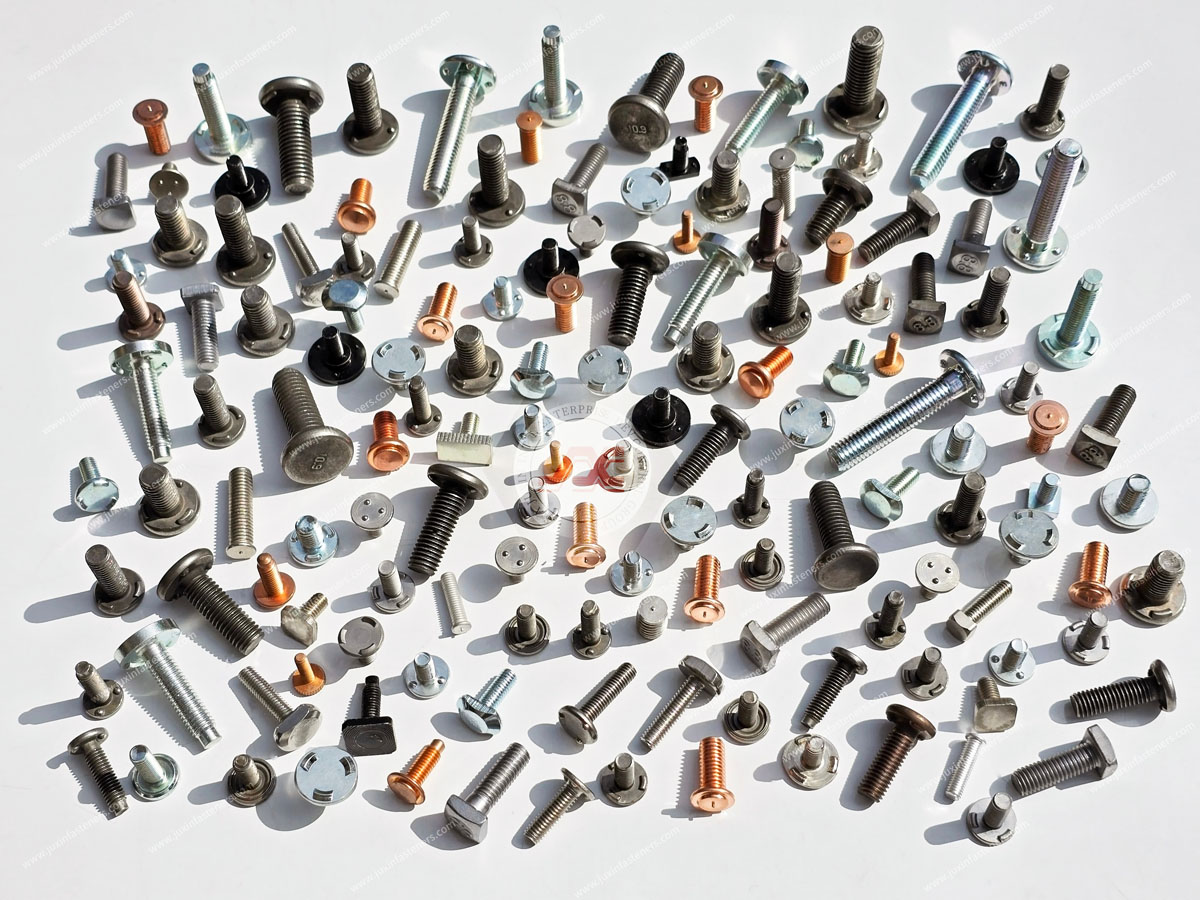
Automotive Weld Stud Quality Control and Production Validation
Automotive OEMs and Tier suppliers commonly require controlled production processes and documented product conformity.
The exact quality requirements depend on the customer, application, and contractual specifications.
Dimensional and Visual Inspection
Typical checks may include:
Thread diameter and pitch.
Stud length and head dimensions.
Projection geometry.
Installed stud position.
Perpendicularity.
Thread condition.
Weld appearance.
Local sheet deformation.
These checks help identify dimensional and installation defects.
However, visual appearance alone does not establish mechanical joint strength.
Mechanical Weld Testing
Depending on the application and approved test procedure, validation may involve pull testing, torque testing, destructive examination, or other appropriate methods.
The correct test depends on the stud design and expected loading.
Acceptance criteria should be defined by the customer or approved engineering specification.
It is not appropriate to assign a universal pull-off or torque value to all automotive weld studs of the same nominal thread size.
Production Part Approval Process (PPAP)
Automotive customers may require PPAP submissions or other production approval documentation.
The applicable submission level, content, and approval process must be agreed with the customer.
Possible requirements may include dimensional results, material documentation, process flow information, control plans, and other specified records.
PPAP capability should be confirmed for the particular project rather than assumed from a general product description.
Traceability and Lot Control
Production traceability may be required to connect delivered fasteners with material lots, manufacturing records, inspection results, and customer shipments.
The required level of traceability depends on the customer's quality agreement.
For high-volume automotive programs, consistent part identification and packaging can help reduce line-side handling errors.
Common Automotive Weld Stud Failures and Prevention
Incomplete Weld Formation
Incorrect welding parameters, unsuitable surface conditions, or equipment problems can produce insufficient weld formation.
Prevention: Validate the welding schedule using actual production materials and maintain process controls.
Stud Misalignment
Incorrect positioning may interfere with mating brackets or prevent automated nut installation.
Prevention: Control part locating, fixture condition, and installed stud position.
Weld Spatter and Thread Damage
Excessive spatter or improper handling can damage threads and complicate downstream assembly.
Prevention: Optimize the welding process and protect critical thread features where necessary.
Coating-Related Weld Variation
Differences in galvanized coating or surface contamination may change weld behavior.
Prevention: Include actual coating conditions in process development and monitor relevant production variables.
Local Sheet Deformation
Excessive heat or unsuitable loading may distort thin panels.
Prevention: Match stud geometry and welding process to the substrate thickness and material.
Stud Rotation During Nut Tightening
An insufficient weld may fail when the mating nut is tightened.
Prevention: Validate torsional resistance against the assembly requirements.
Corrosion at the Weld Interface
Welding may damage protective coatings and expose local metal surfaces.
Prevention: Coordinate welding and finishing operations and validate corrosion protection.
Incorrect Thread Substitution
Metric and Unified thread systems may be confused during global sourcing.
Prevention: Maintain exact thread specifications and verify the mating components.
Automotive Weld Stud Procurement and OEM Supplier Development
Automotive purchasing decisions involve technical performance, manufacturing feasibility, quality assurance, commercial terms, and long-term supply planning.
A suitable supplier must understand the specified product rather than quoting only a nominal thread size.
Drawing and Application Review
A complete automotive weld stud RFQ should identify:
Product drawing and part number.
Stud type and welding process.
Thread specification.
Stud material and mechanical requirements.
Head and projection geometry.
Substrate material and thickness.
Surface coating.
Installation and assembly conditions.
Required mechanical performance.
Inspection and documentation requirements.
These details allow the supplier to evaluate whether the proposed fastener is compatible with the intended application.
Alternative Fastener Qualification
When developing an alternative supplier, buyers should compare more than the nominal thread diameter.
Potential differences include:
Head geometry.
Projection configuration.
Welding-end design.
Material composition.
Thread tolerance.
Overall length.
Surface finish.
Welding equipment compatibility.
Mechanical performance.
An alternative fastener should be approved through the customer's required engineering and quality process.
MOQ, Lead Time and Annual Demand
MOQ and lead time depend on the selected product, material, dimensions, manufacturing requirements, and order volume.
For recurring automotive production, buyers should provide estimated annual usage, initial order quantities, forecast information, and delivery expectations.
This allows the supplier to evaluate commercial feasibility and production planning requirements.
Total Installed Cost
The lowest fastener price does not necessarily represent the lowest assembly cost.
A broader cost comparison may include:
Fastener unit price.
Welding cycle and handling time.
Equipment and tooling.
Feeding reliability.
Inspection and testing.
Scrap and rework.
Packaging and logistics.
Production interruptions.
Supplier delivery consistency.
For automotive manufacturing, stable installation performance can be particularly important because a fastener defect may interrupt downstream assembly operations.
Engineering and Procurement Checklist for Automotive Weld Studs
| Evaluation Area | Required Information |
|---|---|
| Application | BIW, interior, electrical, bracket or other vehicle assembly |
| Stud type | Projection weld, CD weld or other approved configuration |
| Thread | Metric or Unified size, pitch and tolerance |
| Geometry | Stud length, head dimensions and welding-end design |
| Material | Stud grade and substrate compatibility |
| Sheet metal | Steel or aluminum grade, thickness and coating |
| Welding | Equipment, access, parameters and validation |
| Mechanical performance | Pull-off, torque, vibration or other specified requirements |
| Quality | Inspection, PPAP and customer-specific documentation |
| Production | Automation, feeding, cycle time and process controls |
| Procurement | Quantity, forecast, MOQ, lead time and packaging |
This checklist helps engineering, manufacturing, and purchasing teams establish a consistent technical specification before approving a weld stud supplier.
Automotive Weld Stud Supplier and OEM Solutions – JUXIN FASTENERS
JUXIN FASTENERS supplies threaded weld studs and related fastening products for automotive sheet metal and industrial OEM applications.
Our relevant product portfolio includes:
Three-projection weld studs.
Threaded projection weld studs.
Capacitor discharge weld studs.
Suitable carbon steel and stainless steel configurations.
Aluminum CD weld stud options.
Metric and Unified thread specifications.
Customer-specified stud dimensions and geometries.
Welded fastening products for fabricated brackets and panels.
For related product information, see:
Type UC3 Carbon Steel Projection Weld Studs
Aluminum Flanged CD Weld Studs
Projection Weld Studs: Engineering Mechanics, DFM and OEM Sourcing Guide
JUXIN FASTENERS can review customer drawings, material specifications, welding requirements, and expected production quantities to evaluate suitable product options.
Any automotive-specific validation, documentation, material requirement, or production approval must be confirmed for the individual project.
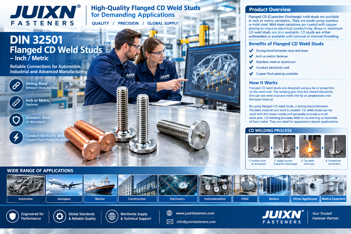
Request an Automotive Weld Stud RFQ
Are you sourcing weld studs for body-in-white manufacturing, galvanized steel panels, wiring harness mounting, interior brackets, electronic equipment, or automated sheet metal assembly?
JUXIN FASTENERS welcomes inquiries from automotive OEMs, Tier suppliers, design engineers, manufacturing engineers, production teams, purchasing departments, and supplier development professionals.
For an accurate technical review and quotation, please provide:
Available 2D drawings or 3D CAD models.
Required stud type and thread specification.
Stud material and mechanical requirements.
Substrate material, thickness and coating.
Welding process and production equipment details.
Installation location and assembly requirements.
Required pull, torque or other validation criteria.
Customer-specific quality and documentation requirements.
Initial order quantity and estimated annual demand.
Target production and delivery schedule.
If you are evaluating an alternative to an existing automotive weld stud, please include the original drawing and specification.
Our objective is to help customers identify appropriate welded fastening solutions that support reliable assembly, efficient production, and consistent OEM procurement.
JUXIN FASTENERS
Website: https://www.juxinfasteners.com
Email: info@juxinfasteners.com
Send your technical drawings and RFQ to discuss your automotive welded stud requirements.
Contact Us
Tel.:
+86 020 8621 0320
+86 020 3121 6067
E-mail:
Technical Support:
Navigation
SEND INQUIREY



