
Call Us
+86 136 6007 9809
Call Us
+86 136 6007 9809

Aug. 16, 2026
Welded Studs for Power Generation and Energy Infrastructure
Power generation and energy infrastructure depend on reliable fastening systems for electrical equipment, structural steel assemblies, industrial enclosures, pipe supports, and fabricated machinery components.
These installations may operate under vibration, elevated temperatures, corrosive conditions, and demanding maintenance schedules.
Welded studs provide permanent attachment points on compatible metal substrates. Depending on the stud design and welding process, they can reduce loose hardware handling,
eliminate selected through-holes, and simplify the assembly of equipment brackets, electrical cabinets, cable supports, and other industrial components.
However, welded studs used in energy facilities perform different functions.
A threaded weld stud securing a transformer enclosure accessory is not equivalent to a structural attachment carrying heavy machinery loads or a welded component forming part of a pressure boundary.
The correct fastener must be selected according to its load path, base material, installation process, operating environment, and applicable engineering requirements.
For mechanical and structural engineers, the priority is joint integrity and suitable mechanical performance.
Manufacturing engineers and production managers focus on repeatable installation, welding access, process control, and assembly cost.
Procurement and supplier development teams require accurate specifications, qualified product alternatives, documentation, and dependable supply planning.
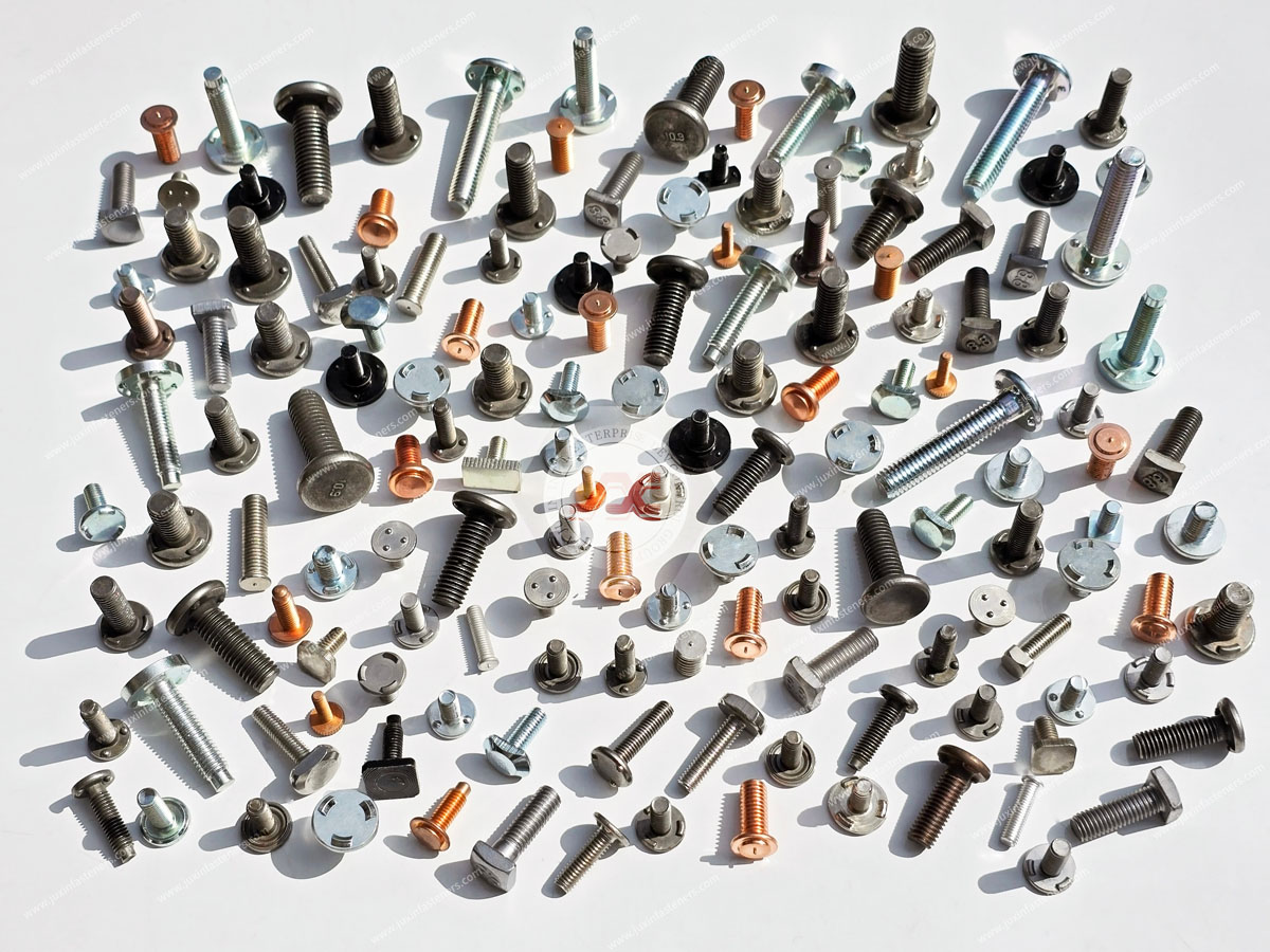
JUXIN FASTENERS supplies industrial threaded weld studs, projection weld studs, capacitor discharge weld studs,
and related fastening products for compatible fabricated metal and OEM equipment applications. Customer-specific energy equipment requirements can be reviewed against drawings, materials, welding conditions, and expected order quantities.
Where Are Welded Studs Used in Power and Energy Equipment?
Welded studs may be considered for suitable secondary attachments and fabricated components in power generation and energy infrastructure.
Typical applications include:
Electrical equipment enclosures.
Transformer housing accessories.
Power distribution cabinets.
Cable tray and conduit brackets.
Instrumentation mounting panels.
Industrial equipment covers.
Non-pressure pipe support brackets.
Fabricated steel mounting plates.
Auxiliary equipment assemblies.
Selected structural steel attachments subject to engineering approval.
The required fastener type depends on the component's function.
For example, a threaded stud used to mount a removable electrical panel may primarily experience assembly torque and modest service loads.
A stud supporting a vibrating pump accessory may require additional consideration of fatigue, bending, and threaded joint loosening.
A stud attached to a pressure-containing pipe or vessel requires a separate level of engineering review and must not be treated as a routine industrial mounting application.
Welded Studs for Power Plant Steel Structures
Power plants contain extensive structural steel supporting equipment, platforms, cable systems, and industrial services.
Suitable welded studs may provide attachment points for secondary brackets and fabricated accessories where welding is permitted by the approved structural design.
Potential applications include:
Cable support brackets.
Instrument mounting assemblies.
Auxiliary equipment panels.
Access cover attachments.
Non-primary support components.
Fabricated steel brackets.
Structural Load Paths and Attachment Classification
The first design decision is whether the welded attachment performs a primary structural function or supports a secondary component.
A stud used to secure a lightweight instrument panel is fundamentally different from a connection supporting heavy equipment or carrying significant structural forces.
For structurally significant attachments, the responsible engineer must evaluate the stud, weld, substrate, and connected component as a complete system.
Relevant failure modes may include stud fracture, weld failure, local base-metal yielding, tearing, fatigue, and corrosion.
The nominal tensile strength of the stud alone does not establish the capacity of the installed connection.
Welding Near Existing Structural Details
Stud location should account for existing welds, bolt holes, structural stiffeners, edges, and high-stress regions.
Additional welded attachments can create local stress concentrations or affect fatigue-sensitive details.
For existing power plant structures, modifications should be reviewed against the original design and applicable facility requirements.
Stud welding should not be performed on critical structural members without the necessary engineering approval.
Thermal Movement and Equipment Supports
Power generation equipment may experience substantial temperature variation during startup, operation, and shutdown.
Thermal expansion can impose additional forces on brackets and supporting structures.
A rigidly attached stud may be suitable for one component but inappropriate where the assembly must accommodate movement.
Engineers should determine whether the connection requires sliding, flexibility, thermal clearance, or another engineered support arrangement.

Threaded Weld Studs for Transformer and Electrical Equipment Enclosures
Transformer housings, electrical cabinets, switchgear enclosures, and power distribution equipment often require retained threaded attachment points.
Welded studs may be used on suitable fabricated panels to mount secondary components without loose bolts passing through the enclosure wall.
Potential applications include:
Transformer enclosure accessories.
Electrical cabinet brackets.
Cable management components.
Equipment mounting panels.
Internal support brackets.
Removable covers.
Instrumentation accessories.
Control system hardware.
Enclosure Integrity and Surface Appearance
Surface-mounted weld studs can reduce the need for certain through-holes.
This may be useful where an enclosure requires controlled ingress protection or a clean exterior appearance.
However, a welded stud does not automatically establish an IP-rated, watertight, oil-tight, or hermetically sealed connection.
The complete enclosure design, including welded joints, coatings, seals, and penetrations, must be validated against the specified environmental requirements.
For thin enclosure panels, engineers should also evaluate local distortion and the appearance of the opposite surface after welding.
Electrical Clearance and Insulation Coordination
Electrical equipment may require defined clearances and creepage distances between energized components and conductive structures.
Adding a metal stud can affect the available clearance or introduce an unintended conductive feature.
The stud location should be reviewed against the equipment's electrical design.
The fastener must not interfere with insulation systems, moving mechanisms, cable routing, or service access.
Grounding and Protective Bonding
Welded studs are sometimes considered for grounding or protective bonding attachments.
However, welding a stud to a metal enclosure does not automatically create a validated protective earth connection.
Electrical continuity depends on the weld, substrate, surface coatings, mating hardware, contact pressure, and long-term corrosion behavior.
Where the stud forms part of a protective bonding system, the complete connection must meet the applicable equipment requirements and be verified using the specified test method.
For relevant low-voltage equipment, IEC 61439 and IEC 62271 series requirements may be applicable depending on the product type and scope.
These are equipment standards, not general certifications for the weld stud itself.
Transformer Tank and Oil-Containing Equipment Restrictions
Transformer tanks and some electrical equipment housings contain insulating oil or other fluids.
Welding attachments to these components requires particular caution.
A general-purpose CD or projection weld stud must not be assumed suitable for a pressure-retaining, oil-tight, or otherwise critical tank wall.
Where a welded attachment is proposed on a transformer tank, the equipment manufacturer must evaluate material thickness, weld procedure, leakage risk, internal condition, and applicable product requirements.
Any sealing performance must be demonstrated for the complete assembly.
Projection Weld Studs for Electrical Cabinet Manufacturing
Resistance projection weld studs can provide threaded attachment points in suitable sheet metal fabrication.
These fasteners incorporate engineered projections that concentrate electrical current and electrode force at defined welding locations.
The process is commonly associated with factory-based manufacturing, where parts can be positioned and supported using appropriate resistance welding equipment.
Three-Projection Weld Studs
Three-projection weld studs use localized welding features arranged around the head.
The projections are intended to control the initial contact points and welding heat distribution.
JUXIN FASTENERS supplies Type UC3 Carbon Steel Projection Weld Studs for suitable through-hole applications.
For this configuration, the stud passes through a prepared hole before welding.
This is an important distinction: a through-hole projection weld stud does not eliminate the panel hole.
Its potential manufacturing advantages must be evaluated against the actual fabrication process.
Stud Positioning and Assembly Clearance
Electrical cabinets frequently contain closely spaced components, DIN rails, wiring channels, and removable covers.
The stud location should account for:
Internal component clearance.
Welding electrode access.
Panel thickness and flatness.
Nearby bends and formed edges.
Thread projection.
Mating bracket alignment.
Coating thickness.
Maintenance accessibility.
A stud may have an acceptable weld but still cause assembly interference if its position is incorrect.
Design-for-manufacturing review should therefore include both welding feasibility and downstream assembly.
Capacitor Discharge Weld Studs for Thin Equipment Panels
Capacitor discharge (CD) stud welding uses stored electrical energy released during a short welding cycle.
It may be suitable for compatible relatively thin metal panels where localized heat input is important.
Potential applications include:
Electrical enclosure panels.
Control cabinet accessories.
Instrument housings.
Lightweight brackets.
Equipment covers.
Selected cable support attachments.
CD stud welding should not be assumed appropriate for heavy structural attachments or pressure-containing equipment.
The selected stud, substrate, and welding procedure must be validated for the required performance.
JUXIN FASTENERS offers Flanged CD Weld Studs in Metric and Inch Configurations and [Non-Flanged CD Weld Studs](https://www.juxinfasten ers.com/cd-weld-fasteners-inch-metric/non-flanged-cd-weld-studs.html).
A non-flanged design may be useful where the flange of a conventional stud would interfere with the mating component.
However, flange selection affects geometry and welding behavior and must be verified for the application.
Welded Studs for Pipe Supports and Energy Facility Piping Systems
Power plants, refineries, gas processing facilities, and other energy installations contain extensive piping networks.
These systems require engineered supports that accommodate pipe weight, operating loads, thermal movement, vibration, and maintenance.
Welded studs may be considered for suitable secondary brackets or fabricated support components.
Potential applications include:
Instrumentation brackets.
Cable supports associated with piping systems.
Non-pressure auxiliary mounting plates.
Pipe support accessories.
Fabricated steel support frames.
Equipment identification or protective accessories.
Pressure Boundary vs. Non-Pressure Support Attachments
A critical distinction is whether the proposed stud is attached to a pressure-containing component.
Welding a stud to a separate structural support frame is not equivalent to welding directly onto a pressurized pipe, pressure vessel, boiler drum, or other pressure boundary.
Pressure-boundary attachments may be subject to design, material, welding, inspection, and regulatory requirements.
Depending on the installation, relevant requirements may include ASME B31.1 for power piping, ASME B31.3 for process piping, or applicable ASME Boiler and Pressure Vessel Code provisions.
The exact governing code must be established by the responsible engineer.
General-purpose industrial weld studs should not be proposed for direct pressure-boundary attachment without the required engineering approval and qualified procedure.
Thermal Expansion and Pipe Support Movement
Piping systems can expand and contract significantly as operating temperatures change.
Support arrangements may include fixed points, guides, sliding supports, springs, or other engineered components.
A rigid welded attachment should not be introduced without evaluating the required pipe movement.
Otherwise, the connection may create unintended loads or restrict thermal expansion.
Vibration and Fatigue in Pipe Support Systems
Pumps, compressors, turbines, and fluid flow can generate vibration.
Welded stud attachments subjected to repeated loading may require fatigue evaluation.
The mating threaded joint may also require a validated locking method.
A permanent weld does not prevent a nut from loosening under vibration.
Weld Studs for Renewable Energy and Industrial Power Equipment
Energy infrastructure includes conventional power plants as well as wind, solar, energy storage, and electrical distribution equipment.
These applications can require different fastening solutions.
Wind Energy Equipment
Wind turbine assemblies experience vibration, cyclic loading, weather exposure, and maintenance constraints.
Suitable weld studs may be considered for secondary enclosure components, cable supports, or equipment accessories.
They should not be assumed suitable for primary turbine structural connections without specific engineering qualification.
Solar Power and Inverter Enclosures
Solar inverters, combiner boxes, and related electrical equipment may use sheet metal enclosures and internal mounting brackets.
Projection weld studs or CD weld studs may be appropriate for selected fabricated components.
The enclosure design must account for environmental exposure, electrical clearance, grounding, and corrosion protection.
Battery Energy Storage Equipment
Battery energy storage systems contain electrical enclosures, cable management hardware, thermal management equipment, and fabricated support structures.
Weld studs may be considered for compatible secondary attachments.
However, fastening arrangements must not interfere with electrical insulation, thermal management, fire safety systems, or equipment-specific requirements.
The complete assembly should be evaluated under the relevant product and installation specifications.
Choosing the Correct Stud Welding Process
Power and energy equipment includes thin fabricated panels, medium-thickness brackets, and heavy structural steel.
Different welding processes are suitable for different applications.
Resistance Projection Welding
Resistance projection welding uses controlled electrical current and force to create welds at engineered projection features.
It is generally considered for compatible factory-fabricated metal components.
Important variables include projection geometry, electrode access, substrate material, welding current, force, and hold time.
Capacitor Discharge Stud Welding
CD stud welding is commonly considered for compatible thin sheet metal attachments.
Its relatively localized heat input may help limit distortion in suitable applications.
However, the process must be qualified for the actual material, thickness, and loading.
Drawn-Arc Stud Welding
Drawn-arc stud welding may be relevant to larger studs and suitable heavier steel applications.
It requires an appropriate stud design, welding procedure, equipment, and inspection program.
Structural suitability must be established by the responsible engineer.
Process Comparison
| Welding Process | Typical Application | Main Engineering Consideration |
|---|---|---|
| Resistance projection welding | Factory-fabricated brackets and electrical enclosure components | Projection geometry, electrode access and process control |
| Capacitor discharge welding | Compatible thin metal panels and lightweight attachments | Substrate thickness, heat input and weld performance |
| Drawn-arc stud welding | Suitable larger stud and steel attachment applications | Weld procedure, base material and structural requirements |
These processes are not directly interchangeable.
A fastener designed for one process should not be substituted into another without technical verification.
Engineering Selection: Material, Thickness and Weldability
The correct weld stud must be compatible with the base material and the selected welding process.
Carbon Steel Weld Studs
Carbon steel studs may be suitable for compatible steel equipment components.
Material selection should consider mechanical properties, weldability, and corrosion protection.
A higher nominal strength grade does not automatically improve welding performance.
Stainless Steel Weld Studs
Stainless steel may be selected for certain corrosive environments or equipment applications.
However, stainless steel grades differ in weldability and corrosion resistance.
The selected material must be compatible with the substrate and service conditions.
JUXIN FASTENERS supplies Stainless Steel Flanged CD Weld Studs for suitable applications.
Aluminum Weld Studs
Aluminum weld studs may be considered for compatible aluminum enclosures or fabricated components.
The welding process must be appropriate for the selected alloy and material thickness.
Direct welding of dissimilar metals should not be assumed feasible without a validated joining method.
Sheet Thickness and Local Strength
Thin sheet metal may deform or fail locally before the stud reaches its nominal mechanical strength.
The installed connection must be evaluated for the actual loading direction and substrate geometry.
For heavier steel, weldability and the required welding procedure may become more significant.
There is no universal minimum substrate thickness suitable for all welded stud configurations.
Thread Specifications: Metric and Unified Inch Systems
Threaded weld studs may use ISO metric or Unified inch-series threads.
ISO 261 and ISO 965 are relevant to metric thread dimensions and tolerances, while ASME B1.1 addresses Unified inch threads.
Metric and UNC/UNF threads are not interchangeable.
For example, M6 × 1.0 and 1/4-20 UNC have different thread geometry and pitch.
A dimensional similarity does not establish mating compatibility.
Any proposed alternative thread specification must be reviewed against the approved drawing and mating components.
Mechanical Reliability Under Energy Equipment Operating Conditions
Energy equipment may operate under high temperature, vibration, corrosive atmospheres, and long service intervals.
Stud selection must consider the actual service conditions rather than relying only on nominal dimensions.
Tension, Shear and Bending
A threaded weld stud may experience axial tension, transverse shear, bending, or combined loading.
The complete connection includes the stud, weld, substrate, mating nut, and attached component.
The weakest element may govern the joint's performance.
Temperature and Thermal Cycling
Temperature changes can affect material properties, thermal expansion, joint preload, and fatigue behavior.
High-temperature applications require suitable material and joint design.
A conventional industrial weld stud should not automatically be used in high-temperature turbine or boiler environments.
Vibration and Threaded Joint Loosening
Vibration may cause loosening of the mating nut even when the stud remains securely welded.
Where required, an appropriate locking method should be selected and validated.
Corrosion and Environmental Exposure
Outdoor substations, coastal energy facilities, chemical processing plants, and industrial power equipment may experience different corrosion conditions.
Material and coating selection should reflect the actual environment.
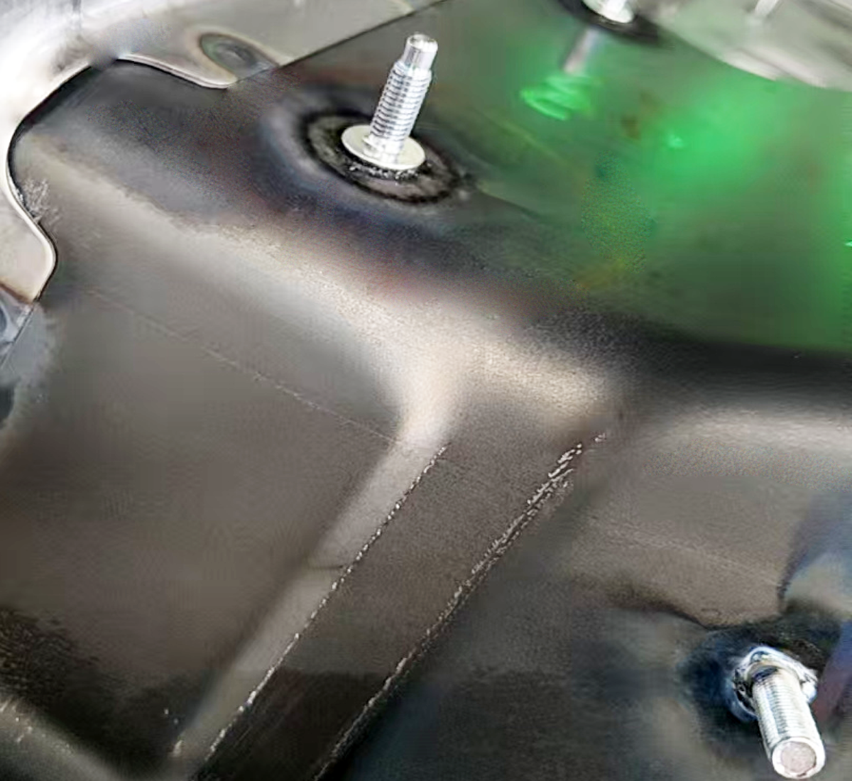
Welding may damage protective coatings, making post-weld corrosion protection an important part of the manufacturing sequence.
Manufacturing Efficiency and Production-Line Integration
Welded studs can simplify production when integrated into a suitable fabrication process.
For electrical cabinets, transformer accessories, and fabricated equipment panels, the complete manufacturing sequence may include cutting, punching, bending, welding, coating, assembly, and inspection.
Welding Before or After Coating
Welding is often performed before final protective finishing.
However, the appropriate sequence depends on the component design and coating requirements.
Welding through coatings may affect weld formation and should only be performed under an approved process.
Where welding damages protective coatings, restoration may be necessary.
Automated Stud Feeding and Positioning
Suitable stud designs may be used with automated feeding or positioning systems.
Automation feasibility depends on stud geometry, equipment, part access, and production volume.
Production managers should evaluate the complete station cycle time rather than only the nominal welding duration.
Fixture Design and Dimensional Control
A stud may have an acceptable weld but still create assembly problems if it is misaligned.
Fixtures should control the position of the component and the installed stud.
The tolerance stack-up should include the fabricated panel, stud location, thread projection, and mating assembly.
Total Installed Cost
The total cost of a welded fastening solution may include:
Fastener unit price.
Welding equipment.
Tooling and fixtures.
Installation labor.
Inspection and testing.
Surface preparation.
Coating restoration.
Scrap and rework.
Packaging and logistics.
A lower fastener price does not necessarily produce a lower total assembly cost.
Quality Control for Power and Energy Weld Studs
Quality requirements depend on the application and contractual specification.
Electrical enclosure attachments, structural steel connections, and pressure-boundary attachments may require substantially different validation programs.
Incoming Stud Inspection
Checks may include:
Stud dimensions.
Thread specification.
Material identification.
Welding-end geometry.
Surface condition.
Required documentation.
Lot identification.
Visual and Dimensional Inspection
Visual inspection may identify incorrect positioning, thread damage, and visible welding defects.
Dimensional inspection may confirm stud location, alignment, and projection.
However, visual inspection alone does not establish the required mechanical strength.
Pull and Torque Testing
Depending on the application, pull or torque testing may be relevant.
The test method and acceptance criteria must be defined for the actual joint.
A universal torque or pull-off value should not be assigned to all studs with the same thread size.
Welding Procedure Qualification
For relevant arc stud welding applications, EN ISO 14555 may apply where specified.
Structural steel welding may be governed by AWS D1.1/D1.1M or other project requirements.
Pressure-containing equipment and piping may require additional code-specific welding qualification and inspection.
The applicable standard must be established for the exact project.
Traceability and Documentation
Depending on the customer, documentation may include material certificates, dimensional reports, inspection records, or lot traceability.
Any special qualification, approval, or certification requirement should be agreed before order placement.
Common Welded Stud Failures and Prevention
Incomplete Weld Formation
Incorrect welding parameters or unsuitable surface conditions can cause insufficient weld formation.
Prevention: Validate the welding process using representative materials and equipment.
Stud Misalignment
Incorrect positioning can interfere with equipment assembly.
Prevention: Use suitable fixtures and inspect installed geometry.
Local Sheet Deformation
Excessive heat input or unsuitable stud geometry can damage thin panels.
Prevention: Match the welding process to the substrate material and thickness.
Thread Damage
Weld spatter or poor handling may damage external threads.
Prevention: Control the welding process and protect critical thread features.
Stud Rotation During Assembly
Insufficient weld resistance may cause the stud to rotate when the mating nut is tightened.
Prevention: Validate torsional resistance against the assembly requirements.
Fatigue Cracking
Repeated loading may damage the stud or welded connection.
Prevention: Evaluate fatigue where cyclic loading is significant.
Corrosion at the Weld Interface
Welding can damage protective coatings and expose local metal surfaces.
Prevention: Coordinate welding and corrosion protection.
Unapproved Pressure-Boundary Attachment
Welding directly onto a pressure-containing component without engineering approval may compromise equipment integrity.
Prevention: Follow the applicable pressure equipment design, welding, and inspection requirements.
Energy Equipment Weld Stud Procurement and Supplier Development
Power and energy equipment procurement often involves multiple technical and commercial stakeholders.
Engineers define performance and compatibility.
Manufacturing teams establish installation feasibility and quality controls.
Purchasing and supply-chain teams evaluate supplier capability, cost, documentation, and delivery planning.
Technical Drawing and Application Review
A complete weld stud RFQ should identify:
Product drawing and dimensions.
Stud type and welding process.
Thread specification.
Material and mechanical requirements.
Base material and thickness.
Surface coating.
Intended application.
Structural or pressure-boundary significance.
Required testing and documentation.
Order quantity and delivery schedule.
Alternative Fastener Evaluation
A proposed alternative should not be approved solely because it has the same nominal thread size.
Differences in welding-end geometry, head dimensions, material, thread tolerance, and welding process can affect performance.
The alternative should be reviewed against the approved engineering specification.
MOQ, Lead Time and Recurring Supply
MOQ and lead time depend on the product configuration, material, manufacturing requirements, and quantity.
For recurring OEM programs, buyers should provide estimated annual demand, initial order quantities, and delivery expectations.
This helps suppliers evaluate production planning and commercial feasibility.
Quality Documentation and Supplier Qualification
Customers may require specific material records, inspection reports, process validation, or other agreed documentation.
The requirements should be confirmed for each project.
A general supplier product listing should not be treated as evidence of compliance with all energy-industry regulations.
Engineering and Procurement Checklist for Energy Weld Studs
| Evaluation Area | Required Information |
|---|---|
| Application | Electrical enclosure, equipment bracket, structural support or pipe accessory |
| Connection function | Secondary attachment, structural connection or pressure-boundary-related |
| Stud geometry | Diameter, length, head and welding-end configuration |
| Thread | Metric or Unified size, pitch and tolerance |
| Material | Stud grade and substrate compatibility |
| Base metal | Grade, thickness and surface condition |
| Welding | Process, access and qualification requirements |
| Operating environment | Temperature, vibration and corrosion |
| Electrical requirements | Clearance, bonding and enclosure integrity where relevant |
| Quality | Inspection, testing and documentation |
| Procurement | Quantity, MOQ, lead time and delivery schedule |
This checklist helps reduce quotation ambiguity and supports more effective engineering and supplier development decisions.
Weld Stud Supply and OEM Engineering Support – JUXIN FASTENERS
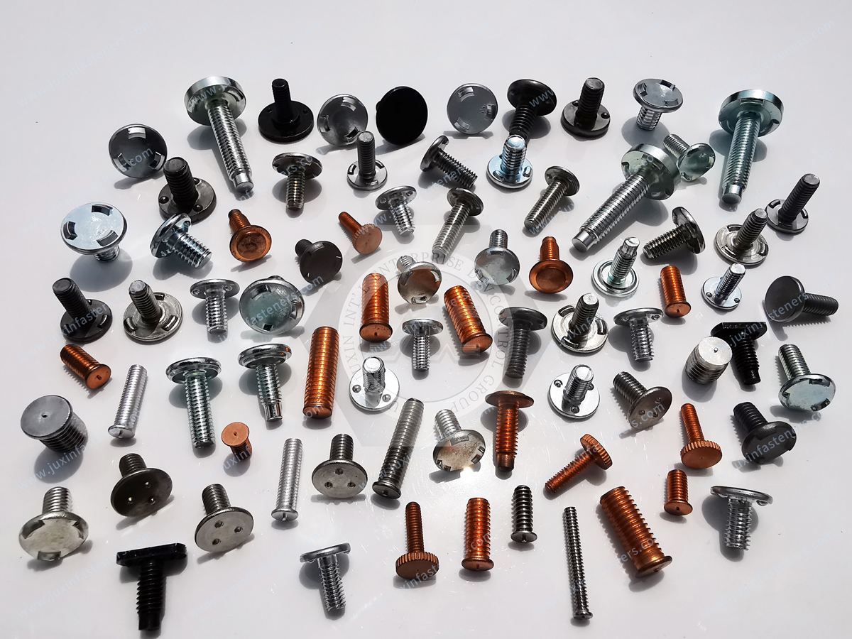
JUXIN FASTENERS supplies industrial weld studs and related fastening products for fabricated metal components and OEM equipment manufacturing.
Our relevant product portfolio includes:
Threaded projection weld studs.
Three-projection weld studs.
Flanged capacitor discharge weld studs.
Non-flanged CD weld studs.
Stainless steel CD weld stud options.
Suitable carbon steel and aluminum configurations.
Metric and Unified inch thread specifications.
Customer-defined stud dimensions and geometries.
Drawing-based OEM fastener evaluation.
Related JUXIN product and engineering pages:
Type UC3 Carbon Steel Projection Weld Studs
Flanged CD Weld Studs – Inch and Metric
Non-Flanged CD Weld Studs – Inch and Metric
Stainless Steel Flanged CD Weld Studs
Projection Weld Studs Engineering and OEM Sourcing Guide
For power generation and energy equipment projects, JUXIN FASTENERS can review customer drawings, material specifications, welding requirements, and purchasing quantities to evaluate suitable product options.
Structural qualification, pressure-equipment suitability, special testing, and project-specific documentation must be confirmed separately where required.
Request a Power and Energy Weld Stud Technical Review or OEM RFQ
Are you sourcing weld studs for electrical cabinets, transformer accessories, power generation equipment, pipe support assemblies, or fabricated energy infrastructure components?
JUXIN FASTENERS welcomes inquiries from equipment manufacturers, engineering teams, fabrication companies, purchasing departments, and international supplier development professionals.
For an accurate technical review and quotation, please provide:
Available 2D drawings or 3D CAD models.
Required stud type and dimensions.
Thread specification.
Stud material and mechanical requirements.
Base material grade and thickness.
Welding process and installation conditions.
Intended application and operating environment.
Required surface finish and corrosion protection.
Inspection, testing, and documentation requirements.
Estimated order quantity and delivery schedule.
If you are evaluating an alternative to an existing weld stud, please include the original drawing and specification.
For structural or pressure-boundary-related applications, provide the governing project requirements and required engineering approvals.
Our objective is to help customers identify technically appropriate welded fastening products that support reliable equipment assembly, efficient manufacturing, and consistent OEM procurement.
JUXIN FASTENERS
Website: https://www.juxinfasteners.com
Email: info@juxinfasteners.com
Send your technical drawings and RFQ to discuss your power generation, energy equipment, or industrial welded stud requirements.
Contact Us
Tel.:
+86 020 8621 0320
+86 020 3121 6067
E-mail:
Technical Support:
Navigation
SEND INQUIREY



