
Call Us
+86 136 6007 9809
Call Us
+86 136 6007 9809

Apr. 21, 2026
High-Performance Thread Insert Nuts for Automotive Plastic Components: Joint Reliability, Engineering Design and OEM Supply
Automotive plastic components increasingly perform functions that were once assigned to metal housings, brackets and equipment supports.
Engineering polymers offer opportunities for weight reduction, integrated component design, electrical insulation and efficient injection molding.
However, fastening a metal screw into a plastic component requires careful consideration of material behavior, load transfer and assembly conditions.
Directly formed plastic threads may be suitable for certain applications, especially where the component is assembled only a limited number of times.
Other applications require a durable metallic internal thread capable of supporting repeated assembly, controlled tightening and service loads.
High-Performance Thread Insert Nuts, also known as Threaded Inserts for Plastics, provide this metallic threaded interface within a properly designed plastic component.
They are used in suitable automotive electronics housings, lighting assemblies, interior components, sensor modules, electrical enclosures and auxiliary mounting systems.
However, a high-performance threaded insert is not defined simply by its material, outside diameter or knurl pattern.
The actual performance depends on the interaction between the insert, plastic resin, boss geometry, installation process, mating screw, applied load and service environment.
For automotive design engineers, the central question is whether the complete joint meets its mechanical and environmental requirements.
For manufacturing engineers and production managers, the challenge is maintaining consistent installation quality while controlling cycle time, scrap, tooling wear and production downtime.
For procurement managers and supplier development teams, the objective is to source dimensionally consistent inserts that meet approved specifications and remain suitable for repeat OEM production.
This guide explains how these requirements are connected and how threaded insert selection can influence the reliability and total installed cost of automotive plastic assemblies.
What Makes a Thread Insert Nut High-Performance?
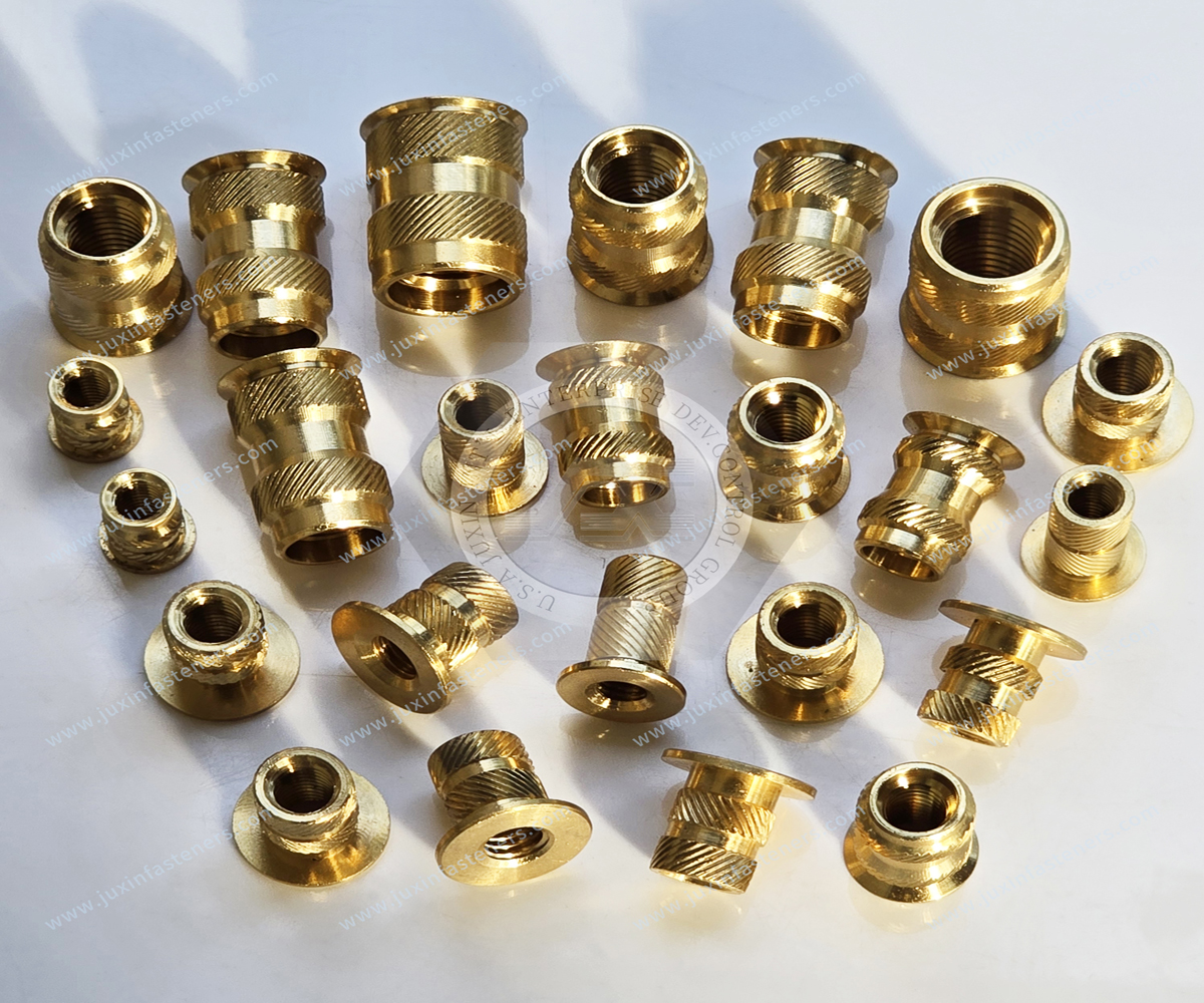
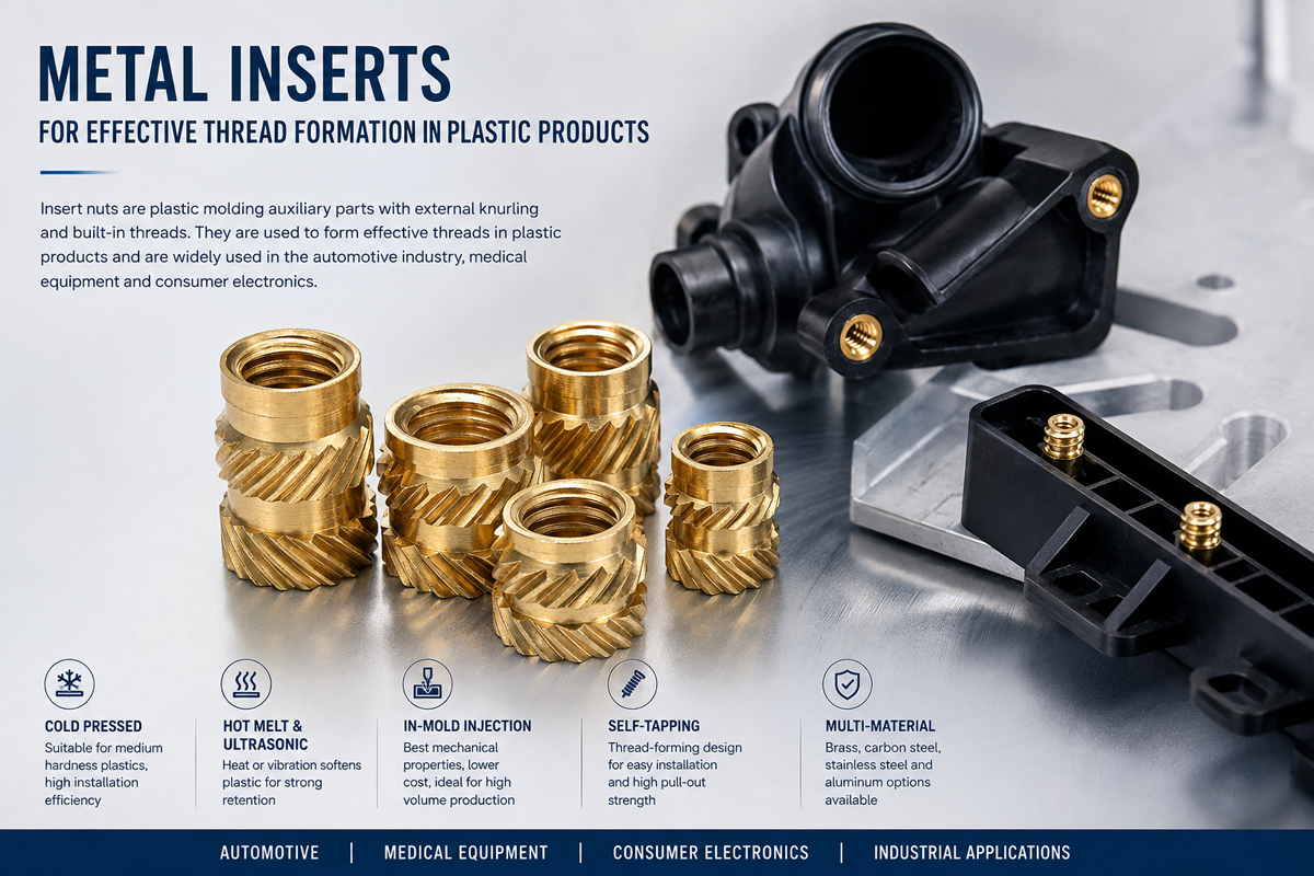
A thread insert nut is a metallic component that provides an internal thread within a plastic part.
The external surface of the insert engages the surrounding polymer through features such as knurls, undercuts, grooves, barbs, flanges or external threads.
The metal insert provides the mating thread, while the plastic component supports and retains the insert.
High-performance characteristics may include:
Suitable axial pull-out resistance
Suitable rotational torque resistance
Durable internal threads
Controlled installation depth
Consistent engagement with the plastic
Compatibility with the selected polymer
Resistance to relevant service conditions
Repeatable performance in production
These characteristics must be evaluated against the actual application requirements.
A threaded insert with excellent torque resistance may still have insufficient axial retention.
An insert with high pull-out strength may still rotate during screw tightening.
Likewise, a strong metallic thread cannot prevent failure if the surrounding plastic boss cracks or creeps under load.
High Performance Is an Assembly-Level Requirement
The correct engineering question is not simply:
"Which insert is strongest?"
It is:
"Which combination of insert geometry, plastic material, installation method and joint design provides the required performance throughout the product's intended service life?"
This distinction is particularly important in automotive applications involving vibration, temperature changes, repeated maintenance or sustained clamping loads.
Thread Insert Nuts Versus Direct Screws into Plastic
Metal threaded inserts are not necessary for every plastic component.
A screw designed to form or engage threads directly in plastic may be suitable where the load, service life and assembly requirements permit.
Thread insert nuts become particularly useful when an application requires:
Repeated assembly and disassembly
Reusable machine-screw threads
Reduced thread wear during maintenance
Controlled engagement with a metallic thread
A serviceable connection
A specific assembly or load-transfer arrangement
When Direct Plastic Threading May Be Preferable
For a low-load component assembled once, direct fastening into plastic may reduce the number of parts and eliminate an insert installation operation.
When a Metal Threaded Insert May Be Preferable
For an enclosure that must be opened repeatedly, a metallic insert may provide a more durable threaded interface.
Total Cost Consideration
The correct comparison includes not only the insert price but also molding complexity, installation labor, assembly cycle time, serviceability and potential failure costs.
Automotive Applications of High-Performance Threaded Inserts
Thread insert nuts can support a range of automotive plastic assemblies.
Their suitability depends on the actual component design and loading requirements.
Automotive Electronic Control Unit Housings
ECU housings may require reusable threaded points for covers, brackets and internal mounting features.
Important considerations include:
Dimensional accuracy
Plastic resin selection
Assembly torque
Environmental exposure
Thermal cycling
Service access
Insert retention
Automotive Sensor Housings
Selected sensor enclosures may use metal threaded inserts for mounting or enclosure assembly.
The design should consider vibration, installation alignment and sealing requirements.
Automotive Lighting Systems
Headlamp housings, LED module supports and selected lighting components may require metallic threaded attachment points.
Temperature exposure and plastic material compatibility are important.
Dashboard and Interior Components
Interior assemblies may require repeated fastening during manufacturing or service.
A suitable insert can provide a reusable threaded interface.
EV and Hybrid Vehicle Electronics
Selected EV electronic enclosures, control modules and auxiliary equipment may use threaded inserts.
However, high-voltage electrical isolation, sealing, thermal safety and crash requirements must be evaluated separately.
A threaded insert does not automatically establish compliance with battery or high-voltage safety requirements.
Auxiliary Brackets and Equipment Supports
Some plastic brackets and housings use threaded inserts to connect metal hardware.
The designer must verify that the surrounding plastic can support the intended load.
Safety-Critical Application Limitations
Conventional inserts embedded in plastic should not automatically be selected for suspension mounting,
crash structures or other primary safety-critical connections.
Those applications require dedicated structural design and validation.
Pull-Out Strength: Understanding Axial Retention
Pull-out resistance is one of the principal performance characteristics of a threaded insert.
It describes the joint's resistance to an axial force attempting to remove the insert from the plastic.
Factors Influencing Pull-Out Resistance
Insert length
Outside diameter
Undercut geometry
Knurl configuration
Plastic material
Boss dimensions
Hole quality
Installation process
Temperature
Test conditions
Why Insert Length Matters
A longer insert may provide additional engagement area with the surrounding plastic.
However, increasing insert length also requires additional boss depth and may increase material and installation costs.
The preferred length should be selected according to the required load and available component geometry.
Why Plastic Material Matters
An insert tested in unfilled ABS may perform differently in PC/ABS, PP, PA66 or glass-filled polyamide.
The same insert may also produce different results when installed into molded versus drilled holes.
Why Published Pull-Out Values Require Caution
Catalog pull-out values are typically obtained under specific test conditions.
They should not be treated as guaranteed performance in another manufacturer's plastic component.
For OEM qualification, pull-out testing should use the actual resin, boss geometry and installation process.
Torque-Out Resistance: Preventing Insert Rotation
Torque-out resistance describes the insert's ability to resist rotation relative to the surrounding plastic.
This characteristic is important when a mating screw is tightened or removed.
Common Causes of Insert Rotation
Insufficient engagement of external knurls
Incorrect hole diameter
Inadequate plastic flow
Incorrect installation temperature
Poor boss geometry
Excessive assembly torque
Incompatible insert design
Why Knurl Geometry Matters
External knurls help create mechanical engagement with the host plastic.
Different knurl patterns may be used to resist rotation.
However, aggressive knurling is not always better.
A profile that displaces too much material may increase boss stress or contribute to cracking.
Opposing Knurl Patterns
Some inserts use opposing diagonal or helical knurls to improve resistance to rotational movement.
The actual performance depends on the geometry and installation conditions.
Engineering Selection Principle
Evaluate torque-out resistance independently from pull-out resistance.
A strong axial connection does not automatically provide sufficient rotational retention.
The Role of Undercuts and External Grooves
Undercuts and grooves provide locations where plastic can engage the insert.
For heat-set and ultrasonic installation, softened thermoplastic must flow into these features before cooling.
Insufficient Plastic Flow
If the plastic does not adequately fill the retention features, the installed insert may have reduced mechanical retention.
Excessive Material Displacement
If the insert displaces too much plastic, the surrounding boss may deform or crack.
Correct Design Balance
The insert geometry and prepared hole should allow sufficient material engagement without imposing unacceptable stress on the plastic component.
Why Cross-Section Examination Is Valuable
During process development, a cross-section of an installed insert can help engineers evaluate whether the plastic has properly engaged the external features.
This can be particularly useful when the insert appears correctly installed but produces inconsistent mechanical test results.
Plastic Boss Design for High-Performance Inserts
The plastic boss is the local structure that retains the insert.
A poorly designed boss can limit the performance of even a well-manufactured insert.
Hole Diameter
The hole diameter must match the selected insert and installation process.
An oversized hole may reduce retention.
An undersized hole may increase installation force, create plastic flash or cause cracking.
Hole Depth
The hole must provide sufficient space for the insert and any displaced material.
The mating screw must not bottom out and generate forces that damage or extract the insert.
Boss Outside Diameter
The boss requires sufficient surrounding material to resist installation stress and service loads.
Boss Height
Boss height should accommodate the insert while meeting the component's structural and dimensional requirements.
Ribs and Reinforcement
Properly designed ribs may help support a boss.
However, excessive rib thickness or unsuitable geometry may introduce molding problems.
Molded Knit Lines
A weak knit line near an insert boss can reduce the strength of the surrounding plastic.
The molding process and gate location may therefore affect insert retention.
Boss Design Reference from Industry Practice
SPIROL's published design guidance for certain heat-set and ultrasonic inserts recommends a hole depth at least equal to the insert length plus two thread pitches.
The same guidance discusses a boss outside diameter approximately two to three times the insert diameter as an initial design reference.
These values are not universal requirements.
They must be checked against the selected insert series, resin and actual application.
Why Universal Wall Thickness Values Are Misleading
A fixed minimum wall thickness cannot be applied reliably to every insert.
The necessary wall thickness depends on:
Insert outside diameter
Knurl geometry
Plastic resin
Filler content
Installation method
Applied loading
Molded component geometry
The final design should be verified through suitable testing.
Plastic Hole Geometry: Straight Versus Tapered
Threaded inserts may be designed for straight or tapered holes.
Straight-Hole Inserts
These inserts are intended for hole geometries compatible with their external design.
Tapered Inserts
Tapered inserts may help guide installation and establish the intended contact conditions.
Why the Correct Combination Matters
A tapered insert should not automatically be installed into a straight hole, or vice versa.
The insert supplier's specified hole geometry must be followed.
Molded Holes Versus Drilled Holes
Molded holes may provide favorable surface and dimensional characteristics.
Drilled holes can be suitable in selected applications, but their surface quality and dimensional consistency require evaluation.
Glass-Filled Plastics: Why PA66-GF30 Requires Special Attention
Glass-fiber-reinforced polyamide is used in automotive components where stiffness and dimensional performance are important.
However, reinforcement changes the material's behavior during insert installation.
Glass Fiber Content
Fibers influence local plastic flow and mechanical properties.
Installation Behavior
The material may require different hole dimensions and process settings from an unfilled resin.
Boss Cracking Risk
Insufficient wall thickness or excessive interference may contribute to cracking.
Moisture Conditioning
Polyamide absorbs moisture, which can affect dimensions and mechanical properties.
Fiber Orientation
Injection molding can create local fiber orientation that influences mechanical behavior.
Practical Engineering Recommendation
A heat-set insert qualified in unfilled PA66 should not automatically be approved for PA66-GF30.
The actual resin grade, filler percentage, molding conditions and installation process must be evaluated.
Industry Reference for Filled Materials
SPIROL provides specific hole-size adjustment guidance for some heat-set and ultrasonic insert designs based on glass or mineral filler content.
Those adjustments are tied to the manufacturer's insert geometry and should not be copied indiscriminately to other products.
PC, ABS, PC/ABS and Polypropylene Applications
Different thermoplastics respond differently to heat, pressure and long-term loading.
ABS
Often used in plastic housings and interior components.
Installation settings should reflect the actual resin grade and boss design.
Polycarbonate
May offer useful impact performance but can be sensitive to certain environmental and residual stress conditions.
PC/ABS
Used in various automotive and electronic housings.
The selected insert and installation process must be validated for the actual blend.
Polypropylene
Its stiffness, thermal properties and creep behavior differ from engineering polymers such as PA66.
Retention and long-term loading should be evaluated accordingly.
Why Generic Resin Names Are Insufficient
Two resins with the same broad polymer designation may differ in additives, reinforcement, viscosity and thermal behavior.
For demanding OEM applications, the exact resin grade is important.
Heat-Set Thread Insert Nuts
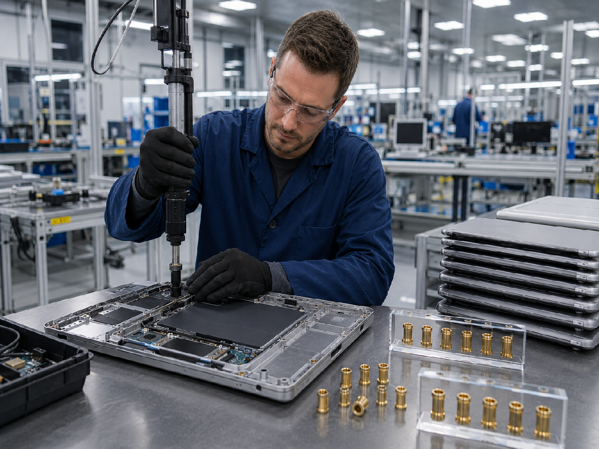
Heat-set installation uses controlled heat to soften thermoplastic around the insert.
The insert is pressed into the prepared hole, allowing the softened polymer to flow into the external retention features.
After cooling, the plastic forms a mechanical interlock.
Critical Process Variables
Insert temperature
Heating method
Insertion speed
Insertion force
Hole diameter
Insertion depth
Tool alignment
Holding and cooling conditions
Potential Advantages
Controlled post-mold installation
Durable metallic threads
Compatibility with selected automated equipment
Good retention when plastic flow is properly developed
Potential Failure Modes
Insufficient plastic flow
Excessive boss deformation
Insert misalignment
Incorrect installation depth
Plastic flash
Inconsistent retention
Why Temperature Alone Is Not Enough
An installation process may fail even when the heating temperature appears correct.
Poor alignment, unsuitable hole geometry or excessive insertion speed can still produce unacceptable results.
Ultrasonic Threaded Inserts
Ultrasonic insertion uses mechanical vibration to generate localized heating at the metal-plastic interface.
The plastic softens and engages the insert's external retention features.
Potential Advantages
Short installation cycles in suitable applications
Localized heating
Integration with automated equipment
Controlled installation when correctly developed
Engineering Considerations
Ultrasonic frequency and amplitude
Applied force
Insertion travel
Horn and tooling design
Part support
Resin response
Insert geometry
Heat-Set Versus Ultrasonic Installation
Neither process is universally superior.
The selection should be based on the plastic material, part geometry, installation equipment, production volume and required performance.
Molded-In Thread Insert Nuts
Molded-in inserts are positioned inside the mold before plastic injection.
The plastic flows around the insert's external features and retains it after cooling.
Potential Advantages
Integrated insert placement during molding
No separate post-mold installation operation
Compatibility with selected thermoplastic and thermoset materials
Manufacturing Challenges
Insert loading into the mold
Positioning accuracy
Mold protection
Plastic flow
Thread contamination
Cycle time
Tooling complexity
Why Molded-In Does Not Automatically Mean Strongest
Molded-in inserts can provide excellent performance in suitable designs.
However, retention depends on geometry, plastic material, molding quality and load direction.
A properly installed heat-set insert may be preferable for some applications.
Press-In and Self-Tapping Alternatives
Not every application requires thermal or ultrasonic installation.
Press-In Inserts
Use mechanical interference or retention features.
They may be suitable for selected plastics and load requirements.
Self-Tapping Inserts
Use external threads or cutting features to engage the plastic.
They may be appropriate where the plastic material and boss geometry support the installation method.
Thermoset Plastics
Cured thermosets generally cannot be remelted.
Molded-in, press-in or suitable self-tapping inserts may be more appropriate than conventional heat-set or ultrasonic installation.
Selection Principle
The best insert is the one that meets the required performance with acceptable manufacturing cost and process risk.
Brass Thread Insert Nuts: Why Material Grade Matters
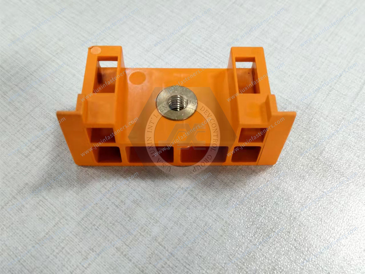
Brass is commonly used for threaded inserts because of its machinability, thermal conductivity and suitability for many installation processes.
Brass Advantages
Good machinability
Useful thermal conductivity
Durable metallic internal threads
Corrosion resistance in many environments
Compatibility with selected heat-insertion methods
Brass Alloy Selection
Different brass alloys have different mechanical properties, machinability and chemical compositions.
The approved drawing should identify the required material grade.
Lead Content
Some free-machining brass alloys contain lead.
Lead content may be relevant to automotive material restrictions and environmental requirements.
Important Compliance Principle
A brass insert should not be described as lead-free, RoHS-compliant or compliant with
a particular automotive material requirement unless the actual alloy and supporting documentation establish that status.
Lead-Free Alternatives
Lead-free brass or alternative metal materials may be evaluated when required.
The selected material must still meet the mechanical, dimensional and installation requirements.
Stainless Steel Threaded Inserts
Stainless steel may be considered where corrosion resistance or specific mechanical requirements justify its use.
However, its thermal properties and installation behavior differ from brass.
Carbon Steel Threaded Inserts
Carbon steel may be suitable for selected designs.
Corrosion protection and installation compatibility must be considered.
Aluminum Threaded Inserts
Aluminum may be considered where weight is important and the required mechanical performance can be achieved.
The final choice should account for thread strength, corrosion behavior and manufacturing cost.
Material Selection Should Follow the Application
A stronger metal does not automatically create a stronger plastic joint.
The surrounding polymer may remain the limiting component.
Thread Insert Nuts and Screw Tightening Torque
The mating screw applies load to the insert and surrounding plastic.
Excessive tightening torque can cause:
Insert rotation
Boss cracking
Plastic deformation
Thread damage
Loss of retention
Why Metal Fastener Torque Tables Are Not Enough
Conventional torque values for metal-to-metal joints should not automatically be used for inserts installed in plastic.
The allowable assembly torque depends on the complete joint.
Required Engineering Evaluation
Screw size
Thread pitch
Screw material
Insert material
Insert engagement length
Plastic resin
Boss geometry
Clamped component
Service loading
Screw Length and Jack-Out Prevention
A screw that bottoms out in the hole may generate an axial force that pushes or pulls the insert out of the plastic.
This failure is commonly described as jack-out.
How to Reduce Jack-Out Risk
Provide sufficient hole depth.
Select an appropriate screw length.
Verify the mating component's clearance hole.
Ensure the load is transferred through the intended insert surfaces.
Consider a headed insert when the joint geometry requires additional bearing area.
Mating-Part Clearance Is Critical
A clearance hole that is too large may allow the mating component to load the plastic incorrectly.
The correct hole geometry should be established with the insert and assembly design.
Headed Versus Unheaded Inserts
Headed Inserts
A head can provide additional bearing area and may improve the load path in certain configurations.
Unheaded Inserts
May provide compact geometry and, in selected symmetrical designs, simpler automatic feeding.
Why a Head Is Not Always Better
A headed insert may require additional space and material.
The decision should reflect the required loading, component geometry and production method.
Plastic Creep and Stress Relaxation
Plastics can deform under sustained mechanical loading.
This behavior may be more significant at elevated temperatures.
Creep
Time-dependent deformation under sustained load.
Stress Relaxation
Reduction in stress under an approximately constant deformation condition.
Why This Matters for Bolted Joints
A threaded insert may retain the screw thread while the surrounding plastic gradually loses clamping force.
The metal thread alone cannot eliminate this behavior.
Compression Limiters for Plastic Assemblies
A compression limiter is a separate component designed to carry compressive loading through the joint.
Where appropriate, it can help prevent excessive compression of the plastic and support preload retention.
Threaded Insert Versus Compression Limiter
The threaded insert provides the internal thread.
The compression limiter provides a controlled load path for compressive forces.
They serve different functions and may be used together in suitable assemblies.
Engineering Design Consideration
The compression limiter must be positioned and dimensioned so that the intended load path is established.
A poorly designed limiter may not provide the expected benefit.
Thermal Cycling and Differential Expansion
Automotive assemblies experience changing temperatures during manufacturing, storage and service.
Metals and polymers generally expand and contract at different rates.
Potential Effects
Changes in local stress
Insert retention variation
Boss deformation
Changes in clamp load
Material aging
Why Room-Temperature Testing Is Insufficient
A joint that performs well at room temperature may behave differently after thermal cycling or prolonged heat exposure.
The test plan should reflect the intended service environment.
Moisture and Chemical Exposure
Polyamide and other moisture-sensitive polymers may experience dimensional and mechanical changes.
Automotive components may also encounter oils, cleaning agents, humidity and other chemicals.
Material compatibility should be evaluated according to the actual application.
Vibration and Repeated Assembly
Automotive threaded connections may experience vibration and repeated service operations.
A metal insert can provide a durable thread, but it does not automatically prevent the mating screw from loosening.
Relevant Design Factors
Joint preload
Insert retention
Plastic stiffness
Screw engagement
Vibration direction
Temperature
Locking method
Repeated assembly requirements
Fatigue and Vibration Testing
Where relevant, the joint should be evaluated using suitable cyclic loading or vibration tests.
A static pull-out test does not establish fatigue performance.
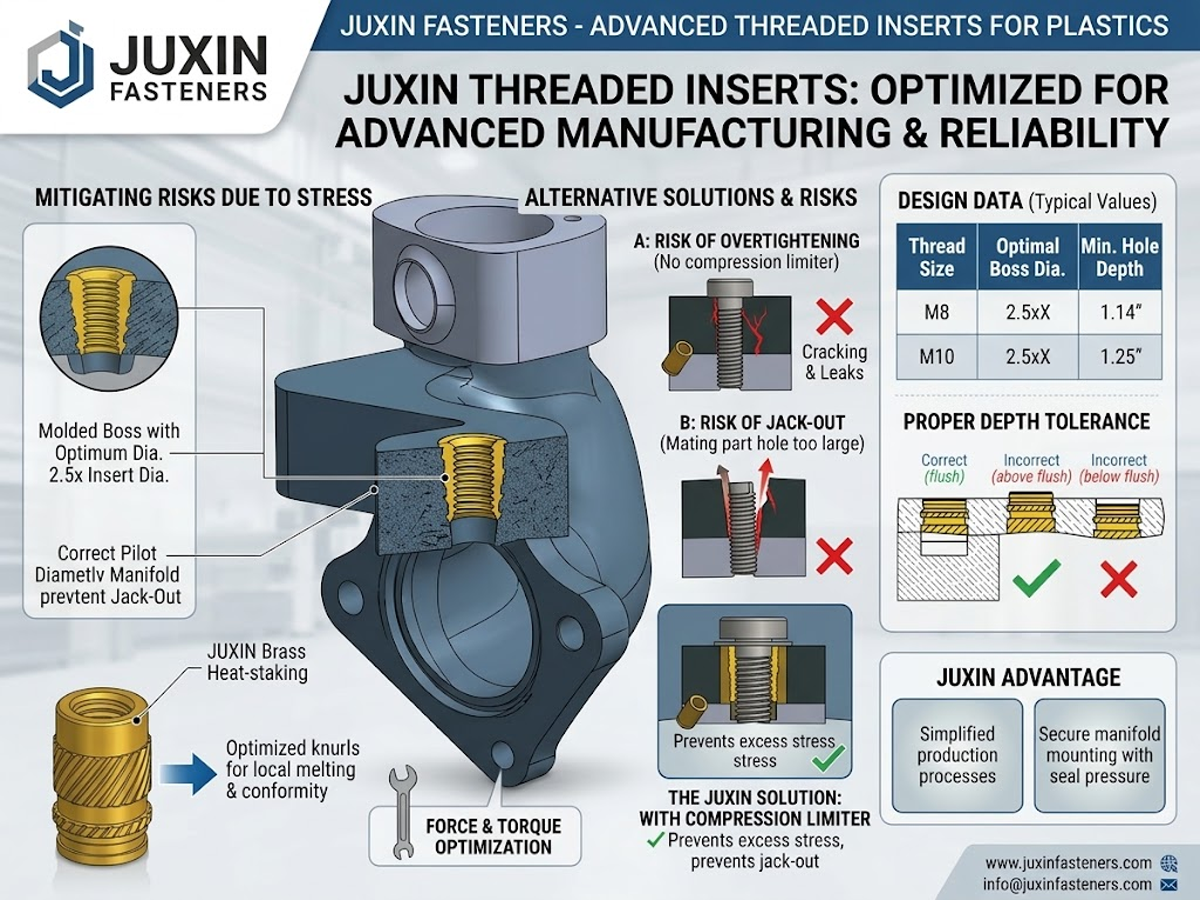
Threaded Insert Failure Analysis
When an insert fails, the location and type of failure provide important diagnostic information.
Insert Rotates in the Plastic
Investigate knurl engagement, hole dimensions, installation conditions and assembly torque.
Insert Pulls Out Axially
Investigate retention geometry, boss design, installation quality and applied axial loading.
Plastic Boss Cracks
Investigate excessive interference, insufficient wall thickness, resin properties and molding quality.
Insert Sits Above the Plastic Surface
Investigate insertion depth, temperature, force and tooling alignment.
Insert Is Installed Too Deep
Investigate travel control and process settings.
Plastic Flash Enters the Thread
Investigate material displacement, insert design and installation conditions.
Thread Strips
Investigate thread engagement, mating screw specification and tightening conditions.
Joint Loses Preload
Investigate plastic creep, relaxation, thermal exposure and the need for a suitable compression limiter.
Intermittent Failures Between Production Lots
Investigate changes in insert geometry, resin grade, molding conditions and installation settings.
How to Separate Insert Quality from Installation Quality
An important OEM supplier-development challenge is determining whether a failure originates from the insert, plastic component or installation process.
Potential Insert-Related Issues
Incorrect internal thread
Outside diameter variation
Knurl geometry inconsistency
Material mismatch
Burrs
Incorrect length
Surface-condition variation
Potential Plastic Component Issues
Hole diameter variation
Insufficient boss material
Weak molding knit lines
Resin degradation
Filler-content variation
Inconsistent moisture conditioning
Potential Installation Issues
Incorrect temperature
Incorrect ultrasonic parameters
Poor alignment
Excessive insertion force
Incorrect installation depth
Inadequate cooling
Tooling wear
Potential Assembly Issues
Excessive tightening torque
Incorrect screw length
Incorrect clearance hole
Poor component alignment
Inadequate load path
Recommended Investigation Method
Compare accepted and failed components.
Measure critical insert and plastic dimensions.
Review the actual resin grade.
Check installation equipment and settings.
Evaluate failure modes through appropriate tests.
Document the corrective action and confirm its effectiveness.
Automated Threaded Insert Installation
Automated installation can support repeatable production when the insert geometry and equipment are compatible.
Heat Installation Automation
Equipment may control heating, insertion travel, speed, force and holding conditions.
Ultrasonic Installation Automation
Equipment may monitor ultrasonic settings, force and travel.
Automatic Feeding
Insert geometry influences orientation and feeding reliability.
Vision and Position Inspection
Depending on the system, inspection may verify insert presence, orientation or installation depth.
Why Automation Does Not Guarantee Quality
A successful machine cycle does not prove that the insert has achieved the required pull-out or torque-out resistance.
The process must be correlated with actual mechanical testing.
Production Manager Performance Indicators
Installation cycle time
First-pass acceptance
Feeding reliability
Equipment uptime
Tooling wear
Scrap rate
Rework
Changeover time
Inspection effort
Cost per accepted assembly
Why the Lowest Cycle Time Is Not Always the Best
An aggressive insertion process may shorten cycle time but increase plastic damage or retention variation.
Production optimization should consider both throughput and accepted assembly quality.
Pre-Production Process Validation
Before starting repeat production, the OEM should establish a validated installation process.
Representative Samples
Use the actual plastic resin and production-representative molded components.
Critical Parameters
Identify the installation variables that influence retention and component quality.
Mechanical Testing
Evaluate pull-out and torque-out performance.
Dimensional Inspection
Verify installation depth, alignment and relevant boss dimensions.
Environmental Evaluation
Where required, assess thermal cycling, moisture conditioning, vibration and aging.
Change Control
Identify changes that require additional validation.
These may include a different resin, insert material, knurl design, installation machine or molding process.
Quality Control for Automotive Threaded Inserts
Quality control should cover the complete assembly process.
Incoming Insert Inspection
Depending on the approved specification:
Internal thread dimensions
Overall length
Outside diameter
Knurl geometry
Undercuts
Head dimensions
Material identification
Surface condition
Visual defects
Plastic Component Inspection
Verify the relevant hole and boss dimensions.
Installation Process Monitoring
Record critical parameters where the equipment and quality plan require it.
Post-Installation Inspection
Check insert position, depth and visible damage.
Mechanical Testing
Use suitable pull-out, torque-out and other tests according to the customer specification.
Environmental Testing
Evaluate service-related conditions where required.
Traceability
Maintain the agreed level of lot and process identification.
Inspection Frequency
Inspection frequency should follow the approved control plan and application risk.
A general claim of 100% inspection should not replace defined methods and acceptance criteria.
Relevant International Standards
Thread insert nuts for plastics are commonly specified using product drawings, thread standards, material specifications and customer-specific requirements.
There is no single universal ISO or DIN standard that defines every heat-set, ultrasonic, molded-in and press-in insert geometry.
ISO 261
Defines general-purpose metric screw thread series.
ISO 965 Series
Addresses metric screw thread tolerances.
ASME B1.1
Covers Unified inch screw threads, including UNC and UNF.
ASTM B16/B16M
May be relevant to certain free-cutting brass material specifications where the selected alloy and product form are within its scope.
EN 12164
May be relevant to copper and copper alloy rod for free machining where applicable.
Customer Material Requirements
Automotive OEMs may specify additional restrictions for chemical composition, lead content, corrosion resistance and documentation.
The actual requirements must be confirmed for each project.
Metric and Inch Threaded Inserts
Common metric designations include:
M2 × 0.4
M2.5 × 0.45
M3 × 0.5
M4 × 0.7
M5 × 0.8
M6 × 1.0
M8 × 1.25
Common Unified inch designations include:
2-56 UNC
4-40 UNC
6-32 UNC
8-32 UNC
10-24 UNC
10-32 UNF
1/4-20 UNC
These are examples of thread designations, not confirmation of availability for every insert design.
Metric, UNC, UNF, BSW and BSF are different thread systems.
They should not be treated as directly interchangeable.
Why Insert Cross-Referencing Requires More Than Matching Threads
Two inserts may have the same M4 internal thread but different:
Outside diameters
Lengths
Knurl patterns
Undercuts
Hole requirements
Installation methods
Materials
Surface treatments
Pull-out performance
Torque-out performance
A purchasing cross-reference should therefore be treated as a candidate replacement, not an automatically approved equivalent.
Recommended OEM Second-Source Qualification
Confirm the existing part drawing.
Identify critical characteristics.
Compare the proposed replacement geometry.
Review material and coating requirements.
Install samples using the actual production process.
Evaluate mechanical and environmental performance.
Approve the replacement through the customer's change-control process.
Total Installed Cost and Supplier Development
A low insert price does not necessarily produce the lowest assembly cost.
Additional costs may include:
Mold tooling
Installation equipment
Cycle time
Feeding problems
Inspection
Scrap
Rework
Maintenance
Assembly failures
Supplier changes
Short Versus Long Inserts
A shorter insert may reduce material use and installation time where performance requirements permit.
A longer insert may provide additional retention potential but requires more space and material.
Headed Versus Unheaded Inserts
A headed insert may improve load transfer in certain configurations.
An unheaded symmetrical insert may simplify orientation in some feeding systems.
Heat-Set Versus Molded-In Cost
Molded-in inserts remove a separate insertion operation but may increase molding complexity.
Post-mold installation adds a process step but can simplify tooling and reduce certain mold-related risks.
Procurement Decision
Compare total installed cost, quality risk, supplier capability and production flexibility rather than unit price alone.
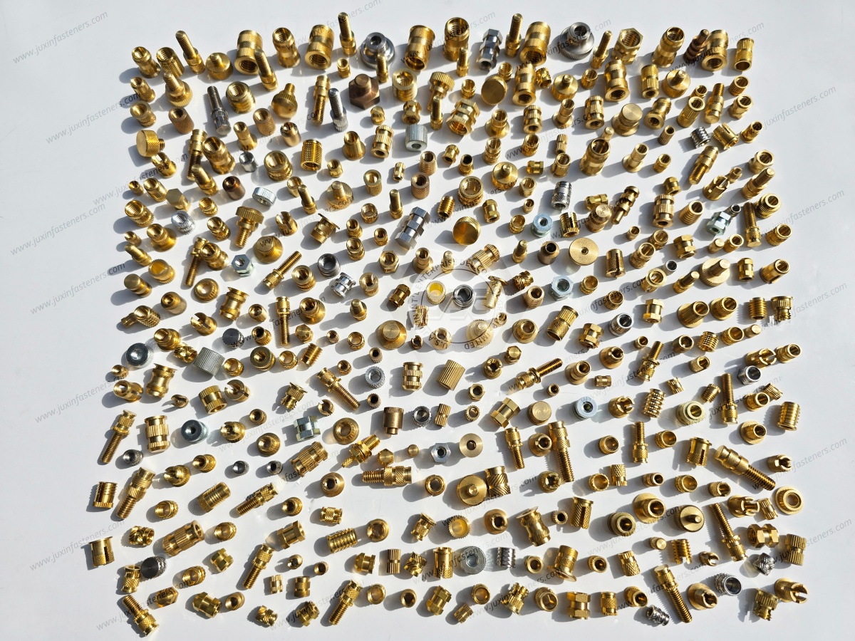
JUXIN FASTENERS High-Performance Thread Insert Nut Solutions
JUXIN FASTENERS supplies industrial threaded inserts and related fastening components for plastic assemblies.
Relevant product families include:
Brass Heat-Set Thread Insert Nuts
Ultrasonic Threaded Inserts
Molded-In Threaded Inserts
Tapered Threaded Inserts
Headed and Unheaded Threaded Inserts
Stainless Steel Threaded Inserts
Steel Threaded Inserts
Custom Threaded Inserts
Drawing-Based OEM Threaded Bushings
Specific materials, dimensions, thread sizes, finishes, inspection arrangements and commercial terms require project-level confirmation.
Related JUXIN FASTENERS Products and Engineering Resources
Custom Threaded Inserts for OEM Plastic Components
M6 Brass Tapered Heat-Set Inserts for Plastic
M8 Brass Tapered Heat-Set Inserts for Plastic
Thread Inserts for Ultrasonic Installation — JX-HTD / JX-FHTD
Threaded Inserts for Plastic — Engineering Guide
These product pages provide starting points for technical evaluation.
Final product selection should follow the approved drawing, plastic material and installation requirements.
Frequently Asked Questions
What are high-performance thread insert nuts?
They are metallic threaded inserts selected and validated to meet defined retention,
thread durability, assembly and service requirements in plastic components.
Are high-performance threaded inserts always made from brass?
No. Brass is common, but stainless steel, carbon steel and aluminum may be appropriate depending on the application.
What determines pull-out strength?
Insert geometry, plastic material, boss design, installation quality and testing conditions all influence pull-out resistance.
What determines torque-out resistance?
External retention features, plastic engagement, hole geometry and installation quality are important factors.
Does a longer insert always perform better?
Not necessarily. Longer inserts may provide additional engagement but also require more space and material.
Can threaded inserts prevent plastic creep?
No. The metal thread does not eliminate creep or stress relaxation in the surrounding polymer.
When should a compression limiter be considered?
When the joint requires controlled compressive loading and sustained preload in a plastic assembly.
Can threaded inserts be used in PA66-GF30?
Suitable designs may be used, but the actual glass-filled resin and installation process must be validated.
Are heat-set inserts suitable for thermoset plastics?
Conventional heat-set installation depends on softening thermoplastic and is generally unsuitable for cured thermosets.
Are molded-in inserts always stronger than heat-set inserts?
No. The result depends on the complete assembly and manufacturing process.
What causes a threaded insert to spin?
Possible causes include poor knurl engagement, incorrect hole dimensions, installation defects or excessive tightening torque.
What causes a threaded insert to pull out?
Possible causes include insufficient retention, inadequate boss geometry, unsuitable installation or excessive axial loading.
Can an insert pass a pull-out test but fail during tightening?
Yes. Pull-out and torque-out resistance are different characteristics.
Can threaded inserts be used in EV electronics?
They may be suitable for selected housings and auxiliary assemblies, subject to the relevant mechanical, electrical and environmental requirements.
Are metric and UNC inserts interchangeable?
No. The thread systems differ.
Can a competitor's insert be replaced with a JUXIN insert?
A proposed replacement can be evaluated using drawings, critical dimensions, material requirements and testing in the actual application.
What should an OEM provide for a custom insert quotation?
The drawing, plastic material, installation method, boss dimensions, mechanical requirements and estimated order volume are important starting points.
OEM RFQ — High-Performance Thread Insert Nuts for Automotive Plastics
JUXIN FASTENERS welcomes inquiries from automotive OEMs, Tier-1 and Tier-2 suppliers, plastic injection molding companies,
automotive electronics manufacturers, design engineers, manufacturing engineers, production managers and international procurement teams.
For accurate technical evaluation and quotation, please provide the following information where available.
Insert Drawing and Specifications
2D engineering drawing
3D CAD model where available
Internal thread designation
Metric or Unified inch thread system
Outside diameter
Overall length
Knurl and undercut geometry
Headed or unheaded configuration
Material grade
Surface treatment
Critical dimensional tolerances
Plastic Component Information
Plastic resin grade
Glass-fiber or mineral filler percentage
Molded hole diameter
Hole tolerance
Hole depth
Boss diameter
Boss wall thickness
Relevant molding conditions
Installation Requirements
Heat-set, ultrasonic, molded-in or mechanical installation
Installation equipment
Required installation depth
Automatic feeding requirements
Production cycle considerations
Mechanical and Environmental Requirements
Pull-out resistance
Torque-out resistance
Assembly tightening torque
Repeated assembly requirements
Thermal cycling
Vibration
Moisture exposure
Chemical exposure
Required inspection and testing criteria
Commercial Requirements
Prototype quantity
Sample requirements
Estimated annual demand
Minimum order quantity expectations
Packaging requirements
Delivery schedule
Required documentation
Company: Juxin Fasteners
Website: https://www.juxinfasteners.com/
Email: info@juxinfasteners.com
Contact JUXIN FASTENERS with your engineering drawings and application requirements to discuss high-performance thread insert nuts,
brass heat-set inserts, ultrasonic threaded inserts and drawing-based OEM threaded fastening solutions.
Reliable automotive plastic fastening requires the correct insert geometry, compatible polymer,
validated installation process, controlled assembly loading and consistent product specifications.
Contact Us
Tel.:
+86 020 8621 0320
+86 020 3121 6067
E-mail:
Technical Support:
Navigation
SEND INQUIREY



